

Research progress on electrical property and electromechanical coupling behaviors of carbon fiber composites
-
摘要: 碳纤维复合材料具有良好的导电性能,但其作为增强体的树脂基复合材料的导电性能与增强体结构显著相关,且在加载条件下的结构变形触发碳纤维复合材料的导电行为发生改变,这一特性在智能传感器方面具有重要的应用。本文从复合材料电阻法结构健康监测应用出发,着重概述了不同维度增强体碳纤维树脂基复合材料的导电性能和预测模型、表面电势场分布和主要测量技术及力电耦合行为和本构模型,以期为碳纤维复合材料“材料-结构-功能”一体化集成系统的设计提供新方向和新途径。Abstract: Carbon fiber composites have good electrical conductivity, however, the electrical conductivity of the resin matrix composites is significantly related to reinforcement architectures. The structural deformation under external load triggers the modification in the conductive behavior of carbon fiber composites, which has an important application in smart sensors. Based on the utilization of electrical resistance method in structural health monitoring for composites, this paper focuses on the overview of electrical conductivity and predictive models, surface potential field distribution and main measurement technologies, as well as electromechanical coupling behavior and constitutive models of carbon fiber reinforced resin matrix composites with different dimensional architectures. It is expected to provide a new direction and path to design "material-structure-performance" integrated system in carbon fiber composites.
-
碳纤维及其复合材料作为国家战略新兴材料,因其轻质高强、高冲击损伤容限和多重增强结构混杂制造等特性,广泛应用在航空航天、远洋船舶、轨道交通和新能源汽车等高精尖技术领域[1-2]。在实际工程应用中,碳纤维复合材料构件易遭受各种异物撞击和循环加载等多重外部威胁,线弹性的力学行为和脆性断裂的失效特性极易引发灾难性崩塌事故[3-5],造成重大经济损失和人员伤亡,因此及时跟踪和监测复合材料的损伤起始和扩展对优化材料使用寿命和性能至关重要。结构健康监测(Structural health monitoring,SHM)是利用集成在工程结构中的传感器网络,实时提取结构损伤特征参数和损伤敏感指标来识别结构健康状态,从而建立一种状态监测、特征识别和损伤评估的系统,实现在役工程结构的健康监测诊断[6]。SHM能够准确预测变形和损伤位置,保证结构的完整性和运行安全性,为工程结构的管理和养护提供决策支撑。碳纤维复合材料除优异的损伤容限和热传导性能以外,突出的电导特性和压阻效应等多功能属性近年来逐步受到重视[7]。
1. 碳纤维复合材料的多功能属性
碳纤维复合材料在外部承载下结构变形诱发电阻发生相应变化,本身可作为智能传感器件记录损伤演变过程,在实现结构材料承载的同时发挥功能材料自我感应的作用,在SHM应用中具有巨大的潜在价值[8-10],如图1所示。利用电阻变化及时跟踪监测复合材料损伤起始和扩展,提前做出危险预警和应急防范,对研究复合材料失效机制、降低安全事故和优化材料使用寿命至关重要[11-13]。相较于超声波检测技术、光纤检测技术、声发射技术、热成像技术和兰姆波检测技术等传统嵌入式高成本结构健康监测技术,电阻法利用碳纤维树脂基复合材料自身的压阻效应实现自我智能监测,无需依赖复杂的监测仪器和数据处理系统便可实现材料自身健康状态的原位监测,从而为复合材料损伤起始和积累过程提供精确实时的电信号信息[14]。
![]() 图 1 碳纤维复合材料在结构健康监测(SHM)中的应用:(a) 力电耦合行为;(b) 导电机制;(c) 飞机机翼监测;(d) 桥梁承载监测Figure 1. Application of carbon fiber composites in structural health monitoring (SHM): (a) Electromechanical coupling behavior; (b) Conductive mechanism; (c) Aircraft wing monitoring; (d) Bridge bearing monitoringΔR—Relative resistance change; R0—Initial resistance; σ1—Stress; ε1—Strain
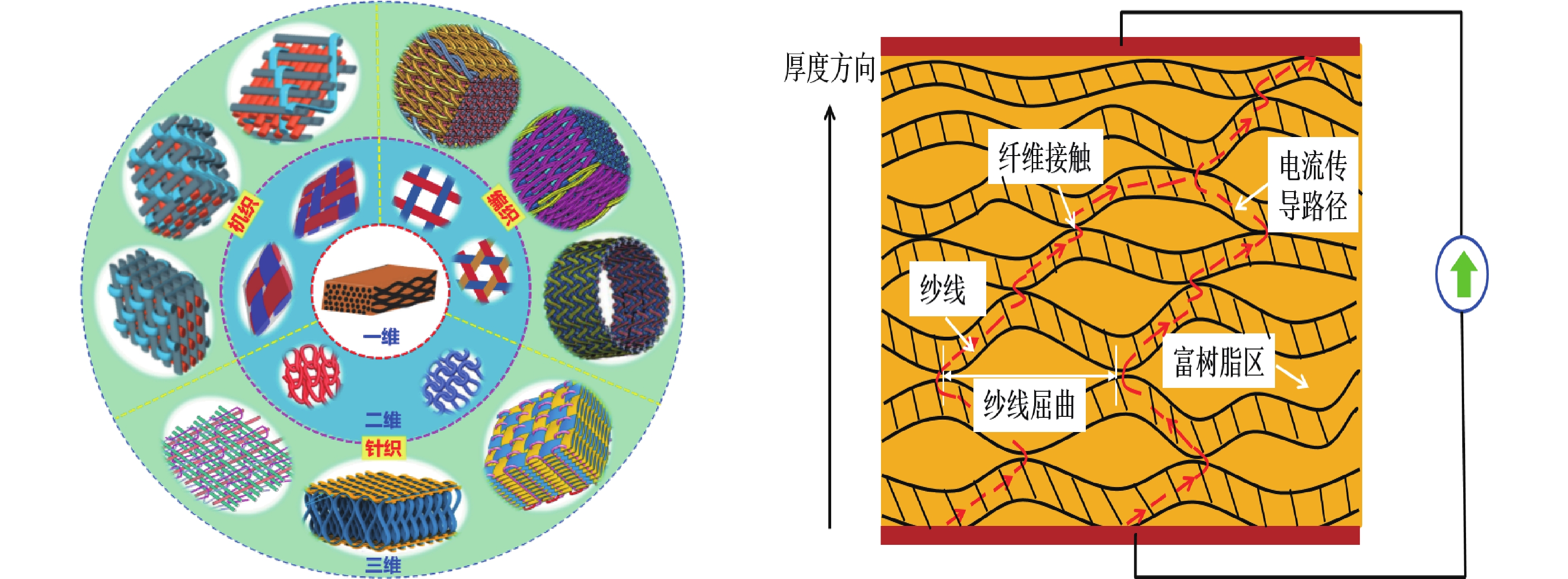
图 1 碳纤维复合材料在结构健康监测(SHM)中的应用:(a) 力电耦合行为;(b) 导电机制;(c) 飞机机翼监测;(d) 桥梁承载监测Figure 1. Application of carbon fiber composites in structural health monitoring (SHM): (a) Electromechanical coupling behavior; (b) Conductive mechanism; (c) Aircraft wing monitoring; (d) Bridge bearing monitoringΔR—Relative resistance change; R0—Initial resistance; σ1—Stress; ε1—Strain碳纤维复合材料的电导特性在纵向、横向和厚度方向均不同,呈明显的电各向异性。碳纤维的电导率约为0.58~1.15×10⁵ S/m,远高于近似绝缘材料的高聚物树脂基体,因此复合材料中碳纤维增强体的结构决定其最终的电导性能[15]。随着纺织织造技术的不断革新和日益成熟,增强体的结构历经一维线性结构(单/多向纤维材料)、二维平面结构(机织、编织、针织和非织造)和三维立体结构(三维机织、编织和针织)的发展变化[16],如图2所示。
![]() 图 2 复合材料不同维度增强体结构Figure 2. Different dimensional reinforcement structure of composites
图 2 复合材料不同维度增强体结构Figure 2. Different dimensional reinforcement structure of composites在复合材料增强体结构中,碳纤维纱线无序接触[17]、穿插交织[18]和屈曲变形[19],导致内部的电流传导路径随机分布,在复合材料中形成复杂的导电路径(图3),从而对复合材料的电导性能产生重要影响;同时碳纤维复合材料的非均质特性,造成内部导电机制尚不清楚[20]。因此研究和分析碳纤维树脂基复合材料不同维度增强体的电导特性与结构效应,揭示碳纤维复合材料的导电机制和力电耦合行为,对实现碳纤维复合材料在结构健康监测中的导电结构优化和高效配置,拓展碳纤维复合材料的多功能用途,具有重要的经济效益和应用价值。
![]() 图 3 复合材料内部电流传导路径示意图Figure 3. Schematic diagram of internal current conduction path of composites
图 3 复合材料内部电流传导路径示意图Figure 3. Schematic diagram of internal current conduction path of composites2. 碳纤维复合材料电导率研究进展
电导率是衡量复合材料传输电流能力强弱重要的物理指标。当电压施加在导电材料的两端时,电子会朝某一方向流动,从而产生电流。电导率测试方法包括两探针法、四探针法和六探针法。其中四探针法能够有效消除接触电阻对测试结果的干扰,测试结果比两探针法更精确,因此可用于小电阻的测量。实际测量中复合材料的电导率常用体积电导率来表征,定义为电流通过导电材料体内时所表现的电导性能。
2.1 一维增强结构复合材料导电性能
单向(Unidirectional,UD)碳纤维复合材料层压板中纤维沿长度方向取向,导电性能整体上表现为正交各向异性。单向碳纤维复合材料沿主轴纵向、横向与厚度方向的导电特性截然不同:在纵向,电导率受碳纤维连续传导机制的控制,而其他两个方向电导率则受横向或厚度方向上随机分布的纤维接触点的影响。当碳纤维体积含量达到某一个临界值时,整个复合材料内部形成一个三维互联互通的导电网络[21-23] (图4)。Abry等[24]和Todoroki等[25]研究发现复合材料沿主轴3个方向的电导率随着碳纤维体积含量的增加呈上升趋势。在此研究基础上,Wasselynck等[26]和Kane等[27]通过切片取样还原了复合材料内部纤维间相互接触的形貌特征和分布规律,然后采用t分布和正态分布函数建立了三维渗透模型,并通过均质化方法推导出了单向碳纤维复合材料层压板的电导率张量,结果发现当纤维体积含量低于渗透阈值时电导率数值接近于零,当纤维体积含量高于渗透阈值时电导率呈指数增长。
![]()
对于多向碳纤维复合材料层压板的电导率,Xiao等[28]应用电导率经典层压板理论和静电场理论,推导出了正交各向异性碳纤维复合材料层压板的电导率。在上述研究的基础上,Todoroki等[29]和Yamane等[30]引入贡献函数
F(α) ,推导出了单向复合材料层压板沿不同厚度处的等效电导率,并采用等价电导率的方法分析了不同角度铺层复合材料层压板的电导率。在等价电导率方法中,先将2个或3个不同角度铺层进行耦合变换,然后假设成具有双倍或三倍厚度的正交各向异性层合板,结果发现理论计算的结果与实验的结果吻合较好。Athanasopoulos等[31]采用理论推导和实验测试相结合的方法研究并建立了多向复合材料层压板的等效电导率张量模型,发现复合材料面内电导率与其内部微观结构密切相关,通过增加固化压力可以增加纤维接触点,从而提高电导率。Bensaid等[32]忽略厚度方向的影响,采用三维电各向异性壳单元模型推导出多向复合材料层压板面内方向的电导率。Cheng等[33]通过涡流测试方法发现,不同铺层角度之间的界面处的纤维接触点能够产生电流沿厚度方向传导的导电通路,可以显著提高多向复合材料层压板厚度方向的电导率。预测单/多向复合材料电导率的导电模型主要包括渗透模型、纤维接触模型和纤维倾斜模型,具体推导公式和适用条件如表1所示。表 1 单向复合材料层压板电导率预测模型Table 1. Prediction model for electrical conductivity of unidirectional composite laminatesModel Electrical conductivity prediction model Ref. Longitudinal direction Transverse direction Thickness direction Haider model (Composites containing conductive particles) σxx=σfVf+σm(1−Vf) σyy=σzz = σmσf(1+Vf)+σm(1−Vf)σf(1−Vf)+σm(1+Vf) [34] Penetration model(Unidirectional composite) σzz = σf(Vf−Vc)p [35] Bueche model(Composites containing conductive particles) σxx=(1−Vf)/σf+Vfwg/σm1/σmσf [36] Fiber contact model(Multidirectional composites containing angle layers) σxx=πd2X4σfVpdclcos2θ σyy=πd2X4σfVpdclsin2θ [37] Fiber inclination model(Multidirectional composites containing angle layers) σxx=σfVfcos2θ(1−LtanθW) σyy=σfVfsin2θ(1−LcotθW) [37] Effective medium model(Unidirectional composite) σxx=σm[1+Vf(σf−σm)[(σf−σm)(S11+S33)+2σm]2(σf−σm)2(1−Vf)S11S33+σm(σf−σm)(2−Vf)(S11−S33)] [38] McCullough model(Composites containing conductive particles) σii=Vfσf+Vmσm−λiVfVm(σf−σm)2Vfiσf+Vmiσm
Vfi=(1−λi)Vf+λiVm,Vmi=(1−λi)Vm+λiVf, i=1, 2, 3[39] Notes: σf—Fiber conductivity; σm—Resin conductivity; Vf—Fiber volume fraction; Vc—Critical fiber volume fraction; p—Critical exponent; wg—Conductive particle content; d—Fiber diameter; dc—Fiber contact circle diameter; X—Fiber contact coefficient; l—Fiber length; Vp—Contact fiber volume; L—Sample length; W—Sample width; θ—Fiber inclination angle; S—Shape parameter; x, y, z—Coordinate direction; 1, 2, 3—Principal axis direction; λi—Fiber contact factor; σxx, σyy, σzz—Electrical conductivity in the x, y and z directions; σii—Conductivity component. 2.2 二维增强结构复合材料导电性能
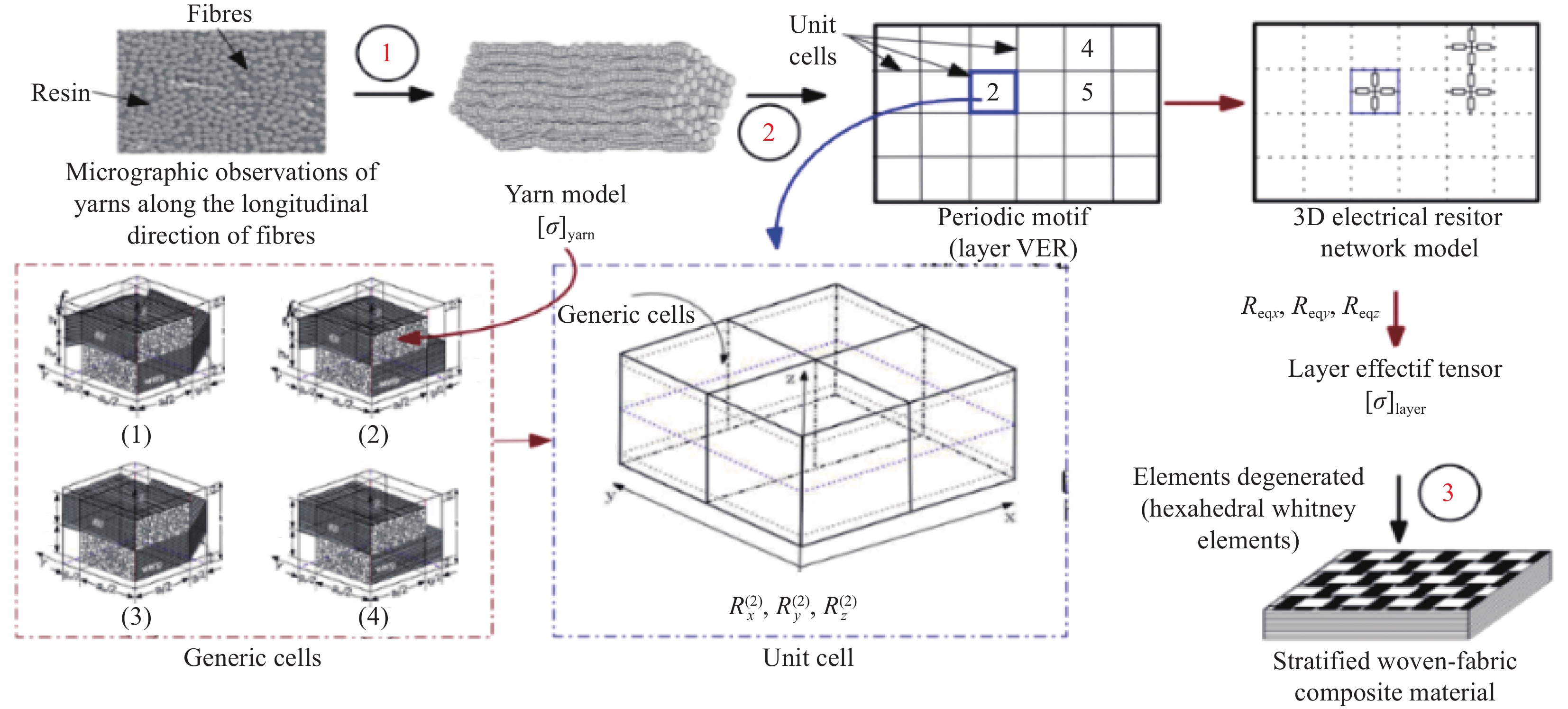
对于二维增强结构碳纤维复合材料,Senghor等[40]通过三步法建立了多尺度均质模型预测缎纹机织复合材料层压板的有效电导率张量,计算步骤如图5所示:(1) 利用渗透理论、Hertz弹性接触理论和Holm接触电阻理论构建纱线三维等效电阻网络,并采用欧姆特性模拟纱线电导率张量;(2) 通过选取代表性体积单元和封闭算法计算单层复合材料的电导率张量;(3) 采用多层六面体退化惠特尼单元模拟计算整个复合材料的电流环路。结果发现模型预测结果与实验结果具有较好的一致性,并进一步发现面内各方向电导率均相等。Baltopoulos等[41]通过测试斜纹机织复合材料层压板面内0°、30°、45°、60°和90°等5种不同角度方向的电导率,发现面内方向电导率与角度无关。Han等[42]通过对比交叉铺层和平纹机织层压复合材料的交织结构,发现平纹机织物中的经、纬纱周期性交织形成了桥联区域,使电流以均等的机会沿纵向与横向流动,最终导致面内电导率相等;同时碳纤维经、纬纱均处于弯曲状态,导致厚度方向纤维间接触点增多。纱线弯曲导致其轴向电导率减小,径向电导率增加。测试结果显示,与碳纤维纱线在面内方向处于伸直状态的交叉铺层复合材料层压板相比,平纹机织复合材料层压板的电导率在面内方向降低了27.5%,厚度方向则增加了12.5%。
![]() 图 5 缎纹机织复合材料层压板电导率多尺度均质模型分析[40]Figure 5. Multi-scale homogeneous model analysis of electrical conductivity of satin woven composite laminates[40][σ]yarn—Yarn conductivity; Rx, Ry, Rz—Resistance in the x, y and z directions of Unit 2; Reqx, Reqy, Reqz—Equivalent resistance of single-layer composite materials in the x, y and z directions
图 5 缎纹机织复合材料层压板电导率多尺度均质模型分析[40]Figure 5. Multi-scale homogeneous model analysis of electrical conductivity of satin woven composite laminates[40][σ]yarn—Yarn conductivity; Rx, Ry, Rz—Resistance in the x, y and z directions of Unit 2; Reqx, Reqy, Reqz—Equivalent resistance of single-layer composite materials in the x, y and z directions2.3 三维增强结构复合材料导电性能
三维增强结构碳纤维复合材料由于自身内部纤维取向不同,使结构呈各向异性,导电通路复杂,其导电性能研究相对较少。Saleh等[13]采用四探针法研究了3种不同机织结构(正交、层层斜交和通厚度斜交)角连锁(Angle-interlock,AI)复合材料经向(0°)和偏轴方向(45°)的导电性能,发现复合材料两个方向的电导率差异较大,且纵向电导率与厚度方向电导率之比仅为10−1,这是由于贯穿厚度方向的经纱在面内纱线之间形成了有效的电流传导路径。Han等[11]测试了三维机织AI复合材料不同偏轴角度的电导率,发现轴向试样导电性能主要取决于连续碳纤维的直接传导;而偏轴试样中经、纬纱偏离主轴一定角度,导致电流在复合材料的偏轴方向不存在直接的导电路径,只能依靠经、纬纱之间随机分布的纤维接触点向前流动,因此偏轴试样的电阻率较小;结果还表明三维机织AI复合材料面内电导率呈明显的各向异性。石荣荣等[43]分析了碳纤维体积含量与三维四向编织复合材料电导率之间的关系,发现纤维体积含量与电导率呈线性关系,纤维体积含量越大,电导率越大,复合材料的导电性能越强。
由此可见,目前复合材料电导率的研究对象主要集中在传统层压复合材料,忽略铺层角度和层间界面电导率对导电性能的影响;对于三维增强结构复合材料的电导率仅限于实验测试,并未揭示复合材料内部的导电机制及建立有效的导电模型。
3. 碳纤维复合材料电势场分布
空间电势场的分布能够提供复合材料结构完整性的全场信息。复合材料内部结构损伤能够改变碳纤维之间电流的传导路径,从而导致损伤区域附近的电势分布发生显著改变[20]。通过测试分析复合材料损伤前后电势场分布的变化,可以快速定位损伤位置和破坏程度,因此准确测量和有效预测复合材料的电势场分布成为电势法损伤监测技术可靠性的关键。目前测量碳纤维复合材料电势场分布的方法主要包括一维电阻法和二维电势法[44]。其中一维电阻法将金属电极等间距安装在矩形窄条状的复合材料试样上;二维电势法则是将金属探针以阵列形式安装在方形大尺寸的复合材料试样上。通电后先选取参考电极作为零电势点,然后依次变换探针位置进行测量得到不同位置的电势值,便可绘制出电势场的分布图。二维电势法采集数据点较多,能够最大限度地反映复合材料结构的电信息,因此目前主要采用二维电势法测量大尺寸碳纤维树脂基复合材料平板的电势场分布。
3.1 一维增强结构复合材料电势场分布
对于一维增强结构碳纤维复合材料,Angelidis等[45-46]采用二维电势法表征多向复合材料层压板表面电势场的分布,实验表明在电极附近的密集等势线和高电势值主要归因于高电流密度;而在其他区域,电流沿平行和垂直纤维方向分散,最终导致电势值迅速下降,等势线稀疏。Wang等[44]研究了4种不同电极配置对电势分布的影响,发现电极位置能够影响电流在复合材料内部的传导路径,进而影响电势场的分布。Baltopoulos等[41]采用电阻抗成像法测量斜纹机织复合材料层压板表面电势场,发现电势场随着电流加载角度的改变而改变。Athanasopoulos等[47]等通过热电耦合的方法,验证了多向碳纤维复合材料层压板表面电势场的分布,发现电势场分布与铺层角度密切相关,结果如图6所示。
![]() 图 6 不同铺层结构碳纤维复合材料层压板电势场和温度场分布[47]Figure 6. Distribution of electric potential field and temperature field of carbon fiber composite laminates with different laminate structures[47]J—Electrical current; φ*—Electrical potential field; E*—Electrical field component; Q*—Heat flux; T*—Temperature; T*image—Thermal imaging temperature
图 6 不同铺层结构碳纤维复合材料层压板电势场和温度场分布[47]Figure 6. Distribution of electric potential field and temperature field of carbon fiber composite laminates with different laminate structures[47]J—Electrical current; φ*—Electrical potential field; E*—Electrical field component; Q*—Heat flux; T*—Temperature; T*image—Thermal imaging temperature在电导率各向异性的基础上,为分析导电复合材料内部的电流分布,Busch等[48]提出了一个二维线性电导率各向异性模型。此后Park等[49]采用实验和理论分析相结合的方法,对比分析了不同电极位置加载下单向复合材料层压板表面电势场的分布规律。Todoroki等[50]通过类比热导率控制方程和理想流体的特性,推导出了二维和三维条件下线性电导率各向异性的电势函数,并结合镜像法,将其成功用于分析单/多向复合材料层压板内部的电流密度分布[30, 51-52],实验测试结果和理论数据吻合较好。
3.2 二维增强结构复合材料电势场分布
对于二维增强结构复合材料,Lee等[53]采用实验测试和有限元分析相结合的方法研究了平纹机织复合材料层压板中电极位置与破坏孔洞之间间距对电势分布的影响,结果发现两者距离越小,电势变化越明显。Kikunaga 等[54]通过电晕瞬间充电的方法观测了不同斜纹机织碳纤维复合材料层压板表面电势场的分布,结果表明电势场分布与织物结构密切相关,而且织物的浮长线越长,电导率越高,相应区域的电势值也越大。Gaier等[55]利用四点法测试发现平纹机织复合材料层压板表面电势场的分布与金属铜板相似。
在上述研究的基础上,Han等[42]通过二维电势法测试发现,平纹机织复合材料层压板在不同电流加载模式下的电势场分布符合电势叠加原则:在单对电极加载模式下,电势场均沿电流加载方向延伸并且以零等势线为轴线对称分布,如图7所示。在两对电极加载模式下,相对电流路径产生的组合电势场因电势负叠加效应被削弱,从而在复合材料的中心位置产生菱形低电势区域;而相互垂直电流路径产生的组合电势场因电势正叠加效应被增强,导致等势线更加稠密,电势值增加,如图8所示。
![]()
![]()
3.3 三维增强结构复合材料电势场分布
对于三维增强结构复合材料,韩朝锋[56]研究了三维机织AI复合材料表面电势场的分布,织物结构如图9所示,经纱贯穿织物整个厚度方向,纬纱则处于伸直状态。实验结果表明在不同电流加载角度下,电流在电极输入和输出侧附近形成一对明显的电势峰、谷,且表面电势场沿零等势线对称分布。当电流沿复合材料0°方向加载时,电流主要沿电极附近处于伸直状态的纬纱传导,少量电流则通过经、纬纱之间的纤维接触点分别沿经、纱方向传导,由于纬向电导率大于经向电导率,电势值沿纬纱方向下降缓慢,等势线扭曲变形;当电流沿90°方向加载时,一部分电流沿屈曲经纱传导,另一部分电流通过经、纬纱之间的纤维接触点传递至纬纱,由于接触电阻的分流作用,表面电势场的电势值较小,等势线均匀分布并与纬纱保持平行;当电流沿45°方向加载时,电流沿经、纬纱方向均有分量,因此表面电势场中的等势线沿经、纬纱两个方向延伸。电流在不同加载角度下的传导路径不同,最终导致复合材料表面电势场表现出明显的结构效应和方向效应,电势场分布形态明显不同,如图10所示。同时,在两对电极加载下,电势场分布在服从电势叠加原则的基础上,由于经、纬纱弯曲状态不同,电势场分布表现出明显的差异,最终表现为0°方向的组合电势场等势线比90°方向陡峭扭曲,如图11所示。这主要是由于前者电流主要沿伸直的纬纱方向传导,后者则主要依靠经、纬纱之间的接触点传导。
![]()
![]()
以上分析结果表明,目前复合材料电势场分布的研究主要局限于薄层复合材料层压板的表面,并未考虑电势沿厚度方向衰减的影响;而且对三维增强结构复合材料的电势场分布研究较少,缺少空间电势分布的有效预测模型。
4. 碳纤维复合材料力电耦合行为
碳纤维树脂基复合材料作为一种自我感知的智能传感结构材料,主要通过自身的压阻效应(Piezoresistivity)对外界刺激进行响应。压阻效应是一种力电耦合行为,表现为材料电阻随着应变的变化而变化,因此可以通过电阻测量实现材料的健康监测[57]。压阻效应在一定范围内呈线性回复,而当损伤发生时则表现出不可逆的电阻变化,因此能够为复合材料的结构变形与损伤扩展提供判断依据。其中灵敏度系数(Gage factor,GF)是评价压阻效应的关键指标,通常指单位应变导致的可逆电阻的相对变化量,其数值会随着增强结构、电极配置和应力水平的变化而变化。
4.1 一维增强结构复合材料力电耦合行为研究进展
对于一维增强结构复合材料,Wang等[58-60]、Leong等[61]和Wang等[62-63]系统研究了碳纤维复合材料层压板的弹性变形、界面接触、纤维内电子跃迁及纤维断裂等因素对碳纤维复合材料电阻变化的影响,并利用碳纤维复合材料结构变形引起的电阻变化对内部损伤进行了有效判断和识别。Angelidis等[64]采用四探针法研究了单/多向复合材料层压板在拉伸循环加载过程中不同电极安装位置和接触电阻对压阻效应的影响,结果发现复合材料由于泊松效应,纵向和横向分别表现出正压阻效应和负压阻效应,如图12所示。电极位置能够影响电流密度的分布,进而影响电阻的变化。相较于碳泥,导电银浆能与复合材料表面形成良好的电接触,能够在界面处形成均匀的电流分布。Wen等[65]通过对比碳纤维复合材料层压板梁在弯曲变形下拉伸面电阻、压缩面电阻和斜向电阻的变化规律,发现在弹性阶段,拉伸面电阻和斜向电阻均可逆地增加,压缩面电阻则可逆地减小。拉/压面电阻变化比斜向电阻变化对变形和损伤更加敏感,因此更适合用于损伤判断。Kwon等[66]采用四探针法,多区段监测碳纤维复合材料圆管弯曲破坏时的裂纹扩展过程,实验发现圆管损伤分3个阶段进行:边缘纵向裂纹、横向裂纹和中心纵向裂纹扩展。
![]()
在复合材料等效电阻模型分析的基础上建立力电耦合模型,探索压阻效应在复合材料内部的传输机制,实现压阻效应的有效预测,对揭示复合材料压阻效应的形成机制具有重要意义。
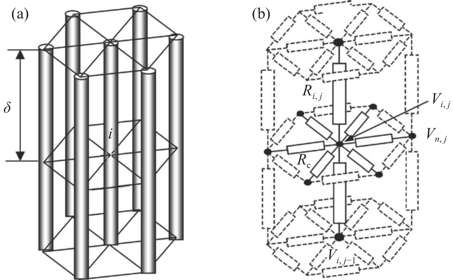
Park等[49, 67]和Xia等[68]考虑纤维接触点的影响,引入了电无效长度
δec (Electrical ineffective length)参数,从而建立了等效直流并联电阻模型(图13);同时结合Weibull强度理论和全局负荷分担(Global load sharing,GLS)模型建立了单向复合材料层压板一维力电耦合本构模型,并用蒙特卡洛法验证了该本构模型在拉伸作用下的有效性,最终将其成功应用于复合材料的损伤定量分析。在此研究的基础上,Ogi等[69]直接将接触电阻与碳纤维电阻串联,组成H型等效直流电路,建立了二维力电耦合本构模型,预测了拉伸作用下单向复合材料层压板的电阻变化,结果显示该模型能准确预测0°和90°层压板在低应变区线性压阻响应和高应变区非线性压阻响应;通过将灵敏度系数表示为偏轴角度的函数,发现当偏轴角度为12°时灵敏度系数达到最大值。Zhu等[70]考虑层间接触电阻的影响,建立了复合材料层压板梁厚度方向的并联电阻模型(图14),用以分析变形后碳纤维复合材料梁拉伸面和压缩面的电阻变化,结果表明在弯曲应力下,厚度方向的电导率增大,使电流沿厚度方向更容易渗透传导,从而在宏观上表现出与弯曲变形对应的压阻响应。Sevkat等[71]采用四探针法发现多向复合材料层压板的压阻行为与单向复合材料层压板不同,电阻变化呈明显的三段式:先增加、然后减小和最终的指数增加,其中电阻减小阶段是由于复合材料受拉时产生的泊松效应、高纤维体积含量和多角度铺层结构使内部纤维接触点增多,从而导致电导率增加;同时基于纤维接触点的Weibull分布函数和电导率指数函数建立了力电耦合统计模型,该模型可以准确预测上述3个阶段的压阻响应。Wang等[72]依据泊松效应、应变效应和损伤效应推导出了多向层压板沿纵向和厚度方向的二维力电耦合本构模型,并通过压缩实验进行了验证,结果表明随着压缩应变的增加,复合材料因内部损伤导致应变系数和灵敏度系数逐渐降低,变化趋势如图15所示。现有研究单/多向碳纤维复合材料层压板的力电耦合本构模型和适用条件见表2。![]()
![]()
![]() 表 2 单/多向复合材料层压板力电耦合本构模型Table 2. Electromechanical coupling constitutive model of unidirectional/multi-directional composite laminates
表 2 单/多向复合材料层压板力电耦合本构模型Table 2. Electromechanical coupling constitutive model of unidirectional/multi-directional composite laminatesDimension Resistance model Electromechanical coupling
constitutive modelRef. 1D Considering fiber contact resistance, the basic resistance unit is the electrical ineffective length, which is suitable for unidirectional laminates ΔRR=(1+αε)exp[−(δecLO)(Efεσ0)]−1 [67] 2D Considering fiber contact resistance, the basic resistance unit
is 1/2 of the ineffective length, suitable for unidirectional laminatesΔR11R11=1+K11ε11(1−F1)2−1(0∘)ΔR22R22=1+K22ε221−F2−1(90∘) [69] 1D Considering the fiber contact resistance, it follows Weibull statistical distribution; Conductivity, which follows a linear change before fiber fracture and an exponential change after fiber fracture, suitable for multi-directional laminates ΔRR=1 + eσ/σ0−1(ε⩽ [71] 2D Considering Poisson effect, strain effect, and damage effect, suitable for multi-directional laminates \begin{gathered}\upsilon = - \dfrac{{{\varepsilon _{11}}}}{{{\varepsilon _{33}}}},{\left( {\dfrac{{\Delta \rho }}{\rho }} \right)_{{\text{reversible}}}} = \alpha {\varepsilon _{33}} \\ \dfrac{{\Delta {R_{33}}}}{{{R_{33}}}} = {\varepsilon _{33}}(1 + \alpha + 2\upsilon ) \\ \dfrac{{\Delta {R_{11}}}}{{{R_{11}}}} = \dfrac{{\Delta {\rho _{11}}}}{{{\rho _{11}}}} - \dfrac{{{{\Delta {R_{33}}} \mathord{\left/ {\vphantom {{\Delta {R_{33}}} {{R_{33}}}}} \right. } {{R_{33}}}}}}{{1 + \alpha + 2\upsilon }} \\ {\left( {\dfrac{{\Delta \rho }}{\rho }} \right)_{{\text{irreversible}}}} = \beta {\varepsilon _{33}} \\ \end{gathered} [72] Notes: \Delta R—Resistance change rate; R—Resistance; \alpha —Gage factor; \varepsilon —Strain; {\delta _{{\text{ec}}}}—Slip length; {E_{\text{f}}}—Tensile modulus; L—Sample length; {L_{\text{O}}}—Reference length; {\sigma _{\text{0}}}—Weibull scale factor; K—Strain coefficient; {F_{\text{1}}}—Failure probability of series resistor components; {F_{\text{2}}}—Probability of failure of parallel resistor components; S—Loading stress; {S_{\text{0}}}—Reference stress; \Delta \rho —Resistivity change rate; \rho —Resistivity; υ—Poisson's ratio; b—Constant, 0.973; t—Constant,8.67; β—Damage effect coefficient. 4.2 二维增强结构复合材料力电耦合行为研究进展
对于二维增强结构复合材料,Nishio等[73]研究了平纹机织复合材料层压板在拉伸循环加载下的压阻响应,发现电阻随着循环次数的增加而减小,这是由于剪切变形引起厚度减小,从而导致层间纤维间的接触点增多。Rou等[74]采用实验和有限元分析相互验证的方法,研究了平纹机织碳纤维复合材料和碳/玻混杂复合材料层压板I型层间裂纹传播的规律,结果发现碳纤维层压板在裂纹起始传播时电阻增加变缓,而在裂纹沿中性层传播时电阻开始线性增加直至发生破坏,而且表面电极比内部电极感测的电阻变化对裂纹长度和载荷变化更加敏感。碳/玻混杂层压板由于混杂效应导致弹性模量减小,在同等变形条件下电阻增大,因而在裂纹传播时电阻变化十分明显。结果还表明,压阻行为对电极埋设的位置不敏感,因此更适于裂纹监测;有限元分析结果进一步表明,高电势和电流密度主要集中在裂纹尖端。Alsaadi等[75]研究了纤维体积含量和电极尺寸对斜纹机织复合材料层压板冲击损伤后电阻变化的影响,发现高纤维体积含量有助于提高复合材料厚度方向的电导率,同时小电极会增大流经材料表面的电流密度,在上述两者的共同作用下可以显著提高电阻变化和电阻监测的灵敏度。
4.3 三维增强结构复合材料力电耦合行为研究进展
对于三维增强结构复合材料,Saleh等[13]研究了三维机织AI结构(正交、层层和贯穿厚度)经向和偏轴角度(0°和45°)在拉伸作用下对力电耦合行为的影响,结果发现正交AI的偏轴方向由于材料内部纱线沿加载方向重新取向,发生大变形并形成有效的导电通路,导致拉伸破坏应变最大,电阻呈现出先增大后减小的变化趋势;层层AI的偏轴方向由于材料内部纱线、树脂分层引起了局部损伤,电阻变化最大。Wan等[76]采用四探针法研究了三维四向编织碳纤维复合材料的力电耦合行为,发现电阻在拉伸应变较小时呈现出线性增加的变化规律,当拉伸应变超过6%时,电阻则呈现出非线性增加;循环压缩实验表明电阻随着压缩比和循环次数的增加而线性增加。Cheng等[77]研究了碳/芳纶混杂三维机织正交AI复合材料在弯曲循环加载下的压阻响应,发现在低挠度下复合材料表现出了负压阻效应,在高挠度下表现出了正压阻效应,且位于中间位置处的碳纤维长丝束电阻变化最大。Han等[11]利用四探针法研究了不同偏轴角度的三维机织AI复合材料在短梁剪切准静态和循环加载下的电阻响应, 发现三维机织AI复合材料的力电耦合行为对偏轴角度十分敏感:在准静态加载过程中,轴向试样因纱线断裂导致内部导电通路发生中断,电阻直线增加;偏轴试样因内部纱线发生重新取向和分离,导电网络经历破坏和重组的变化过程,电阻增加缓慢,最终保持恒定;在相同载荷循环加载下,复合材料由于压阻效应,相对电阻变化(
\Delta R )为负值并可逆地降低,其中0°轴向试样的\Delta R 变化最小,45°和60°偏轴试样的\Delta R 分别显示出最大的变化值和变化幅度,如图16所示。薛有松等[14]研究了三维机织 AI复合材料经、纬向在弯曲作用下的压阻响应,实验发现在弯曲疲劳加载前期,复合材料呈现出负压阻效应,基体裂纹、界面脱粘等不可逆的损伤随着循环次数的增加不断累积,导致电阻缓慢增加;在弯曲疲劳加载后期,电阻显著增加,这主要是由于主承载纱线的断裂所致(图17)。![]()
综上,现有对复合材料力电耦合行为的研究多处于实验分析和唯象描述,而且已建立的力电耦合解析模型只适用于单向复合材料的预测,对分析预测不同维度增强结构复合材料的力电耦合行为适用性较差,缺少系统地分析。
5. 结 论
从整体来看,当前国内外对碳纤维树脂基复合材料的电导率、电势场分布和力电耦合行为的研究还处于探索阶段,缺乏行之有效的预测模型分析碳纤维复合材料内部的导电机制。尤其是在三维增强结构复合材料中,纱线相互交织成为一个整体,而且内部的纱线截面形态和路径变化更加复杂,研究难度进一步增加。因此下一阶段的主要任务和努力方向包括:
(1) 深入研究不同增强结构碳纤维树脂基复合材料的电导率、电势场分布和力电耦合行为,系统揭示复合材料导电机制的结构效应和传导路径差异;
(2) 结合电阻抗成像技术、电网络理论和机器学习等新技术,为研究三维增强结构碳纤维树脂基复合材料的电导特性和力电耦合行为提供新思路和新方案;
(3) 在构建碳纤维树脂基复合材料力电耦合本构模型时,应准确表征碳纤维复合材料在加载条件下电阻响应和刚度退化之间的定量关系,明晰导电网络的变形、破坏和重组等变化过程,最终实现碳纤维复合材料导电结构的优化设计和智能监测的有效利用。
-
![]()
图 1 碳纤维复合材料在结构健康监测(SHM)中的应用:(a) 力电耦合行为;(b) 导电机制;(c) 飞机机翼监测;(d) 桥梁承载监测
Figure 1. Application of carbon fiber composites in structural health monitoring (SHM): (a) Electromechanical coupling behavior; (b) Conductive mechanism; (c) Aircraft wing monitoring; (d) Bridge bearing monitoring
ΔR—Relative resistance change; R0—Initial resistance; σ1—Stress; ε1—Strain
![]()
图 2 复合材料不同维度增强体结构
Figure 2. Different dimensional reinforcement structure of composites
![]()
图 3 复合材料内部电流传导路径示意图
Figure 3. Schematic diagram of internal current conduction path of composites
![]()
![]()
图 5 缎纹机织复合材料层压板电导率多尺度均质模型分析[40]
Figure 5. Multi-scale homogeneous model analysis of electrical conductivity of satin woven composite laminates[40]
[σ]yarn—Yarn conductivity; Rx, Ry, Rz—Resistance in the x, y and z directions of Unit 2; Reqx, Reqy, Reqz—Equivalent resistance of single-layer composite materials in the x, y and z directions
![]()
图 6 不同铺层结构碳纤维复合材料层压板电势场和温度场分布[47]
Figure 6. Distribution of electric potential field and temperature field of carbon fiber composite laminates with different laminate structures[47]
J—Electrical current; φ*—Electrical potential field; E*—Electrical field component; Q*—Heat flux; T*—Temperature; T*image—Thermal imaging temperature
![]()
![]()
![]()
![]()
![]()
![]()
![]()
![]()
![]()
表 1 单向复合材料层压板电导率预测模型
Table 1 Prediction model for electrical conductivity of unidirectional composite laminates
Model Electrical conductivity prediction model Ref. Longitudinal direction Transverse direction Thickness direction Haider model (Composites containing conductive particles) {\sigma _{{{xx}}}} = {\sigma _{\text{f}}}{V_{\rm{f}}} + {\sigma _{\rm{m}}}(1 - {V_{\rm{f}}}) {\sigma _{{{yy}}}} = {\sigma _{zz}}{\text{ = }}{\sigma _{\text{m}}}\dfrac{{{\sigma _{\rm{f}}}(1 + {V_{\rm{f}}}) + {\sigma _{\text{m}}}(1 - {V_{\rm{f}}})}}{{{\sigma _{\rm{f}}}(1 - {V_{\rm{f}}}) + {\sigma _{\text{m}}}(1 + {V_{\rm{f}}})}} [34] Penetration model(Unidirectional composite) {\sigma _{{{zz}}}}{\text{ = }}{\sigma _{\rm{f}}}{\left( {{V_{\rm{f}}} - {V_{\rm{c}}}} \right)^{{p}}} [35] Bueche model(Composites containing conductive particles) {\sigma _{{{xx}}}} = \dfrac{{{{(1 - {V_{\rm{f}}})} /{{\sigma _{\rm{f}}} + {{{V_{\rm{f}}}{w_{\rm{g}}}} / {{\sigma _{\rm{m}}}}}}}}}{{{1 /{{\sigma _{\rm{m}}}{\sigma _{\rm{f}}}}}}} [36] Fiber contact model(Multidirectional composites containing angle layers) {\sigma _{ { {xx} } } } = \dfrac{ { {\text{π} } {d^2}X} }{ {4{ \sigma_{\text{f} } }{V_{\rm{p} } }{d_{\rm{c} } }l{\cos^2}\theta } } {\sigma _{{\text{yy}}}} = \dfrac{{{\text{π}} {d^2}X}}{{4{\sigma _{{\rm{f}}}}{V_{\rm{p}}}{d_{\rm{c}}}l{\text{si}}{{\text{n}}^2}\theta }} [37] Fiber inclination model(Multidirectional composites containing angle layers) {\sigma _{ { {xx} } } } = {\sigma _{\rm{f} } }{V_{\text{f} } }\cos{^2}\theta \left(1 - \dfrac{ {L\tan \theta } }{W}\right) {\sigma _{ { {yy} } } } = {\sigma _{\rm{f} } }{V_{\text{f} } }{\text{si} }{ {\text{n} }^2}\theta \left(1 - \dfrac{ {L\cot \theta } }{W}\right) [37] Effective medium model(Unidirectional composite) {\sigma _{{{xx}}}} = {\sigma _{\rm{m}}}\left[ {1 + \dfrac{{{V_{\rm{f}}}({\sigma _{\rm{f}}} - {\sigma _{\rm{m}}})\left[ {({\sigma _{\rm{f}}} - {\sigma _{\rm{m}}})\left( {{S_{11}} + {S_{33}}} \right) + 2{\sigma _{\rm{m}}}} \right]}}{{2{{({\sigma _{\rm{f}}} - {\sigma _{\rm{m}}})}^2}(1 - {V_{\rm{f}}}){S_{11}}{S_{33}} + {\sigma _{\rm{m}}}({\sigma _{\rm{f}}} - {\sigma _{\rm{m}}})(2 - {V_{\rm{f}}})({S_{11}} - {S_{33}})}}} \right] [38] McCullough model(Composites containing conductive particles) {\sigma _{ { {ii} } } } = {V_{\rm{f} } }{\sigma _{\rm{f} } } + {V_{\rm{m} } }{\sigma _{\rm{m} } } - \dfrac{ { {\lambda _i}{V_{\rm{f} } }{V_{\rm{m} } }{ {({\sigma _{\rm{f} } } - {\sigma _{\rm{m} } })}^2} } }{ { {V_{ { {{\rm{f}}i} } } }{\sigma _{\rm{f} } } + {V_{ { {{\rm{m}}i} } } }{\sigma _{\rm{m} } } } }
{V_{{{\rm{f}}}}}_{{i}} = (1 - {\lambda _i}){V_{\text{f}}} + {\lambda _i}{V_{\text{m}}},{V_{\text{m}}}_{{i}} = (1 - {\lambda _i}){V_{\text{m}}} + {\lambda _i}{V_{\text{f}}}, i=1, 2, 3[39] Notes: {\sigma _{\text{f}}}—Fiber conductivity; {\sigma _{\text{m}}}—Resin conductivity; {V_{\text{f}}}—Fiber volume fraction; {V_{\text{c} } }—Critical fiber volume fraction; p—Critical exponent; {w_{\text{g} } }—Conductive particle content; d—Fiber diameter; {d_{\text{c}}}—Fiber contact circle diameter; X—Fiber contact coefficient; l—Fiber length; {V_{\text{p}}}—Contact fiber volume; L—Sample length; W—Sample width; \theta —Fiber inclination angle; S—Shape parameter; x, y, z—Coordinate direction; 1, 2, 3—Principal axis direction; {\lambda _{{{{i}}} } }—Fiber contact factor; σxx, σyy, σzz—Electrical conductivity in the x, y and z directions; σii—Conductivity component.  下载: 导出CSV
表 2 单/多向复合材料层压板力电耦合本构模型
Table 2 Electromechanical coupling constitutive model of unidirectional/multi-directional composite laminates
Dimension Resistance model Electromechanical coupling
constitutive modelRef. 1D Considering fiber contact resistance, the basic resistance unit is the electrical ineffective length, which is suitable for unidirectional laminates \dfrac{ {\Delta R} }{R} = \dfrac{ {(1 + \alpha \varepsilon )} }{ {\exp\left[ { - \left(\dfrac{ { {\delta _{\rm ec} } } }{ { {L_{\rm{O}}} } }\right)\left(\dfrac{ { {E_{\rm{f} } }\varepsilon } }{ { {\sigma _0} } }\right)} \right]} }{ { - } }1 [67] 2D Considering fiber contact resistance, the basic resistance unit
is 1/2 of the ineffective length, suitable for unidirectional laminates\begin{gathered} \dfrac{{\Delta {R_{11}}}}{{{R_{11}}}} = \dfrac{{1 + K{}_{11}{\varepsilon _{11}}}}{{{{\left( {1 - {F_1}} \right)}^2}}} - 1(0^\circ ) \\ \dfrac{{\Delta {R_{22}}}}{{{R_{22}}}} = \dfrac{{1 + K{}_{22}{\varepsilon _{22}}}}{{1 - {F_2}}} - 1(90^\circ ) \\ \end{gathered} [69] 1D Considering the fiber contact resistance, it follows Weibull statistical distribution; Conductivity, which follows a linear change before fiber fracture and an exponential change after fiber fracture, suitable for multi-directional laminates \begin{gathered} \dfrac{ {\Delta R} }{R} = \dfrac{ { {\text{1 + e} } } }{ { {\sigma / { {\sigma _{\rm 0} } } } } } - 1(\varepsilon \leqslant 10\% ) \\ \dfrac{ {\Delta R} }{R} = \dfrac{ { {\text{1 + e} } } }{ {b{ {\rm e}^{ - { {(S - {S_0})}^t} } } }} - 1(\varepsilon \leqslant 10\% ) \\ \end{gathered} [71] 2D Considering Poisson effect, strain effect, and damage effect, suitable for multi-directional laminates \begin{gathered}\upsilon = - \dfrac{{{\varepsilon _{11}}}}{{{\varepsilon _{33}}}},{\left( {\dfrac{{\Delta \rho }}{\rho }} \right)_{{\text{reversible}}}} = \alpha {\varepsilon _{33}} \\ \dfrac{{\Delta {R_{33}}}}{{{R_{33}}}} = {\varepsilon _{33}}(1 + \alpha + 2\upsilon ) \\ \dfrac{{\Delta {R_{11}}}}{{{R_{11}}}} = \dfrac{{\Delta {\rho _{11}}}}{{{\rho _{11}}}} - \dfrac{{{{\Delta {R_{33}}} \mathord{\left/ {\vphantom {{\Delta {R_{33}}} {{R_{33}}}}} \right. } {{R_{33}}}}}}{{1 + \alpha + 2\upsilon }} \\ {\left( {\dfrac{{\Delta \rho }}{\rho }} \right)_{{\text{irreversible}}}} = \beta {\varepsilon _{33}} \\ \end{gathered} [72] Notes: \Delta R—Resistance change rate; R—Resistance; \alpha —Gage factor; \varepsilon —Strain; {\delta _{{\text{ec}}}}—Slip length; {E_{\text{f}}}—Tensile modulus; L—Sample length; {L_{\text{O}}}—Reference length; {\sigma _{\text{0}}}—Weibull scale factor; K—Strain coefficient; {F_{\text{1}}}—Failure probability of series resistor components; {F_{\text{2}}}—Probability of failure of parallel resistor components; S—Loading stress; {S_{\text{0}}}—Reference stress; \Delta \rho —Resistivity change rate; \rho —Resistivity; υ—Poisson's ratio; b—Constant, 0.973; t—Constant,8.67; β—Damage effect coefficient.
下载: 导出CSV
-
[1] LLORCA J, GONZALEZ C, MOLINA-ALDAREGUIA J M, et al. Multiscale modeling of composite materials: A roadmap towards virtual testing[J]. ChemInform, 2011, 23: 5130-5147.
[2] 王晓旭, 张典堂, 钱坤, 等. 深海纤维增强树脂复合材料圆柱耐压壳力学性能的研究进展[J]. 复合材料学报, 2020, 37(1): 16-26. WANG X X, ZHANG D T, QIAN K, et al. Research progress on mechanical properties of deep-seafiber reinforced resin composite cylindrical pressureshells[J]. Acta Materiae Compositae Sinica, 2020, 37(1): 16-26(in Chinese).
[3] HUANG Z M, LI P. Prediction of laminate delamination with no iteration[J]. Engineering Fracture Mechanics, 2020, 238: 107248.
[4] GE L, LI H, ZHONG J, et al. Micro-CT based trans-scale damage analysis of 3D braided composites with pore defects[J]. Composites Science and Technology, 2021, 211: 108830.
[5] KE Y, HUANG S, GUO J, et al. Effects of thermo-oxidative aging on 3-D deformation field and mechanical behaviors of 3-D angle-interlock woven composites[J]. Composite Structures, 2022, 281: 115116.
[6] IRFAN M S, KHAN T, HUSSAIN T, et al. Carbon coated piezoresistive fiber sensors: From process monitoring to structural health monitoring of composites—A review[J]. Composites Part A: Applied Science and Manufacturing, 2021, 141: 106236.
[7] GONZÁLEZ C, VILATELA J J, MOLINA-ALDAREGUÍA J M, et al. Structural composites for multifunctional applications: Current challenges and future trends[J]. Progress in Materials Science, 2017, 89: 194-251.
[8] CHUNG D D L. A review of multifunctional polymer-matrix structural composites[J]. Composites Part B: Engineering, 2019, 160: 644-660.
[9] ROH H D, OH S Y, PARK Y B. Self-sensing impact damage in and non-destructive evaluation of carbon fiber-reinforced polymers using electrical resistance and the corresponding electrical route models[J]. Sensors and Actuators A: Physical, 2021, 332: 112762.
[10] MATSUZAKI R, YAMAMOTO K, TODOROKI A. Delamination detection in carbon fiber reinforced plastic cross-ply laminates using crack swarm inspection: Experimental verification[J]. Composite Structures, 2017, 173: 127-135.
[11] HAN C, HUANG S, SUN B, et al. Electrical resistance changes of 3D carbon fiber/epoxy woven composites under short beam shear loading along different orientations[J]. Composite Structures, 2021, 276: 114549.
[12] CAN-ORTIZ A, ABOT J L, AVILÉS F. Electrical characterization of carbon-based fibers and their application for sensing relaxation-induced piezoresistivity in polymer composites[J]. Carbon, 2019, 145: 119-130.
[13] SALEH M N, YUDHANTO A, LUBINEAU G, et al. The effect of z-binding yarns on the electrical properties of 3D woven composites[J]. Composite Structures, 2017, 182: 606-616.
[14] 薛有松, 薛凌明, 孙宝忠, 等. 碳纤维三维角联锁机织复合材料弯曲作用下力阻响应[J]. 复合材料学报, 2023, 40(3): 1468-1476. XUE Y S, XUE L M, SUN B Z, et al. Piezoresistive effect of carbon fiber 3D angle-interlock woven composites under bending[J]. Acta Materiae Compositae Sinica, 2023, 40(3): 1468-1476(in Chinese).
[15] SELVAKUMARAN L, LONG Q, PRUDHOMME S, et al. On the detectability of transverse cracks in laminated composites using electrical potential change measurements[J]. Composite Structures, 2015, 121: 237-246.
[16] BOUSSU F, CRISTIAN I, NAUMAN S. General definition of 3D warp interlock fabric architecture[J]. Composites Part B: Engineering, 2015, 81: 171-188.
[17] YU H, SUN J, HEIDER D, et al. Experimental investigation of through-thickness resistivity of unidirectional carbon fiber tows[J]. Journal of Composite Materials, 2019, 53: 2993-3003.
[18] JIANG M, CONG X, YI X, et al. A stochastic overlap network model of electrical properties for conductive weft yarn composites and their experimental study[J]. Composites Science and Technology, 2022, 217: 109075.
[19] WINTIBA B, VASIUKOV D, PANIER S, et al. Automated reconstruction and conformal discretization of 3D woven composite CT scans with local fiber volume fraction control[J]. Composite Structures, 2020, 248: 112438.
[20] ISAAC-MEDINA B, ALONZO-GARCÍA A, AVILÉS F. Electrical self-sensing of impact damage in multiscale hierarchical composites with tailored location of carbon nanotube networks[J]. Structural Health Monitoring, 2019, 18: 806-818.
[21] YU H, HEIDER D, ADVANI S. A 3D microstructure based resistor network model for the electrical resistivity of unidirectional carbon composites[J]. Composite Structures, 2015, 134: 740-749.
[22] LOUIS M, JOSHI S P, BROCKMANN W. An experimental investigation of through-thickness electrical resistivity of CFRP laminates[J]. Composites Science and Technology, 2001, 61: 911-919.
[23] HAN C, SUN B, GU B. Electric conductivity and surface potential distributions in carbon fiber reinforced composites with different ply orientations[J]. Textile Research Journal, 2022, 92: 1147-1160.
[24] ABRY J C, BOCHARD S, CHATEAUMINOIS A, et al. In situ detection of damage in CFRP laminates by electrical resistance measurements[J]. Composites Science and Technology, 1999, 59: 925-935.
[25] TODOROKI A, TANAKA M, SHIMAMURA Y. Measurement of orthotropic electric conductance of CFRP laminates and analysis of the effect on delamination monitoring with an electric resistance change method[J]. Composites Science and Technology, 2002, 62: 619-628.
[26] WASSELYNCK G, TRICHET D, FOULADGAR J. Determination of the electrical conductivity tensor of a CFRP composite using a 3-D percolation model[J]. IEEE Transactions on Magnetics, 2013, 49: 1825-1828.
[27] KANE B, PIERQUIN A, WASSELYNCK G, et al. Coupled numerical and experimental identification of geometrical parameters for predicting the electrical conductivity of CFRP layers[J]. IEEE Transactions on Magnetics, 2020, 56: 6701604.
[28] XIAO J, LI Y, FAN W X. A laminate theory of piezoresistance for composite laminates[J]. Composites Science and Technology, 1999, 59: 1369-1373.
[29] TODOROKI A. Electric current analysis for thick laminated CFRP composites[J]. Transactions of the Japan Society for Aeronautical and Space Sciences, 2012, 55: 237-243.
[30] YAMANE T, TODOROKI A. Analysis of electric current density in carbon fiber reinforced plastic laminated plates with angled plies[J]. Composite Structures, 2017, 166: 268-276.
[31] ATHANASOPOULOS N, KOSTOPOULOS V. A comprehensive study on the equivalent electrical conductivity tensor validity for thin multidirectional carbon fibre reinforced plastics[J]. Composites Part B: Engineering, 2014, 67: 244-255.
[32] BENSAID S, TRICHET D, FOULADGAR J. Electrical conductivity identification of composite materials using a 3-D anisotropic shell element model[J]. IEEE Transactions on Magnetics, 2009, 45: 1859-1862.
[33] CHENG J, JI H, TAKAGI T, et al. Role of interlaminar interface on bulk conductivity and electrical anisotropy of CFRP Laminates measured by eddy current method[J]. NDT & E International, 2014, 68: 1-12.
[34] HAIDER M F, HAIDER M M, YASMEEN F. Micromechanics model for predicting anisotropic electrical conductivity of carbon fiber composite materials[J]. AIP Conference Proceedings, 2016, 1754: 030011.
[35] VILČÁKOVÁ J, SÁHA P, QUADRAT O. Electrical conductivity of carbon fibres/polyester resin composites in the percolation threshold region[J]. European Polymer Journal, 2002, 38: 2343-2347.
[36] AHARONI S M. Electrical resistivity of a composite of conducting particles in an insulating matrix[J]. Journal of Applied Physics, 1972, 43: 2463-2465.
[37] WEBER M, KAMAL M R. Estimation of the volume resistivity of electrically conductive composites[J]. Polymer Composites, 1997, 18: 711-725.
[38] TAYA M, UEDA N. Prediction of the in-plane electrical conductivity of a misoriented short fiber composite: Fiber percolation model versus effective medium theory[J]. Journal of Engineering Materials and Technology-Transactions of the Asme, 1987, 109: 252-256.
[39] BERGER M A, MCCULLOUGH R L. Characterization and analysis of the electrical properties of a metal-filled polymer[J]. Composites Science and Technology, 1985, 22: 81-106.
[40] SENGHOR F, WASSELYNCK G, HUU KIEN B, et al. Electrical conductivity tensor modeling of stratified woven-fabric carbon fiber reinforced polymer composite materials[J]. IEEE Transactions on Magnetics, 2017, 53: 9401604.
[41] BALTOPOULOS A, POLYDORIDES N, PAMBAGUIAN L, et al. Damage identification in carbon fiber reinforced polymer plates using electrical resistance tomography mapping[J]. Journal of Composite Materials, 2013, 47: 3285-3301.
[42] HAN C, SUN B, GU B. Electric potential distributions in carbon fiber/epoxy plain-woven laminates with different current directions[J]. Composite Structures, 2021, 270: 114059.
[43] 石荣荣, 武宝林. 三维编织碳纤维复合材料电阻率的估算[J]. 复合材料学报, 2016, 33(12): 2775-2780. SHI R R, WU B L. Resistivity estimation of 3D braided carbon fiber composites[J]. Acta Materiae Compositae Sinica, 2016, 33(12): 2775-2780(in Chinese).
[44] WANG D, CHUNG D D L. Comparative evaluation of the electrical configurations for the two-dimensional electric potential method of damage monitoring in carbon fiber polymer-matrix composite[J]. Smart Materials and Structures, 2006, 15: 1332-1344.
[45] ANGELIDIS N, KHEMIRI N, IRVING P E. Experimental and finite element study of the electrical potential technique for damage detection in CFRP laminates[J]. Smart Materials and Structures, 2004, 14: 147-154.
[46] ANGELIDIS N, IRVING P E. Detection of impact damage in CFRP laminates by means of electrical potential techniques[J]. Composites Science and Technology, 2007, 67: 594-604.
[47] ATHANASOPOULOS N, KOSTOPOULOS V. Resistive heating of multidirectional and unidirectional dry carbon fibre preforms[J]. Composites Science and Technology, 2012, 72: 1273-1282.
[48] BUSCH R, RIES G, WERTHNER H, et al. New aspects of the mixed state from six-terminal measurements on Bi2Sr2CaCu2Ox single crystals[J]. Physical Review Letters, 1992, 69: 522-525.
[49] PARK J B, OKABE T, TAKEDA N. New concept for modeling the electromechanical behavior of unidirectional carbon-fiber-reinforced plastic under tensile loading[J]. Smart Materials and Structures, 2003, 12: 105-114.
[50] TODOROKI A. Electric current analysis of CFRP using perfect fluid potential flow[J]. Journal of The Japan Society for Aeronautical and Space Sciences, 2012, 55: 183-190.
[51] YAMANE T, TODOROKI A. Electric potential function of oblique current in laminated carbon fiber reinforced polymer composite beam[J]. Composite Structures, 2016, 148: 74-84.
[52] YAMANE T, TODOROKI A, FUJITA H, et al. Electric current distribution of carbon fiber reinforced polymer beam: Analysis and experimental measurements[J]. Advanced Composite Materials, 2016, 25: 497-513.
[53] LEE I Y, ROH H D, PARK Y B. Novel structural health monitoring method for CFRPs using electrical resistance based probabilistic sensing cloud[J]. Composites Science and Technology, 2021 ,213: 108812.
[54] KIKUNAGA K, TERASAKI N. Characterization of electrical conductivity of carbon fiber reinforced plastic using surface potential distribution[J]. Japanese Journal of Applied Physics, 2018, 57: 04 FC02.
[55] GAIER J R, YODERVANDENBERG Y, BERKEBILE S, et al. The electrical and thermal conductivity of woven pristine and intercalated graphite fiber-polymer composites[J]. Carbon, 2003, 41: 2187-2193.
[56] 韩朝锋. 碳纤维复合材料电导率、电势分布及力电耦合行为[D]. 上海: 东华大学, 2022. HAN C F. Electrical conductivity, potential distributions and electromechanical coupling behavior of carbon fiber composites[D]. Shanghai: Donghua University, 2022(in Chinese).
[57] CHUNG D D L. A critical review of piezoresistivity and its application in electrical-resistance-based strain sensing[J]. Journal of Materials Science, 2020, 55: 15367-15396.
[58] WANG S, CHUNG D, CHUNG J. Self-sensing of damage in carbon fiber polymer-matrix composite by measurement of the electrical resistance or potential away from the damaged region[J]. Journal of Materials Science, 2005, 40: 6463-6472.
[59] WANG S, CHUNG D D L, CHUNG J H. Impact damage of carbon fiber polymer–matrix composites, studied by electrical resistance measurement[J]. Composites Part A: Applied Science and Manufacturing, 2005, 36: 1707-1715.
[60] WANG S, CHUNG D D L, CHUNG J H. Self-sensing of damage in carbon fiber polymer-matrix composite cylinder by electrical resistance measurement[J]. Journal of Intelligent Material Systems and Structures, 2006, 17: 57-62.
[61] LEONG C K, WANG S, CHUNG D D L. Effect of through-thickness compression on the microstructure of carbon fiber polymer-matrix composites, as studied by electrical resistance measurement[J]. Journal of Materials Science, 2006, 41: 2877-2884.
[62] WANG D, WANG S, CHUNG D D L, et al. Comparison of the electrical resistance and potential techniques for the self-sensing of damage in carbon fiber polymer-matrix composites[J]. Journal of Intelligent Material Systems and Structures, 2006, 17: 853-861.
[63] WANG D, CHUNG D D L. Through-thickness stress sensing of a carbon fiber polymer-matrix composite by electrical resistance measurement[J]. Smart Materials and Structures, 2007, 16: 1320-1330.
[64] ANGELIDIS N, WEI C Y, IRVING P E. The electrical resistance response of continuous carbon fibre composite laminates to mechanical strain[J]. Composites Part A: Applied Science and Manufacturing, 2004, 35: 1135-1147.
[65] WEN S, CHUNG D D L. Electrical-resistance-based damage self-sensing in carbon fiber reinforced cement[J]. Carbon, 2007, 45: 710-716.
[66] KWON D J, SHIN P S, KIM J H, et al. Detection of damage in cylindrical parts of carbon fiber/epoxy composites using electrical resistance (ER) measurements[J]. Composites Part B: Engineering, 2016, 99: 528-532.
[67] PARK JB, OKABE T, TAKEDA N, et al. Electromechanical modeling of unidirectional CFRP composites under tensile loading condition[J]. Composites Part A: Applied Science and Manufacturing, 2002, 33: 267-275.
[68] XIA Z, OKABE T, PARK J B, et al. Quantitative damage detection in CFRP composites: Coupled mechanical and electrical models[J]. Composites Science and Technology, 2003, 63: 1411-1422.
[69] OGI K, TAKAO Y. Characterization of piezoresistance behavior in a CFRP unidirectional laminate[J]. Composites Science and Technology, 2005, 65: 231-239.
[70] ZHU S, CHUNG D D L. Analytical model of piezoresistivity for strain sensing in carbon fiber polymer-matrix structural composite under flexure[J]. Carbon, 2007, 45: 1606-1613.
[71] SEVKAT E, LI J, LIAW B, et al. A statistical model of electrical resistance of carbon fiber reinforced composites under tensile loading[J]. Composites Science and Technology, 2008, 68: 2214-2219.
[72] WANG D, CHUNG D D L. Through-thickness piezoresistivity in a carbon fiber polymer-matrix structural composite for electrical-resistance-based through-thickness strain sensing[J]. Carbon, 2013, 60: 129-138.
[73] NISHIO Y, TODOROKI A, MIZUTANI Y, et al. Piezoresistive effect of plain-weave CFRP fabric subjected to cyclic loading[J]. Advanced Composite Materials, 2017, 26: 229-243.
[74] ROH H D, LEE S Y, JO E, et al. Deformation and interlaminar crack propagation sensing in carbon fiber composites using electrical resistance measurement[J]. Composite Structures, 2019, 216: 142-150.
[75] ALSAADI A, MEREDITH J, SWAIT T, et al. Structural health monitoring for woven fabric CFRP laminates[J]. Composites Part B: Engineering, 2019, 174: 107048.
[76] WAN Z K, WANG Z G. Electrical characteristics of composite material under loading based on SQUID technology[J]. Journal of Textile Research, 2010, 31: 58-63.
[77] CHENG X, ZHOU H, WU Z, et al. An investigation into self-sensing property of hat-shaped 3D orthogonal woven composite under bending test[J]. Journal of Reinforced Plastics and Composites, 2019, 38: 149-166.
-
期刊类型引用(3)
1. 吴浩,王洪杰,王赫,苏永生,胡侨乐,阮芳涛. 碳纤维基太阳能驱动界面水蒸发器件研究进展. 复合材料学报. 2025(02): 692-703 .  本站查看
本站查看
2. 李子琪,裴纯,朱继华. 碳纤维增强水泥基复合材料界面优化设计研究进展. 复合材料学报. 2024(10): 5125-5145 . 本站查看
3. 王晨,王超,孙荣庆. 夹杂碳纤维的天线罩蒙皮在电磁场下的失效机理研究. 电子测量技术. 2024(23): 60-65 . 百度学术
其他类型引用(3)
-
目的
碳纤维及其复合材料作为国家战略新兴材料,因其轻质高强、高冲击损伤容限和多重增强结构混杂制造等特性,广泛应用在航空航天、远洋船舶、轨道交通和新能源汽车等高精尖技术领域。碳纤维复合材料除优异的损伤容限和热传导性能以外,突出的电导特性和压阻效应等多功能属性近年来逐步受到重视。碳纤维复合材料在外部承载下结构变形诱发电阻发生相应变化,本身可作为智能传感器件记录损伤演变过程,在实现结构材料承载的同时发挥功能材料自我感应的作用,在结构健康监测应用中具有巨大的潜在价值。因此研究和分析碳纤维树脂基复合材料不同维度增强体的电导特性与结构效应,揭示碳纤维复合材料的导电机理和力电耦合行为,对实现碳纤维复合材料在结构健康监测中的导电结构优化和高效配置,拓展碳纤维复合材料的多功能用途,具有重要的经济效益和应用价值。
方法电阻法利用碳纤维树脂基复合材料自身的压阻效应实现自我智能监测,无需依赖复杂的监测仪器和数据处理系统便可实现材料自身健康状态的原位监测,从而为复合材料损伤起始和积累过程提供精确实时的电信号信息。在复合材料增强体结构中,碳纤维纱线无序接触、穿插交织和屈曲变形,导致内部的电流传导路径随机分布,在复合材料中形成复杂的导电路径,从而对复合材料的电导性能产生重要影响。同时碳纤维复合材料的非均质特性,造成内部导电机理尚不清楚。本文从复合材料电阻法结构健康监测应用出发,着重概述了不同维度增强体碳纤维树脂基复合材料的导电性能和预测模型、表面电势场分布和主要测量技术,以及力电耦合行为和本构模型,以期为碳纤维复合材料“材料-结构-功能”一体化集成系统的设计提供新方向和新途径。
结果目前复合材料电导率的研究对象主要集中在传统层压复合材料,忽略铺层角度和层间界面电导率对导电性能的影响;对于三维增强结构复合材料的电导率仅限于实验测试,并未揭示复合材料内部的导电机理以及建立有效的导电模型。复合材料电势分布的研究主要局限于薄层复合材料层压板的表面,并未考虑电势沿厚度方向衰减的影响;而且对三维增强结构复合材料的电势分布研究较少,缺少空间电势分布的有效预测模型。现有对复合材料力电耦合行为的研究多处于实验分析和唯象描述,而且已建立的力电耦合解析模型只适用于单向复合材料的预测,对分析预测不同维度增强结构复合材料的力电耦合行为适用性较差,缺少系统地分析。
结论当前国内外对碳纤维树脂基复合材料的电导率、电势场分布和力电耦合行为的研究还处于探索阶段,缺乏行之有效的预测模型分析碳纤维复合材料内部的导电机理。尤其是在三维增强结构复合材料中,纱线相互交织成为一个整体,而且内部的纱线截面形态和路径变化更加复杂,研究难度进一步增加。因此下一阶段的主要任务和努力方向包括:(1)深入研究不同增强结构碳纤维树脂基复合材料的电导率、电势场分布和力电耦合行为,系统揭示复合材料导电机理的结构效应和传导路径差异;(2)结合电阻抗成像技术、电网络理论和机器学习等新技术,为研究三维增强结构碳纤维树脂基复合材料的电导特性和力电耦合行为提供新思路和新方案;(3)在构建碳纤维树脂基复合材料力电耦合本构模型时,应准确表征碳纤维复合材料在加载条件下电阻响应和刚度退化之间的定量关系,明晰导电网络的变形、破坏和重组等变化过程,最终实现碳纤维复合材料导电结构的优化设计和智能监测的有效利用。
-
碳纤维及其复合材料作为国家战略新兴材料,因其轻质高强、高冲击损伤容限和多重增强结构混杂制造等特性,广泛应用在航空航天、远洋船舶、轨道交通和新能源汽车等高精尖技术领域。碳纤维复合材料除优异的损伤容限和热传导性能以外,突出的电导特性和压阻效应等多功能属性近年来逐步受到重视。碳纤维复合材料在外部承载下结构变形诱发电阻发生相应变化,本身可作为智能传感器件记录损伤演变过程,在实现结构材料承载的同时发挥功能材料自我感应的作用,在结构健康监测(Structural health monitoring,SHM)应用中具有巨大的潜在价值。
本文从复合材料电阻法结构健康监测应用出发,着重概述了不同维度增强体碳纤维树脂基复合材料的导电性能和预测模型、表面电势场分布和主要测量技术,以及力电耦合行为和本构模型,以期为碳纤维复合材料“材料-结构-功能”一体化集成系统的设计提供新方向和新途径。针对现有研究现状,指出下一阶段的主要任务和努力方向包括:(1)深入研究不同增强结构碳纤维树脂基复合材料的电导率、电势场分布和力电耦合行为,系统揭示复合材料导电机理的结构效应和传导路径差异;(2)结合电阻抗成像技术、电网络理论和机器学习等新技术,为研究三维增强结构碳纤维树脂基复合材料的电导特性和力电耦合行为提供新思路和新方案;(3)在构建碳纤维树脂基复合材料力电耦合本构模型时,应准确表征碳纤维复合材料在加载条件下电阻响应和刚度退化之间的定量关系,明晰导电网络的变形、破坏和重组等变化过程,最终实现碳纤维复合材料导电结构的优化设计和智能监测的有效利用。
碳纤维复合材料(a)不同维度增强体结构和(b)内部电流传导路径示意图


计量
- 文章访问数: 1766
- HTML全文浏览量: 982
- PDF下载量: 289
- 被引次数: 6
