Study on calculation method of RC beam's shear bearing capacity of CFRP grid-polymer cement mortar
-
摘要: 为揭示碳纤维增强树脂复合材料(Carbon fiber reinforced polymer,CFRP)网格-聚合物水泥砂浆(Polymer cement mortar,PCM)抗剪加固钢筋混凝土(RC)梁的受剪机制并建立其承载力计算方法,对RC梁进行了四点弯曲试验和有限元模拟,重点分析了CFRP网格对RC加固梁的抗剪贡献,建立了基于改进的桁架拱模型的抗剪承载力计算方法。结果表明:RC梁侧粘贴CFRP网格-PCM加固层不仅可以抑制斜裂缝的发展,而且还提高了抗剪承载力;CFRP网格与钢筋之间具有良好的协同工作性能,其中,横向CFRP网格筋分担了约16%的箍筋应变;回归分析指出纵向CFRP网格筋的应变约为横向CFRP网格筋应变的0.29倍;综合考虑纵向CFRP网格的销栓作用和横向CFRP网格分担的箍筋应变,提出了基于改进桁架-拱模型的承载力计算方法,具有更好的适用性和准确性,能够满足设计要求。
-
关键词:
- CFRP网格-PCM抗剪加固RC梁 /
- 四点弯曲试验 /
- 有限元分析 /
- 改进的桁架-拱模型 /
- 承载力计算方法
Abstract: In order to reveal the shear mechanism of the carbon fiber reinforced polymer (CFRP) grid-polymer cement mortar (PCM) shear reinforced reinforced concrete (RC) beam and establish its bearing capacity calculation method, four-point bending tests and finite element simulation were conducted on the RC beams. The shear contribution of the CFRP grid to the RC reinforced RC beam was analyzed, and the shear bearing capacity calculation method was established based on the improved truss arch model. The results show that the CFRP grid-PCM reinforcement layer can not only inhibit the development of inclined cracks, but also improve the shear bearing capacity. CFRP grid and reinforcement have good cooperative working performance, where the horizontal CFRP grid shares about 16% of the stirrup strain. Regression analysis indicates that the strain of the vertical CFRP grid is about 0.29 times than that of the horizontal CFRP grid. Comprehensively considering the dowel action of the longitudinal CFRP grid and the stirrup strain shared by the horizontal CFRP grid, the bearing capacity calculation method is presented based on the improved truss-arch model, which has better applicability and accuracy to meet the design requirements. -
在环境、地震或其他灾害下,钢筋混凝土结构会产生性能退化或损伤破坏,需要对其进行加固维修。目前,常见的加固方式主要有增大截面加固法、外包型钢加固法、粘贴碳纤维材料加固法和间接性加固措施等[1]。其中在粘贴碳纤维材料加固法中,外贴碳纤维增强树脂复合材料(Carbon fiber reinforced polymer,CFRP)片材、内嵌CFRP棒材、预应力CFRP板加固等加固方式都采用环氧树脂作为界面粘结剂,具有在低温和潮湿环境下粘结性能差、与基材的相容性低、渗透性和耐久性差的等缺点,从而影响了纤维增强树脂复合材料(FRP)加固方法的有效性[2-5]。为了克服这些缺陷,一种新型、经济、可靠且高效的钢筋混凝土结构的加固方法被提出,即CFRP网格-聚合物水泥砂浆(Polymer cement mortar,PCM)加固方法[2]。
该加固方法是将CFRP网格用铆钉固定于经过真空喷砂处理后的既有混凝土表面,然后在混凝土与混凝土表面高压喷射PCM,使三者粘结成整体共同受力,提高结构的承载能力、刚度与耐久性能[2-3]。此加固方法加固层厚度较小,环境依赖度低,对结构使用空间影响小,且施工简单,施工效率高,极大地缩短了施工周期,有效地避免了钢板耐腐蚀性能差及在潮湿环境下与混凝土粘结性能差的缺陷[4]。
近年来,国内外研究学者已对CFRP网格加固钢筋混凝土(RC)结构的性能进行了大量研究。其中,在抗剪加固RC梁方面,Amiruddin[6]通过三点弯曲试验对比研究CFRP网格-PCM抗剪加固RC梁和未加固RC梁的抗剪性能影响规律,得出在既有RC梁中配置CFRP网格-PCM加固层能有效地提高RC梁的抗剪承载力。Khalifa[7]提出FRP材料在受力过程中产生的真实应变就是对极限应变进行一定折减获得的有效应变理论,因此,FRP网格的有效应变是确定FRP网格加固RC梁抗剪承载力的关键。曹亮等[8]通过参考《碳纤维片材加固混凝土结构技术规程》(CECS 146—2003)[9]中的方法,认为纤维网格的有效应变与加固梁的剪跨比之间有直接的关系,并提出了纤维编织网格增强地聚物砂浆加固梁抗剪承载力计算方法,但并未考虑到纤维编织网格增强地聚物砂浆加固层不同的破坏模式(加固层剥离、网格筋拉断及网格筋拔出)对纤维网格有效应变的影响。郑宇宙[10]虽然基于传统的钢筋混凝土梁的桁架拱受剪分析模型提出了纤维增强复合材料(Fiber reinforced polymer,FRP)网格增强工程用纤维增强水泥基复合材料(Engineered cementitious composite,ECC)抗剪加固RC梁的承载力计算方法,但在研究中忽略了FRP网格抗剪加固RC梁与普通RC梁在受剪机制上存在的差异而导致的受剪机制分析模型的适用性问题。Azam等[11]通过试验得出箍筋的存在会降低CFRP网格-PCM加固的有效性,考虑CFRP网格的有效应变取与临界斜裂缝相交位置的横向网格筋的平均应变,但未考虑到加固层剥离对有效应变的影响和CFRP网格与箍筋的协同工作性能的影响。陈文永等[12]通过对比分析碳纤维布加固RC梁、CFRP网格-聚合物砂浆加固RC梁的抗剪性能,提出CFRP网格的有效应变直接按极限抗拉强度折减30%来计算,该方法在确定折减系数时缺乏充分的解释和合理的理论依据。Guo等[13]通过数据回归分析拟合出的关于横向网格筋有效应变与网格配筋率之间的定量关系,计算出横向网格筋有效应变,但该法并没有全面分析影响CFRP网格有效应变的参数。
因此,本文以CFRP网格抗剪加固RC梁为研究对象,通过四点弯曲试验并结合有限元模拟对比分析,研究其受剪行为和受力性能影响因素,最后建立CFRP网格抗剪加固RC梁的受剪分析模型和抗剪承载力计算方法。
1. 试验概述
1.1 试件设计与制作
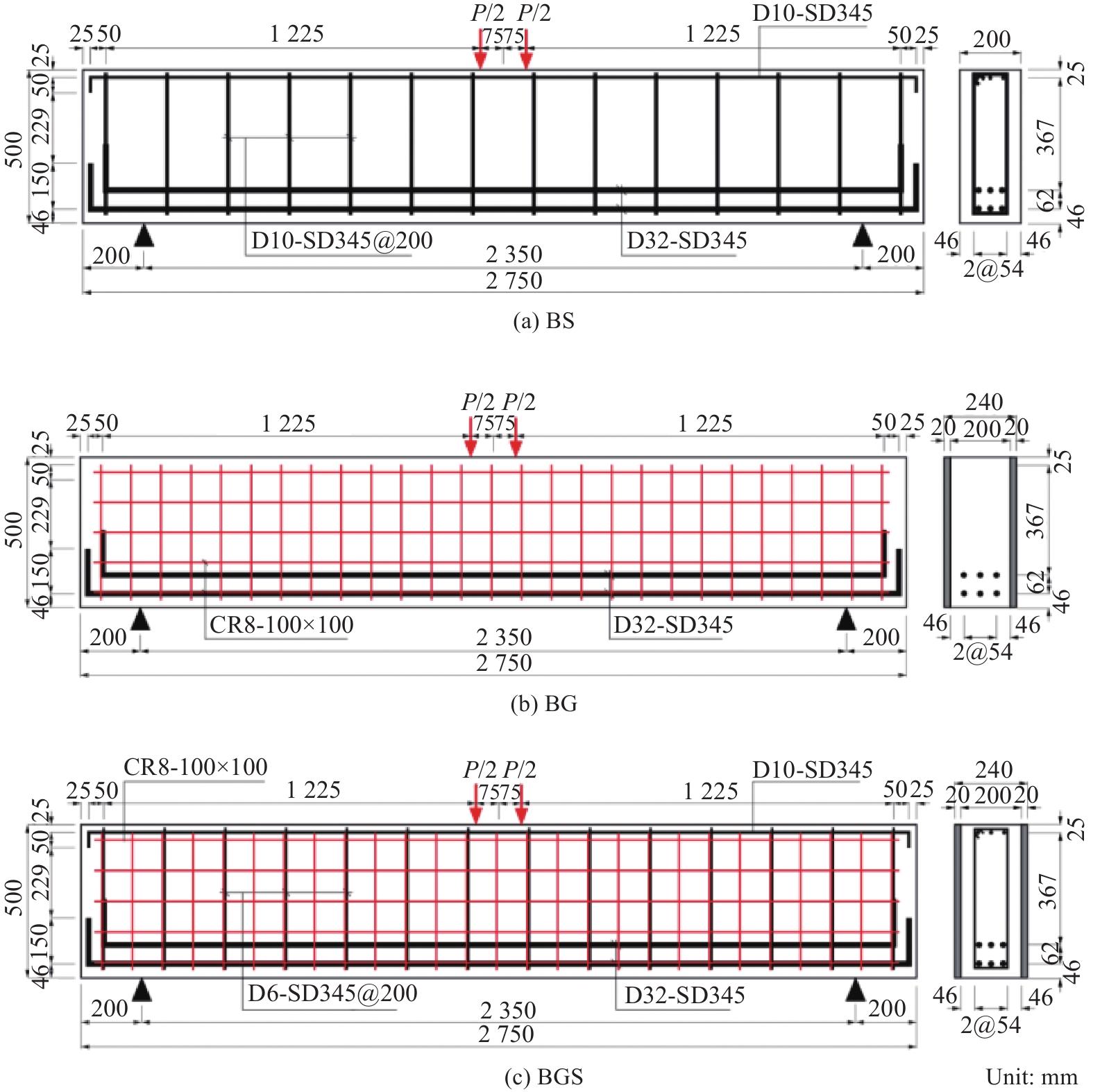
共设计了3根全跨长均为2750 mm,计算跨度为2350 mm,矩形截面为200 mm×500 mm的钢筋混凝土梁试件,编号分别为BS、BG和BGS(B表示钢筋混凝土梁,S表示梁内配有箍筋,G表示梁双侧粘贴CFRP网格-PCM加固层),其设计参数均采用日本混凝土结构设计标准[14],见表1。试件具体尺寸和配筋如图1所示,其中P为试验过程中所施加的荷载。为了避免先出现正截面受弯破坏,3个试件配置了足够的纵向钢筋。其中,BS梁底部受拉区配置6根D32纵向钢筋,顶部受压区配置2根D10纵向钢筋,沿梁全长内间距200 mm配置D10箍筋;BG梁底部配置6根D32纵向受拉钢筋但顶部受压区没有配置纵向钢筋,且在梁全长范围内没有配置箍筋;配置FRP网格加固层的BGS梁内纵向受力钢筋的配置情况与没有配置FRP网格加固层的BS梁相同,箍筋型号为D6。
表 1 试件设计Table 1. Specimen designSpecimen Existing steel bars FRP grid Shear
span λPCM thickness/
mmExisting vertical reinforcement ratio/% Anti-shear reinforcement ratio/% Tensile reinforcement Handling reinforcement Stirrup BS D32-SD345 D10-SD345 D10-SD345@200 — 2.63 — 5.8 0.36 BG D32-SD345 — — CR8-100×100 20 5.6 0.22 BGS D32-SD345 D10-SD345 D6-SD345@200 CR8-100×100 20 5.8 0.35 Notes: B—Reinforced concrete beam; S—Beam is equipped with stirrup; G—Stick carbon fiber reinforced polymer (CFRP) grid-polymer cement mortar (PCM) reinforcement layer on both sides; BS—Reinforced concrete beams provided with stirrups; BG—Reinforced concrete beam with only CFRP-PCM reinforced layer without stirrup; BGS—Reinforced concrete beams with stirrups and CFRP-PCM reinforcement layer; D—Diameter; SD—Reinforcement strength grade; CR8—CFRP grid of 8 mm in diameter; FRP—Fiber reinforced polymer. 试件的制作具体步骤如下:(1) 真空喷砂处理养护8天后的RC梁侧面后,将CFRP网格用铆钉临时固定在RC梁的两侧表面;(2) 当养护时间达到13天时,在CFRP网格和混凝土表面涂刷粘结剂,以防止在喷射PCM前,混凝土发生失水;(3) 高压喷射PCM到CFRP网格和混凝土表面,并在PCM表面涂刷固化剂。
1.2 材料性能
试件采用同一批次的预拌普通混凝土进行制作,混凝土28天龄期的立方体平均抗压强度为34.1 MPa,其配合比见表2。PCM由预混砂浆、聚合物和水组成,其材料性能在标准养护条件下养护7天后测试获得[15],混凝土和PCM的材料性能见表3。制作试件所采用的SD345型号的钢筋和网格筋间距为100 mm的CR8型号CFRP网格,其材料力学性能见表4。
表 2 混凝土配合比Table 2. Concrete mix proportionMaximum
grain size/mmColony/
mmWater cement
ratio/%Air ratio/% Measurement unit/(kg·m–3) Water Cement Fine aggregate Coarse aggregate Admixture 20 120 55.6 4.5 158 284 792 1126 1.3 表 3 混凝土和聚合物水泥砂浆(PCM)材料性能Table 3. Properties of concrete and polymer cement mortar (PCM) materialsMaterial Compression strength/MPa Tensile strength/MPa Modulus of elasticity/GPa Concrete 34.1 2.92 31.9 PCM 36.7 2.87 30.1 表 4 钢筋与碳纤维增强树脂复合材料(CFRP)网格的力学性能Table 4. Mechanical properties of steel and carbon fiber reinforced polymer (CFRP) gridsMaterial Type Cross-sectional area/mm2 Yield strength
/MPaModulus of elasticity/GPa Tensile strength
/MPaConcrete iron D32 794.2 389 200 587 D10 71.3 413 200 561 D6 31.7 417 200 570 CFRP grid CR8 26.4 — 100 1400 1.3 试验加载与量测方案
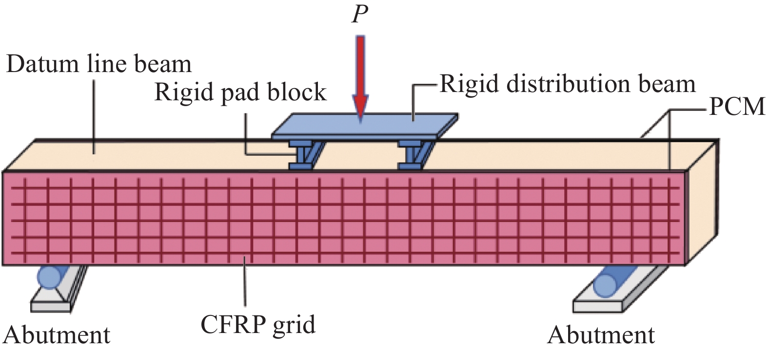
本试验为四点弯曲试验,均采用量程为500 kN的液压作动器,试件通过端支座进行简支约束,形成了2350 mm的净跨和1100 mm的剪跨。试验加载示意图如图2所示。在支座及加载点处布置8个线性位移计(LVDTs)来测量相应位置的竖向位移,在钢筋、混凝土、PCM和CFRP网格处布置电阻应变片来测量应变,具体布置位置如图3所示,其中C-1至C-6为试件表面应变片;D1至D8为位移传感器;S-1至S-7为BS和BGS试件的钢筋应变片。参考梁BS,出现弯曲裂缝之前,加载速率设定为4 kN/min;出现弯曲裂缝后,设定为6 kN/min;对于加固梁BG和BGS,全程以8 kN/min的速率恒定加载。在试验加载过程中,由人工观测裂缝的出现和发展,并进行相应的记录。
2. 有限元模型的建立
采用有限元软件ABAQUS对CFRP网格-PCM抗剪加固RC梁进行模拟分析。建立模型时,混凝土梁、CFRP网格和PCM均采用连续实体单元C3D8R单元,受力纵筋和箍筋采用桁架单元T3D2单元;CFRP网格-PCM加固层与混凝土之间的粘结行为采用双线性粘结滑移本构模型,粘聚单元的受力损伤行为通过引入牵引分离定律来表征,粘结层采用COH3D8单元;由于复合型裂纹常被视为I型裂纹,故采用内聚力模型(CZM)来模拟对界面的损伤;考虑到加载点位置可能产生明显的应力集中现象降低有限元计算的收敛性,故在支座和加载点位置分别布置一块刚性垫块,垫块采用S4R单元与试件表面之间采用绑定约束;由于PCM和混凝土都属于水泥基复合材料,受力性能相似[5, 16],故采用与混凝土相同的材料本构模型,其输入的参数[17]见表5;钢筋的受力性能采用强化模型来模拟;CFRP网格的本构关系由下式表达:
σf={εEf0<ε<εfu0ε>εfu (1) 式中:
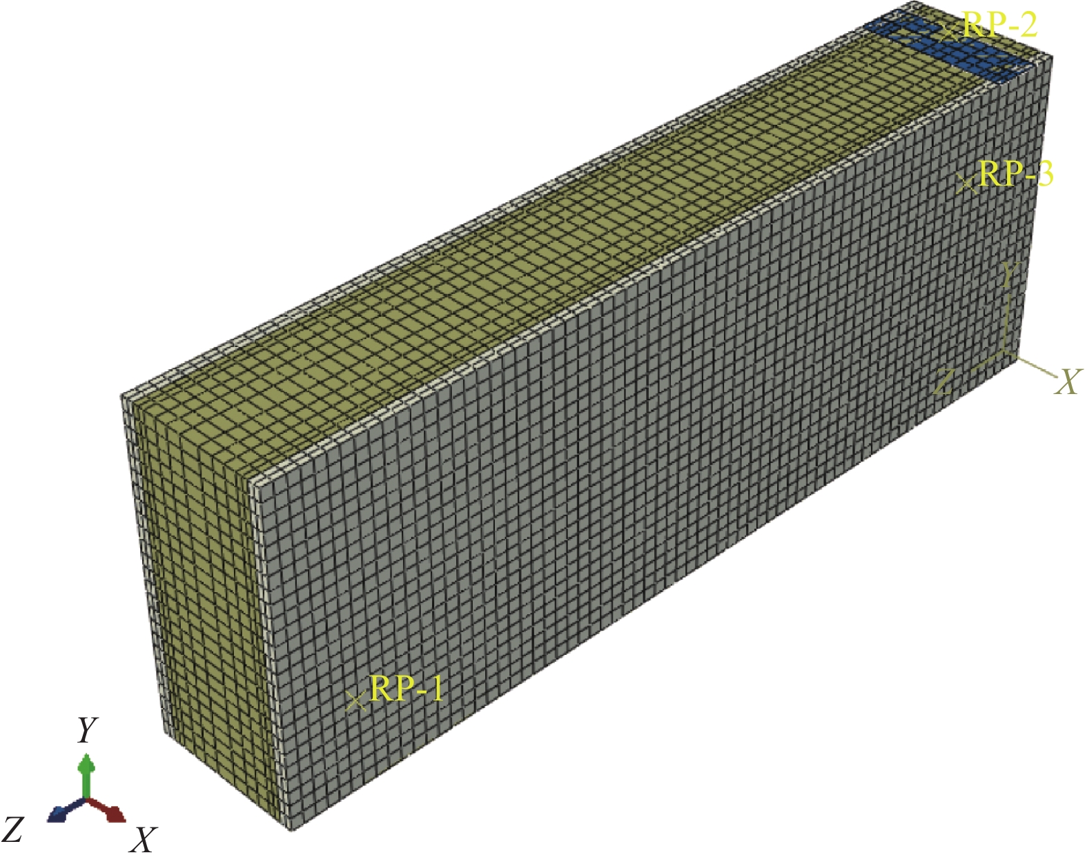
σ f为CFRP网格的应力;ε为CFRP网格发生的应变;εfu为CFRP网格的极限应变;Ef为CFRP网格的弹性模量。表 5 混凝土塑性损伤模型参数取值Table 5. Parameters of plastic damage model for concreteType Expansion angle ψ Offset ε σb0/σc0 Kc Coefficient of viscosity μ Value 38 0.1 1.16 0.6667 0.0005 Notes: σb0/σc0—Ratio of biaxial and uniaxial compression limit strength; Kc—Ratio of stretching and the second stress invariant on the compression meridian. 考虑到试件的对称性,采用1/2模型进行有限元模型的分析,并设定钢筋、CFRP网格筋和混凝土的单元网格尺寸为20 mm,靠近粘结层位置的混凝土和PCM单元网格尺寸为10 mm。在建模分析时,忽略钢筋与混凝土的相对滑移而采用嵌入约束来考虑二者之间的相互作用,来研究加固层与混凝土粘结界面的应力响应,加固试件和未加固试件的有限元模型如图4所示。
3. 试验结果及有限元模型验证
3.1 CFRP网格-PCM加固RC梁破坏形态
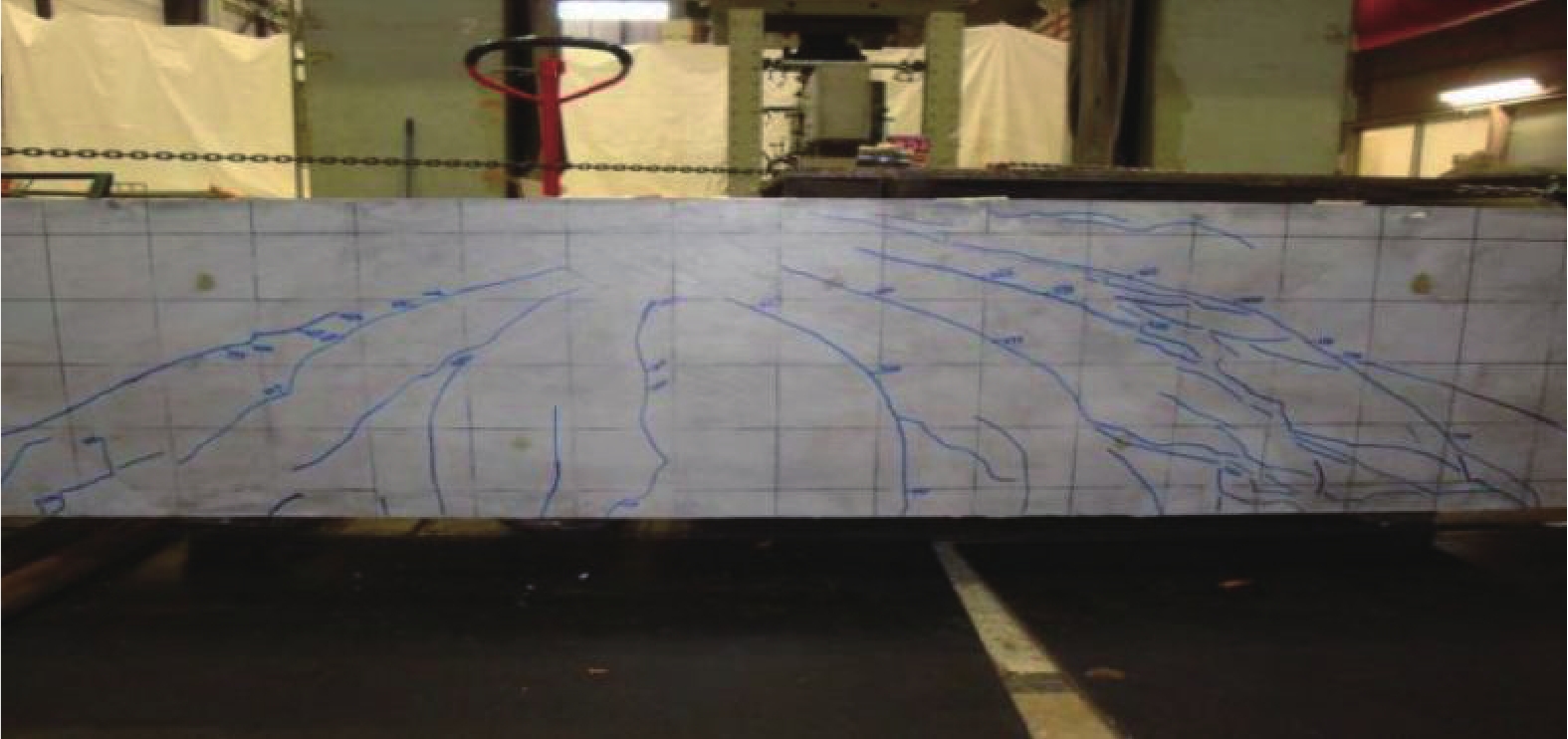
试验结果表明,3根试验梁均发生了剪切破坏,CFRP网格-PCM加固层未发生剥离破坏,图5为试验梁BGS发生剪切破坏的裂缝发展,图6为有限元模拟分析得到的梁受拉塑性损伤分布图与试验测得的梁表面裂缝形态分布对比情况。可以看出,有限元模拟结果与试验结果吻合较好。各试件的破坏过程类似,在加载初期,试件在跨中附近底部出现第一条竖向裂缝,并随着荷载的增加,裂缝逐渐向上和向两侧扩展;当加载至一定荷载时,在支座和加载点的连线区域附近出现若干条斜裂缝,并随着荷载的增大斜裂缝不断发展;当荷载增加至最大时,斜裂缝贯通试件整个截面而发生剪切破坏。
对比加固试件BG、BGS和不加固试件BS的裂缝形态可得出:在试件BS中裂缝带形态相较于加固试件更清晰、分散,且局部PCM出现剥离,而试件BGS和BS的裂纹复杂并出现多条微裂缝,这是由于加固试件侧面粘贴的CFRP网格限制了斜裂缝的发展,导致裂缝的扩展形态发生了变化。
3.2 CFRP网格-PCM加固RC梁荷载-位移曲线
各试件的试验结果见表6,荷载-位移曲线见图7。由表6和图7可知:当加载至P≈200 kN时,试件因出现弯曲裂缝,导致曲线斜率发生变化;当P>600 kN 时,加固试件BG和BGS的曲线斜率(刚度)大于参考试件BS,这表明CFRP网格-PCM加固方法能有效提高RC梁的抗弯刚度,另外,试件BGS中抗剪筋配筋率(0.35%)相较于试件BS(0.36%)更低,但是试件BGS在CFRP网格-PCM加固层的作用下获得了更高的刚度,可说明侧面粘贴CFRP网格-PCM加固层能有效地提高RC梁的弯曲刚度。且由图7可知,相较于试件BS,加固试件BG和BGS的剪切开裂荷载(Ps)比参考试件BS的更高,其中加固试件BGS获得了更大的极限荷载,可表明RC梁侧粘贴CFRP网格-PCM加固层不仅能够限制斜裂缝的发展,而且还能够提高RC梁的承载力。试验的试件荷载-位移曲线与有限元计算的荷载-跨中位移曲线形态基本相同,曲线吻合度较高。
3.3 CFRP网格-PCM加固RC梁荷载-应变曲线
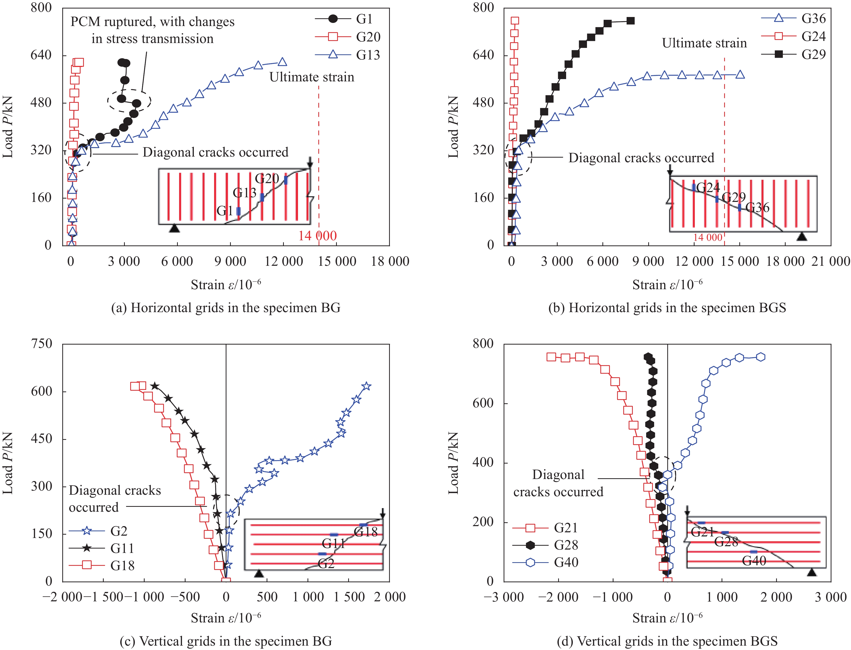
各试件在相同位置下的荷载-钢筋应变关系如图8所示,受拉钢筋始终处于线弹性变形阶段,其应变曲线基本表现为线性增长的趋势,在相同荷载水平(617 kN)下,参考试件BS的纵向受拉钢筋应变比加固试件BG和BGS更大,故CFRP网格分担了纵向受拉钢筋的应变;受压纵筋在加载初期,曲线表现为线性关系,当P≈600 kN时,其应变迅速增加,且试件BS的纵向受压钢筋在更低的荷载水平下屈服(试件BS和BGS中纵向受压钢筋分别在586 kN和689 kN时屈服),并在同一荷载水平下,试件BGS中受压钢筋的应变减小而提高了纵向受压钢筋在试件BGS中的屈服荷载,可说明CFRP网格具有与纵向受压钢筋相同的贡献;斜裂缝出现之后,箍筋应变开始呈不均匀增大分布,靠近临界斜裂缝的箍筋应变(如S3处的应变)相较于较远的箍筋应变更大(如S4处的应变),试件BS的箍筋应变增长速度比试件BGS更快,当荷载达到约500 kN时,试件BS的S3位置箍筋发生屈服,当荷载接近600 kN时,曲线斜率突增,拐点箍筋被拉断,试件发生破坏,可说明试件BGS中CFRP网格能够与箍筋共同承担剪力,导致箍筋的应变降低。
加固试件BG和BGS中CFRP网格的荷载-CFRP网格应变关系如图9所示。由图9(a)、9(b)可知,在剪切斜裂缝出现之前,横向网格筋的应变曲线近似一条竖线,网格筋应变基本为0,斜裂缝出现后,曲线出现拐点,网格筋应变快速增加,这表明横向CFRP网格筋与箍筋的作用机制相同。试件BG中横向网格筋最大应变(ε(G13)=11921×10−6)未达到网格极限应变(14000×10−6),故试件最终发生剪切破坏时,CFRP网格并未被充分利用,网格强度最大利用率为85%;而试件BGS在加载至约575 kN时,G36位置处横向网格筋应变急剧增加至ε(G36)=15000×10−6超过了网格极限应变,网格筋被拉断,而其他位置的网格应变继续增加,这表明应力在CFRP网格-PCM加固层中的不均匀分布,当某一位置的网格筋断裂后,会将应力传递至PCM或相邻的网格,使网格均匀受力。
表 6 CFRP网格-PCM加固RC梁试验结果汇总Table 6. Summary of test results for CFRP grid-PCM shear-reinforced RC beamsSpecimen Peak load P/kN
Pt/PcCross-mid deflection D/mm
Dt/DcShear cracking load Ps/kN
Pst/PscTest value
Pt/kNSimulation value
Pc/kNTest value
Dt/mmSimulation value
Dc/mmTest value
Pst/kNSimulation value
Psc/kNBS 690 614 1.12 8.35 8.07 1.03 210 172 1.22 BG 617 601 1.03 7.09 6.77 1.05 225 188 1.19 BGS 757 722 1.05 7.40 7.39 1.00 320 256 1.25 由图9(c)、9(d)可知,纵向网格筋的应变分布以梁的中性轴为界限,中性轴以上受压,中性轴以下受拉,这表明纵向CFRP网格筋的性能与纵向受力钢筋相似。当达到剪切开裂荷载后,位于中性轴以下的纵向网格应变明显增加,故在剪切斜裂缝出现后,纵向CFRP网格筋能够抑制斜裂缝的出现和扩展,发挥了一定的抗剪作用,但相比较横向CFRP网格筋的抗剪贡献较小。
4. CFRP网格的应变分析
4.1 CFRP网格的抗剪贡献
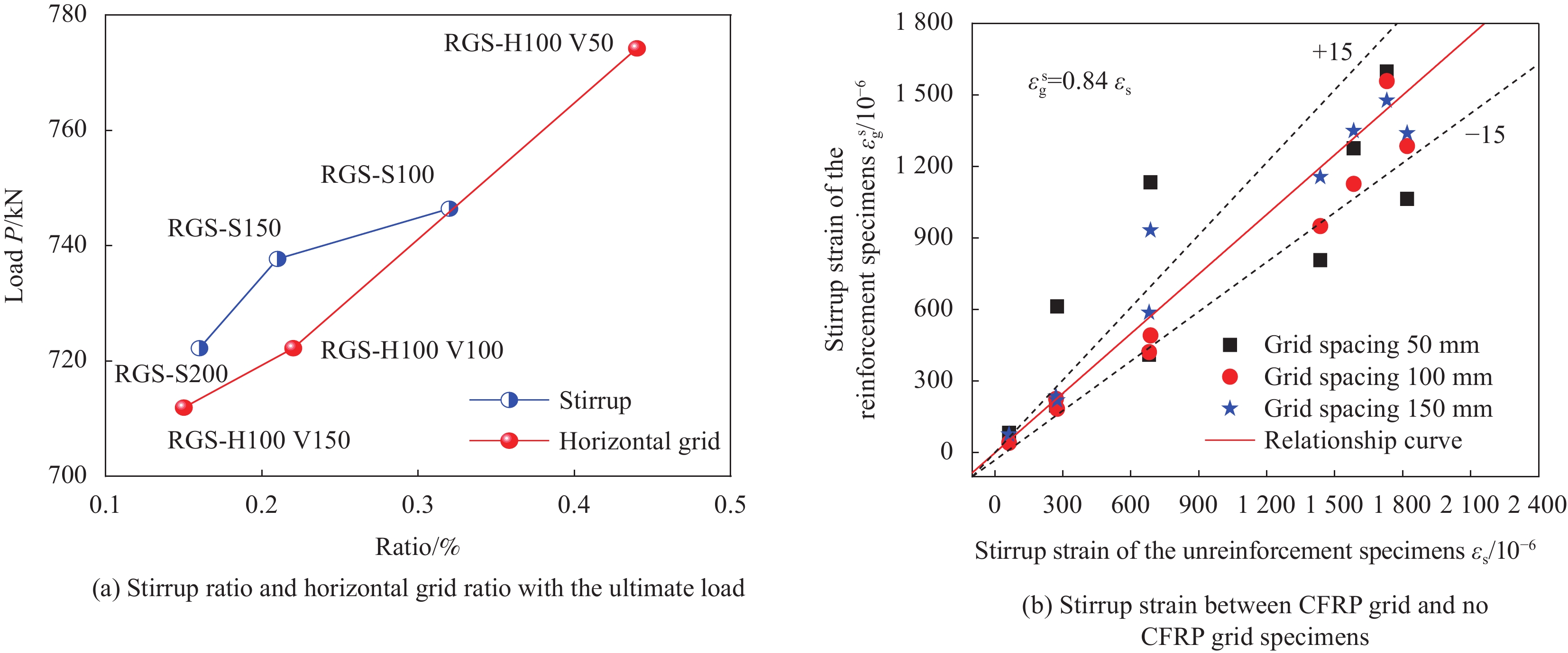
由前述分析可知,箍筋与横向CFRP网格筋能够相互分担彼此的应变,故以加固试件BGS为原型,将是否配置CFRP网格加固层作为变化参数建立3组试件模型(编号分别为NRS-50、RGS-50、NRS-100、RGS-100、NRS-150和RGS-150)及6个不同配筋量的加固RC梁试件模型(编号分别为RGS-S200、RGS-S150、RGS-S100、RGS-H100 V150、RGS-H100 V100和RGS-H100 V50)分别进行了有限元分析,具体参数信息分别见表7和表8。对比横向CFRP网格筋与箍筋配筋量和试件的极限荷载之间的关系曲线,如图10(a)所示。
表 7 RGS试件参数信息Table 7. Parameter information of RGS specimensSpecimen Stirrup Stirrup ratio
/%Grid type-spacing: Vertical and horizontal
/(mm×mm)Reinforcement ratio
/%Ultimate load
/kNRGS-S200 D6-SD345@200 0.16 CR8-100×100 0.22 722.2 RGS-S150 D6-SD345@150 0.21 737.7 RGS-S100 D6-SD345@100 0.32 746.4 RGS-H100 V150 D6-SD345@200 0.16 CR8-100×150 0.15 711.9 RGS-H100 V100 CR8-100×100 0.22 722.2 RGS-H100 V50 CR8-100×50 0.44 774.2 Notes: RGS—Reinforced concrete (RC) beam with stirrup and CFRP-PCM reinforcement layer; S200—Stirrup spacing is 200 mm; H—Horizontal grid spacing; V—Vertical grid spacing. 表 8 CFRP网格-PCM加固RC梁试件与未加固试件参数信息Table 8. Parameter information of CFRP grid-PCM shear-reinforced RC beam specimens and unreinforced specimensType of specimen Specimen number Vertical reinforcement Stirrup CFRP grid PCM thickness
/mmHorizontal grid ratio/% Tensile reinforcement Compressive reinforcement First group NRS-50 6-D32-SD345 2-D10-SD345 D6-SD345@200 — — — RGS-50 CR8@50 20 0.44 Second group NRS-100 — — — RGS-100 CR8@100 20 0.22 Third group NRS-150 — — — RGS-150 CR8@150 20 0.15 Notes: NRS-50—Reinforced concrete (RC) beam with no CFRP-PCM reinforcement layer but with stirrup in 50 mm spacing (NRS-100 and NRS-150 are in the same manner); RGS-50—Reinforced concrete (RC) beam with CFRP-PCM reinforcement layer and stirrup in 50 mm spacing (RGS-100 and RGS-150 are in the same manner). 由表7和图10(a)可知:CFRP网格-PCM加固RC梁的抗剪承载力随着配筋率的增加呈非线性增加趋势,并随着两种抗剪加强材料的配比变化而变化,当配筋率超过约0.33%后,横向CFRP网格相较于箍筋对RC梁的抗剪承载力提高更加显著,这表明横向CFRP网格筋分担了更多的箍筋应变导致箍筋的强度利用率明显降低。
加固试件与未加固试件中27个相同位置的箍筋应变分布见图10(b),具体参数信息见表8。通过对两类试件中相同位置的箍筋应变回归分析发现,加固试件中箍筋应变基本等于未加固试件中箍筋应变的0.84倍,初步说明在CFRP网格-PCM抗剪加固RC梁中,CFRP网格分担了16%的箍筋应变,降低了箍筋的应力水平。
4.2 CFRP网格的有效应变
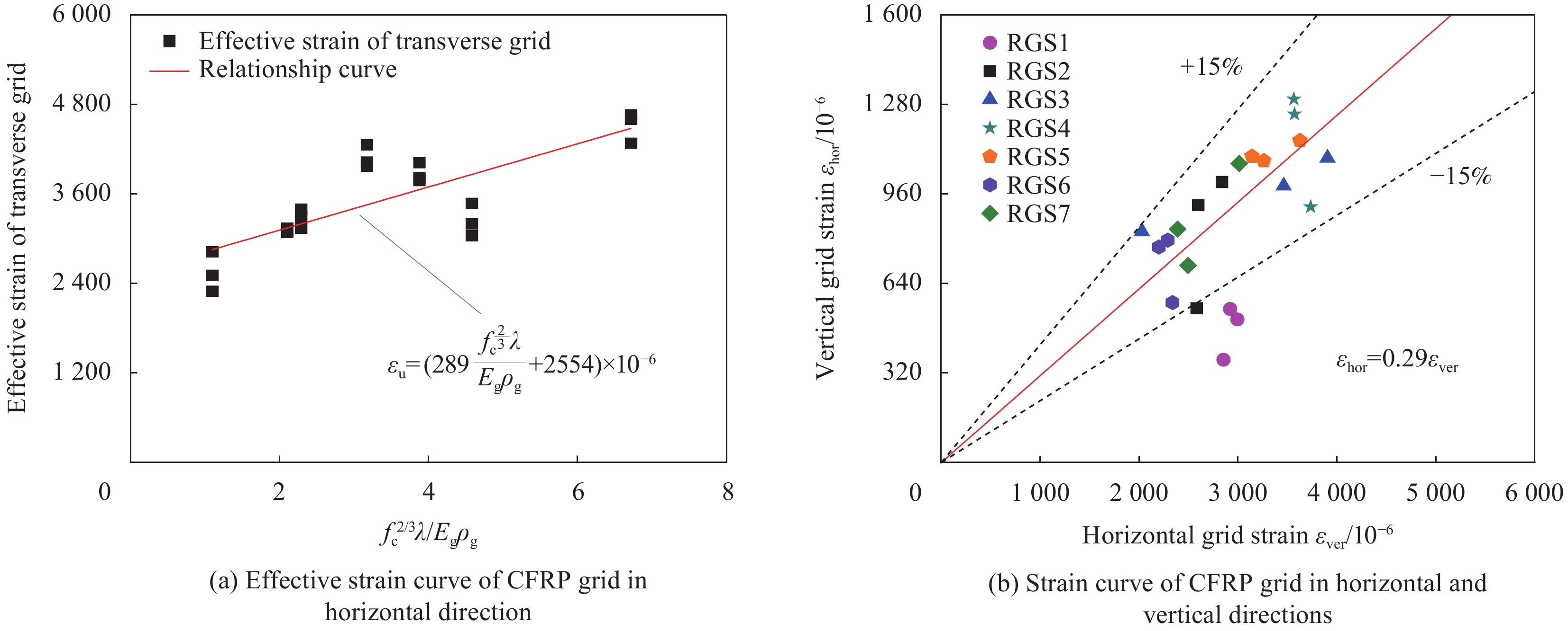
以BGS为原型建立的7个CFRP网格-PCM抗剪加固RC梁试件模型的有效应变见表9,其中变化参数为剪跨比λ、混凝土抗压强度fc和CFRP网格配筋率ρg,并引入FRP网格的弹性模量Eg统一量纲,对21个横向CFRP网格筋应变数据进行回归分析得到的纵横向CFRP网格筋应变的关系曲线见图11。由表9、图11可知:横向CFRP网格的有效应变与剪跨比λ、混凝土抗压强度fc和CFRP网格配筋率ρg和CFRP网格的弹性模量Eg的组合值呈线性正相关关系,且纵向CFRP网格筋的应变与横向CFRP网格筋之间呈比例为0.29倍的线性关系,二者的相关系数达到0.97,误差小于±15%。根据有效应变理论[7],FRP网格的抗剪贡献取决于FRP网格筋的有效应变 εu,即考虑FRP网格产生的真实应变,因此,横纵向FRP网格筋的有效应变 εver 和 εhor 之间的关系为
表 9 纵向和横向CFRP网格应变信息汇总Table 9. Summary of grid strain information for horizontal and vertical CFRPSpecimen Shear
span λConcrete strength/MPa CFRP grid
typeRatio ρg/% PCM thickness/ mm Vertical grid strain
εver/10−6Horizontal grid strain
εhor/10−6Tensile
strength ftCompression strength
fcRGS1 2.6 2.92 34.1 CR8@50 0.44 20 2853.17 367.52 2993.50 511.91 2919.94 548.94 RGS2 2.6 2.92 34.1 CR8@100 0.22 2581.23 551.82 2837.57 1003.05 2599.29 920.19 RGS3 2.6 2.92 34.1 CR8@150 0.15 2029.87 825.87 3905.37 1088.63 3461.74 988.99 RGS4 1.8 2.92 34.1 CR8@100 0.22 3735.11 913.96 3564.48 1299.26 3570.80 1245.58 RGS5 2.2 2.92 34.1 CR8@100 0.22 3625.54 1150.78 3141.04 1094.90 3260.70 1078.79 RGS6 2.6 2.20 26.6 CR8@100 0.22 2337.90 571.62 2200.77 770.38 2289.55 794.90 RGS7 2.6 2.64 38.0 CR8@100 0.22 2494.30 704.24 3012.34 1069.08 2389.03 834.12 εu=(289f23cλEgρg+2554)×10−6 (2) εhor=0.29εver (3) 5. CFRP网格-PCM抗剪加固RC梁的承载力计算方法
5.1 改进的桁架拱模型
在CFRP网格-PCM抗剪加固RC梁中,纵向CFRP网格的销栓作用能够有效地传递剪力并限制剪切斜裂缝的发展,对加固RC梁的受剪性能具有较大的影响,故不应该忽略纵向CFRP网格的抗剪作用;另外,CFRP网格与钢筋之间的相互作用导致横向CFRP网格分担了16%的箍筋应变,降低了箍筋的抗剪作用,故在评估箍筋的抗剪贡献时应对其折减16%。综合考虑上述问题后,本文提出一种改进的桁架拱模型来揭示CFRP网格-PCM抗剪加固RC梁的受剪机制:由受压拱体(临界斜裂缝上部的混凝土和PCM)、斜向受压腹杆(斜裂缝间的混凝土和PCM)、竖向受拉腹杆(箍筋和横向CFRP网格)和下弦拉杆(纵向受拉钢筋和纵向CFRP网格)组成,如图12所示。
5.2 CFRP网格-PCM加固RC梁承载力计算
根据本文提出的改进的桁架拱模型,通过叠加CFRP网格-PCM抗剪加固RC梁中各组分材料的抗剪贡献可确定加固RC梁的抗剪承载力[18-19],CFRP网格的抗剪贡献来自横向CFRP网格筋和纵向CFRP网格筋,计算公式如下:
V=Vc+Vp+Vs+Vg (4) 式中:Vc和Vs分别为混凝土和箍筋的抗剪贡献;Vp和Vg分别为PCM和CFRP网格的抗剪贡献。PCM抗剪贡献采用与混凝土相同的计算方法,即
Vc(Vp)=αcvftbd (5) 采用我国现行规范中箍筋抗剪贡献的计算公式时,根据CFRP网格分担的16%的箍筋应变,引入一个0.84的折减系数,以此来考虑CFRP网格对箍筋影响:
Vs=0.84fyvAsvsd (6) 式中:
αcv 为混凝土受剪承载力系数,取1.75/(λ+1) ;ft 为混凝土或PCM的抗拉强度;fyv 为箍筋的屈服强度;Asv 为间距s范围内箍筋各肢的全部截面面积;b为RC梁宽或PCM的厚度;s为箍筋间距;d为试件有效高度;λ为试件的剪跨比,取剪跨长度与有效高度之比。ACI 440.2 R-08[20]基于有效应变理论给出了FRP材料的抗剪贡献为
Vg=Agffe(sinβ+cosβ)dsg (7) 式中:Ag为间距sg范围内FRP网格筋各肢的全部横截面面积;sg为FRP网格的间距;β为FRP网格与梁纵向轴线之间的夹角;ffe为横向FRP网格的有效应力,ffe=εfeEg,Eg为FRP网格的弹性模量,εfe为FRP网格的有效应变,即
εfe, ver =(289f23cλEgρg+2554)×10−6 (8) 纵向FRP网格的抗剪贡献及纵横向FRP网格应变之间存在呈比例为0.29的线性关系,FRP网格的抗剪贡献计算表达式如下:
εfe,hor=kεfe,ver=0.29×(289f23cλEgρg+2554)×10−6 (9) Vg=EgAg[εfe,ver(sinβver+cosβver)+εfe,hor(sinβhor+cosβhor)]sgd (10) 式中:k为纵横向FRP网格的应变比较系数,k=0.29;εfe,ver和εfe,hor分别为横向和纵向FRP网格筋的有效应变;βver和βhor分别为横向和纵向FRP网格筋与试件纵向轴线之间的夹角。
为了验证提出的CFRP网格-PCM抗剪加固RC梁承载力计算方法的有效性和适用性,搜集了21个既有的FRP网格抗剪加固RC梁的试验数据[5, 10-12, 21-25],并与既有具有代表性的研究文献[5]给出的计算方法进行了比较分析,如表10、图13所示。基于改进的桁架拱模型和考虑纵横向CFRP网格筋有效应变提出的CFRP网格-PCM抗剪加固RC梁的承载力计算方法相较于既有的计算方法具有更好的适用性和准确性,能够满足设计要求。同时,可以看出计算结果仍存在一定的离散性,分析认为主要是由于将纵横向网格筋作为刚性节点考虑引起的,后续将建立可模拟格点真实受力状态的精细化有限元模型进一步深入研究。
表 10 不同FRP网格抗剪加固RC梁抗剪承载力计算值与试验值比较Table 10. Comparison of calculated and experimental values of shear capacity of RCbeams strengthened with different FRP gridsData
sourcesSpecimen Pexp/kN Pcal[5]/kN Pcal/kN Pexp/Pcal[5] Pexp/Pcal Pexp/Pcal analysis Pexp/Pcal[5] analysis Mean
valueVariable
coefficientMean
valueVariable
coefficientText BG 617 330 466 1.87 1.32 1.22 0.16 1.85 0.32 BGS 757 414 562 1.83 1.35
[5]RCF4 881 768 625 1.15 1.41 RCF6 949 887 704 1.07 1.35 RCF8 943 939 769 1.00 1.23 RCF4’ 950 810 721 1.17 1.32 RCF64 860 823 704 1.04 1.22
[6]PGB 352 105 290 3.35 1.21
[11]S150-CGM 677 449 458 1.51 1.48 S250-CGM 571 248 428 2.30 1.33
[12]L3 373 186 385 2.00 0.97 L4 511 253 385 2.01 1.33
[21]NO.2 588 320 408 1.84 1.44 NO.4 631 332 498 1.90 1.27
[22]SB1 376 245 304 1.53 1.24 SB2 449 230 446 1.95 1.01 SB3 471 190 601 2.48 0.78
[23]SB2-3 449 229 441 1.96 1.02
[24]D 195 122 255 1.60 0.76
[25]C35 S3-M2-G2 674 261 472 2.58 1.43 C40 S0-M2-G2 bc 484 181 395 2.67 1.22 Notes: Pcal—Shear bearing capacity of the FRP grid reinforced RC beam which is calculated based on the proposed method; Pexp—Shear bearing capacity of the FRP grid reinforced RC beam which is calculated based on the corresponding test; RCF4, RCF6 and RCF8—Reinforced by CR4 CFRP, CR6 CFRP and CR8 CFRP grid whose vertical reinforcement interval was 50 mm compared with 150 mm of other specimens (CR4, CR6 and CR8 are the type of the CFRP grid in ABAQUS); RCF4'—Reinforced by CR4 CFRP grid whose vertical reinforcement interval was 50 mm compared with 50 mm of other specimens; RCF64—Reinforced by CR6&4 CFRP grid whose horizontal grid was CR4 and vertical grid was CR6; PGB—Beam was strengthened with high strength PCM and high strength carbon fiber-reinforced plastics (CFRP) gride bars; S150-CGM and S250-CGM—Beam with CFRP grid embedded in mortar (CGM), and the beam with 6 mm stirrups @150 mm c/c and @250 mm c/c; L3—Fiber grid and polymer mortar reinforced concrete beams (FRP GRID&NC-RC); L4—Fiber grid and engineered cementitous composite (ECC) reinforced concrete beams (FRP GRID&ECC-RC); NO.2 and NO.4—Beam with 2 row and 4 row of CFRP grid; SB1, SB2, SB3—FRP grid used in the ultra high toughness cementitious composite (UHTCC) layer (Measured thickness: 1 mm, 3 mm and 5 mm respectively); SB2-3—A 3 mm BFRP grid reinforced ECC composite SB2 reinforced concrete beam; D—RC beam strengthened with FRP grid; C35 S3-M2-G2—Beam C35 S3 with stirrup was strengthed by the use of mortar 2 and grid M; C40 S0-M2-G2 bc—Beam C40 S0 without stirrup but was strengthed by the use of mortar 2 and grid M; c/c—Center/Center; BFRP—Boron fiber reinforced plastic. 6. 结 论
(1) 采用实体单元模拟碳纤维增强树脂复合材料(Carbon fiber reinforced polymer,CFRP)网格来考虑其在加固钢筋混凝土(RC)梁中真实的受力行为,界面粘聚单元来模拟CFRP网格-聚合物水泥砂浆(Polymer cement mortar,PCM)加固层与混凝土间的粘结界面可建立具有高精确度和高计算效率的CFRP网格-PCM抗剪加固RC梁的有限元分析模型。
(2) RC梁侧粘贴CFRP网格-PCM加固层不仅能够限制斜裂缝的发展,而且还提高了RC梁的抗剪承载力。
(3) CFRP网格与钢筋之间具有良好的协同工作性能。其中,应当考虑纵向CFRP网格筋的影响,横向CFRP网格筋分担了约16%的箍筋应变,并且通过回归分析得出了纵向CFRP网格筋的应变与横向CFRP网格筋之间呈0.29倍的线性关系。
(4) 通过综合考虑纵向CFRP网格的销栓作用和横向CFRP网格分担的箍筋应变,提出了基于改进的桁架-拱模型的承载力计算方法,其计算值与试验值具有较高的吻合度,能够满足设计要求。
-
表 1 试件设计
Table 1 Specimen design
Specimen Existing steel bars FRP grid Shear
span λPCM thickness/
mmExisting vertical reinforcement ratio/% Anti-shear reinforcement ratio/% Tensile reinforcement Handling reinforcement Stirrup BS D32-SD345 D10-SD345 D10-SD345@200 — 2.63 — 5.8 0.36 BG D32-SD345 — — CR8-100×100 20 5.6 0.22 BGS D32-SD345 D10-SD345 D6-SD345@200 CR8-100×100 20 5.8 0.35 Notes: B—Reinforced concrete beam; S—Beam is equipped with stirrup; G—Stick carbon fiber reinforced polymer (CFRP) grid-polymer cement mortar (PCM) reinforcement layer on both sides; BS—Reinforced concrete beams provided with stirrups; BG—Reinforced concrete beam with only CFRP-PCM reinforced layer without stirrup; BGS—Reinforced concrete beams with stirrups and CFRP-PCM reinforcement layer; D—Diameter; SD—Reinforcement strength grade; CR8—CFRP grid of 8 mm in diameter; FRP—Fiber reinforced polymer. 表 2 混凝土配合比
Table 2 Concrete mix proportion
Maximum
grain size/mmColony/
mmWater cement
ratio/%Air ratio/% Measurement unit/(kg·m–3) Water Cement Fine aggregate Coarse aggregate Admixture 20 120 55.6 4.5 158 284 792 1126 1.3 表 3 混凝土和聚合物水泥砂浆(PCM)材料性能
Table 3 Properties of concrete and polymer cement mortar (PCM) materials
Material Compression strength/MPa Tensile strength/MPa Modulus of elasticity/GPa Concrete 34.1 2.92 31.9 PCM 36.7 2.87 30.1 表 4 钢筋与碳纤维增强树脂复合材料(CFRP)网格的力学性能
Table 4 Mechanical properties of steel and carbon fiber reinforced polymer (CFRP) grids
Material Type Cross-sectional area/mm2 Yield strength
/MPaModulus of elasticity/GPa Tensile strength
/MPaConcrete iron D32 794.2 389 200 587 D10 71.3 413 200 561 D6 31.7 417 200 570 CFRP grid CR8 26.4 — 100 1400 表 5 混凝土塑性损伤模型参数取值
Table 5 Parameters of plastic damage model for concrete
Type Expansion angle ψ Offset ε σb0/σc0 Kc Coefficient of viscosity μ Value 38 0.1 1.16 0.6667 0.0005 Notes: σb0/σc0—Ratio of biaxial and uniaxial compression limit strength; Kc—Ratio of stretching and the second stress invariant on the compression meridian. 表 6 CFRP网格-PCM加固RC梁试验结果汇总
Table 6 Summary of test results for CFRP grid-PCM shear-reinforced RC beams
Specimen Peak load P/kN
Pt/PcCross-mid deflection D/mm
Dt/DcShear cracking load Ps/kN
Pst/PscTest value
Pt/kNSimulation value
Pc/kNTest value
Dt/mmSimulation value
Dc/mmTest value
Pst/kNSimulation value
Psc/kNBS 690 614 1.12 8.35 8.07 1.03 210 172 1.22 BG 617 601 1.03 7.09 6.77 1.05 225 188 1.19 BGS 757 722 1.05 7.40 7.39 1.00 320 256 1.25 表 7 RGS试件参数信息
Table 7 Parameter information of RGS specimens
Specimen Stirrup Stirrup ratio
/%Grid type-spacing: Vertical and horizontal
/(mm×mm)Reinforcement ratio
/%Ultimate load
/kNRGS-S200 D6-SD345@200 0.16 CR8-100×100 0.22 722.2 RGS-S150 D6-SD345@150 0.21 737.7 RGS-S100 D6-SD345@100 0.32 746.4 RGS-H100 V150 D6-SD345@200 0.16 CR8-100×150 0.15 711.9 RGS-H100 V100 CR8-100×100 0.22 722.2 RGS-H100 V50 CR8-100×50 0.44 774.2 Notes: RGS—Reinforced concrete (RC) beam with stirrup and CFRP-PCM reinforcement layer; S200—Stirrup spacing is 200 mm; H—Horizontal grid spacing; V—Vertical grid spacing. 表 8 CFRP网格-PCM加固RC梁试件与未加固试件参数信息
Table 8 Parameter information of CFRP grid-PCM shear-reinforced RC beam specimens and unreinforced specimens
Type of specimen Specimen number Vertical reinforcement Stirrup CFRP grid PCM thickness
/mmHorizontal grid ratio/% Tensile reinforcement Compressive reinforcement First group NRS-50 6-D32-SD345 2-D10-SD345 D6-SD345@200 — — — RGS-50 CR8@50 20 0.44 Second group NRS-100 — — — RGS-100 CR8@100 20 0.22 Third group NRS-150 — — — RGS-150 CR8@150 20 0.15 Notes: NRS-50—Reinforced concrete (RC) beam with no CFRP-PCM reinforcement layer but with stirrup in 50 mm spacing (NRS-100 and NRS-150 are in the same manner); RGS-50—Reinforced concrete (RC) beam with CFRP-PCM reinforcement layer and stirrup in 50 mm spacing (RGS-100 and RGS-150 are in the same manner). 表 9 纵向和横向CFRP网格应变信息汇总
Table 9 Summary of grid strain information for horizontal and vertical CFRP
Specimen Shear
span λConcrete strength/MPa CFRP grid
typeRatio ρg/% PCM thickness/ mm Vertical grid strain
εver/10−6Horizontal grid strain
εhor/10−6Tensile
strength ftCompression strength
fcRGS1 2.6 2.92 34.1 CR8@50 0.44 20 2853.17 367.52 2993.50 511.91 2919.94 548.94 RGS2 2.6 2.92 34.1 CR8@100 0.22 2581.23 551.82 2837.57 1003.05 2599.29 920.19 RGS3 2.6 2.92 34.1 CR8@150 0.15 2029.87 825.87 3905.37 1088.63 3461.74 988.99 RGS4 1.8 2.92 34.1 CR8@100 0.22 3735.11 913.96 3564.48 1299.26 3570.80 1245.58 RGS5 2.2 2.92 34.1 CR8@100 0.22 3625.54 1150.78 3141.04 1094.90 3260.70 1078.79 RGS6 2.6 2.20 26.6 CR8@100 0.22 2337.90 571.62 2200.77 770.38 2289.55 794.90 RGS7 2.6 2.64 38.0 CR8@100 0.22 2494.30 704.24 3012.34 1069.08 2389.03 834.12 表 10 不同FRP网格抗剪加固RC梁抗剪承载力计算值与试验值比较
Table 10 Comparison of calculated and experimental values of shear capacity of RCbeams strengthened with different FRP grids
Data
sourcesSpecimen Pexp/kN Pcal[5]/kN Pcal/kN Pexp/Pcal[5] Pexp/Pcal Pexp/Pcal analysis Pexp/Pcal[5] analysis Mean
valueVariable
coefficientMean
valueVariable
coefficientText BG 617 330 466 1.87 1.32 1.22 0.16 1.85 0.32 BGS 757 414 562 1.83 1.35
[5]RCF4 881 768 625 1.15 1.41 RCF6 949 887 704 1.07 1.35 RCF8 943 939 769 1.00 1.23 RCF4’ 950 810 721 1.17 1.32 RCF64 860 823 704 1.04 1.22
[6]PGB 352 105 290 3.35 1.21
[11]S150-CGM 677 449 458 1.51 1.48 S250-CGM 571 248 428 2.30 1.33
[12]L3 373 186 385 2.00 0.97 L4 511 253 385 2.01 1.33
[21]NO.2 588 320 408 1.84 1.44 NO.4 631 332 498 1.90 1.27
[22]SB1 376 245 304 1.53 1.24 SB2 449 230 446 1.95 1.01 SB3 471 190 601 2.48 0.78
[23]SB2-3 449 229 441 1.96 1.02
[24]D 195 122 255 1.60 0.76
[25]C35 S3-M2-G2 674 261 472 2.58 1.43 C40 S0-M2-G2 bc 484 181 395 2.67 1.22 Notes: Pcal—Shear bearing capacity of the FRP grid reinforced RC beam which is calculated based on the proposed method; Pexp—Shear bearing capacity of the FRP grid reinforced RC beam which is calculated based on the corresponding test; RCF4, RCF6 and RCF8—Reinforced by CR4 CFRP, CR6 CFRP and CR8 CFRP grid whose vertical reinforcement interval was 50 mm compared with 150 mm of other specimens (CR4, CR6 and CR8 are the type of the CFRP grid in ABAQUS); RCF4'—Reinforced by CR4 CFRP grid whose vertical reinforcement interval was 50 mm compared with 50 mm of other specimens; RCF64—Reinforced by CR6&4 CFRP grid whose horizontal grid was CR4 and vertical grid was CR6; PGB—Beam was strengthened with high strength PCM and high strength carbon fiber-reinforced plastics (CFRP) gride bars; S150-CGM and S250-CGM—Beam with CFRP grid embedded in mortar (CGM), and the beam with 6 mm stirrups @150 mm c/c and @250 mm c/c; L3—Fiber grid and polymer mortar reinforced concrete beams (FRP GRID&NC-RC); L4—Fiber grid and engineered cementitous composite (ECC) reinforced concrete beams (FRP GRID&ECC-RC); NO.2 and NO.4—Beam with 2 row and 4 row of CFRP grid; SB1, SB2, SB3—FRP grid used in the ultra high toughness cementitious composite (UHTCC) layer (Measured thickness: 1 mm, 3 mm and 5 mm respectively); SB2-3—A 3 mm BFRP grid reinforced ECC composite SB2 reinforced concrete beam; D—RC beam strengthened with FRP grid; C35 S3-M2-G2—Beam C35 S3 with stirrup was strengthed by the use of mortar 2 and grid M; C40 S0-M2-G2 bc—Beam C40 S0 without stirrup but was strengthed by the use of mortar 2 and grid M; c/c—Center/Center; BFRP—Boron fiber reinforced plastic. -
[1] 袁廷朋, 陆洲导, 张鑫. 钢筋混凝土结构受氯离子严重腐蚀后的加固处理[J]. 四川建筑科学研究, 2007, 33(1):98-99. DOI: 10.3969/j.issn.1008-1933.2007.01.028 YUAN Tingpeng, LU Zhoudao, ZHANG Xin. Reinforcement of reinforced concrete structure after severe corrosion by chloride ion[J]. Architectural Science Research in Sichuan,2007,33(1):98-99(in Chinese). DOI: 10.3969/j.issn.1008-1933.2007.01.028
[2] WANG B U, JI K, WU T, et al. Experimental investigation of stress transfer and failure mechanism between existing concrete and CFRP grid-sprayed PCM[J]. Construction and Building Materials,2019,215:43-58. DOI: 10.1016/j.conbuildmat.2019.04.168
[3] WANG B, WANG Z, UJI K. Experimental verification of a novel anchorage method of CFRP grid in mortar[J]. Structures,2020,28:1646-1660. DOI: 10.1016/j.istruc.2020.09.044
[4] 江佳斐, 隋凯. 纤维网格增强超高韧性水泥复合材料加固混凝土圆柱受压性能试验[J]. 复合材料学报, 2019, 36(8):1957-1967. JIANG Jiafei, SUI Kai. Experimental study of compression performance of concrete cylinder strengthened by textile reinforced engineering cement composites[J]. Acta Materiae Compositae Sinica,2019,36(8):1957-1967(in Chinese).
[5] GUO R, PAN Y, CAI L H, et al. Study on design formula of shear capacity of RC beams reinforced by CFRP grid with PCM shotcrete method[J]. Engineering Structures,2018,166:427-440. DOI: 10.1016/j.engstruct.2018.03.095
[6] AMIRUDDIN A A. Shear behavior of concrete beams strengthened with CFRP grid and PCM shotcrete[J]. EPI International Journal of Engineering,2019,2(1):5-8. DOI: 10.25042/epi-ije.022019.02
[7] KHALIFA A. Rehabilitation of rectangular simply supported RC beams with shear deficiencies using CFRP composites[J]. Construction and Building Materials,2002,16(2):135-146.
[8] 曹亮, 张海燕, 吴波. 纤维编织网增强低聚物砂浆加固钢筋混凝土梁受剪性能研究[J]. 工程力学, 2019, 36(1):207-215. DOI: 10.6052/j.issn.1000-4750.2017.11.0881 CAO Liang, ZHANG Haiyan, WU Bo. Shear performance research on reinforced concrete beams strengthened with the fiber woven mesh and oligomic mortar[J]. Engineering Mechanics,2019,36(1):207-215(in Chinese). DOI: 10.6052/j.issn.1000-4750.2017.11.0881
[9] 中国工程建设标准化协会. 碳纤维片材加固混凝土结构技术规程: CECS 146—2003[S]. 北京: 中国计划出版社, 2007. China Engineering Construction Standardization Association. Standardization of engineering construction: CECS 146—2003[S]. Beijing: China Planning Press, 2007(in Chinese).
[10] 郑宇宙. FRP格栅增强ECC复合加固混凝土梁试验与计算方法研究[D]. 南京: 东南大学, 2018. ZHENG Yuzhou. Experiment and calculation method research on reinforced concrete (RC) beams strengthened with the composite of FRP grid and ECC[D]. Nanjing: Southeast China University, 2018(in Chinese).
[11] AZAM R, SOUDKI K, WEST J S, et al. Strengthening of shear-critical RC beams: Alternatives to externally bonded CFRP sheets[J]. Construction and Building Materials,2017,151:494-503. DOI: 10.1016/j.conbuildmat.2017.06.106
[12] 陈文永, 陈小兵, 丁一, 等. 纤维网格及ECC材料抗剪加固性能研究[J]. 工业建筑, 2009, 39(12):118-122. CHEN Wenyong, CHEN Xiaobing, DING Yi, et al. The shear behavior of concrete beam reinforced with ECC and FRP grid[J]. Industrial Architecture,2009,39(12):118-122(in Chinese).
[13] GUO R, CAI L H, HINO S, et al. Experimental study on shear strengthening of RC beams with FRP grid-PCM reinforcement layer[J]. Applied Sciences,2019,9(15):1-21. DOI: 10.3390/app9152984
[14] Concrete Committee of Civil Engineering Society. Civil engineering society concrete standard square document[S]. Japan: Japan Civil Engineering Society, 2007(in Chinese).
[15] NAKAMURA S, YAMAGUCHI K, ARWINM A. Bending reinforcing effect of RC beams using a two-layer contact placed CFRP grid by PCM spraying method[J]. Proceeding of the Japan Concrete Institute,2009,131(2):1429-1434.
[16] MIYANO N, YAMAGUCHI K, TANIGUCHI K. Shear capacity for RC beam retrofitted by CFRP covering PCM shotcrete[J]. Proceedings of the Japan Concrete Institute,2013,35(2):1423-1428.
[17] 刘巍, 徐明, 陈忠范. ABAQUS混凝土损伤塑性模型参数标定及验证[J]. 工业建筑, 2014, 44(S1):167-171, 213. LIU Wei, XU Ming, CHEN Zhongfan. Parameters calibration and verification of concrete damage plasticity model of ABAQUS[J]. Industrial Architecture,2014,44(S1):167-171, 213(in Chinese).
[18] Japan Road Association. Specifications for highway bridges, Part V seismic design[S]. Tokyo: Japan Road Association, 2002.
[19] 国家标准抗震规范管理组. 建筑抗震设计规范: GB/T 50011—2010[S]. 北京: 中国建筑工业出版社, 2016. National Standard Seismic Code Management Group. Code for the seismic design of buildings: GB/T 50011—2010[S]. Beijing: China State Construction Industry Press, 2016(in Chinese).
[20] American Concrete Institute. Guide for the design and construction of externally bonded FRP systems for strengthening concrete structures: ACI 440.2 R-08[S]. Farmington Hills: American Concrete Institute, 2008.
[21] LIANG J, UJI K, MATSUMURA S, et al. Shear strengthening of RC beam with CFRP grid and sprayed mortar[J]. Proceeding of the Japan Concrete Institute,2008,30(2):607-612.
[22] 郑宇宙, 王文炜, 戴建国, 等. FRP-UHTCC复合层抗剪增强钢筋混凝土梁受力性能试验研究[J]. 建筑结构学报, 2019(8): 118-126. ZHENG Yuzhou, WANG Wenwei, DAI Jianguo, et al. Experimental study on mechanical performance of reinforced concrete beams shear-strengthened with FRP-UHTCC composite[J]. Journal of Architectural Structures, 2019(8): 118-126(in Chinese).
[23] 王文炜, 郑宇宙. BFRP格栅增强ECC加固钢筋混凝土梁抗剪承载力试验研究[C]//第九届全国建设工程FRP应用学术交流会. 重庆: 中国土木工程学会FRP及工程应用专业委员会, 2015: 326-331. WANG Wenwei, ZHENG Yuzhou. Experimental research on shear capacity of concrete beams strengthened with BFRP grid reinforced ECC[C]//The 9th National Construction Engineering FRP Application Academic Exchange Conference. Chongqing: FRP and Engineering Application Professional Committee of the Chinese Society of Civil Engineering, 2015: 326-331(in Chinese).
[24] LU Z D, YANG X, DAI J G . Shear behavior of RC beams strengthened with FRP grid reinforced engineered cementitious composites[C]//The Sixth Asia-Pacific Conference on FRP in Structures (APFIS2017). Singapore: International Institute for FRP in Construction (IIFC), 2017: 1-5.
[25] BLANKSVARD T, TALJSTEN B, CAROLIN A. Shear strengthening of concrete structures with the use of mineral-based composites[J]. Journal of Composites for Construction,2009,13(1):25-34. DOI: 10.1061/(ASCE)1090-0268(2009)13:1(25)
-
期刊类型引用(1)
1. 谈峰玲,吕淼,周浩,汪毅. 钢纤维增强聚合物水泥砂浆性能研究. 混凝土与水泥制品. 2024(06): 68-71 .  百度学术
百度学术
其他类型引用(0)
-


 下载:
下载:
