

Interfacial debonding failure of CFRP-strengthened steel structures
-
摘要: II型界面破坏是碳纤维增强树脂复合材料(CFRP)加固钢板常见的破坏方式之一。为揭示CFRP加固钢板粘结界面破坏的力学机制,开展了单剪试验和双剪试验分别研究了CFRP-钢板界面力学性能及破坏过程,并采用数字图像相关技术(DIC)对CFRP的轴向应变分布进行监测。对比两个试验的破坏模式发现,双剪试件的粘结界面主要发生II型破坏,界面破坏的主要力学原因是剪应力;而存在偏心加载的单剪试件,粘结界面上的剪应力和偏心加载引起的弯矩共同作用,使粘结界面发生I/II型混合模式失效。在II型破坏模式下,不同粘结长度的极限荷载及粘结滑移值随着粘结长度的增大而增大,但当粘结长度超过有效粘结长度后,极限荷载及极限滑移值基本保持不变。而在所讨论的偏心加载引起的界面I/II型混合破坏模式下,不同粘结长度的极限荷载基本不变。基于试验数据得到的双线性粘结-滑移关系建立了有限元模型,对CFRP加固钢板的II型界面粘结破坏行为进行分析,数值模拟结果与试验结果吻合较好。Abstract: Mode II debonding is one of the most typical failure modes on carbon fiber reinforce polymer (CFRP) plate-to-steel interface. In order to elucidate the interfacial debonding mechanism of CFRP-strengthened steel structures, single- and double-lap shear tests were conducted to investigate the mechanical behavior and debonding failure process at the FRP-to-steel plate interface. The technique of digital image correlation (DIC) was applied to measure the normal strain distribution on the surface of CFRP. Comparing the failure modes between these two joints, it can be found that a mode II fracture occurs on the interface of double-lap joint, which is caused by shear stresses. While the interface of single-lap joint subjected to eccentric loading is governed by mixed-mode I/II behavior, with the failure attributed to the combination of shear stress and bending moment. Additionally, the ultimate load and bond slip of the double-lap joints in mode II increase with the increment of bond length until an effective bond length is reached, beyond which the ultimate load remains unchanged. However, for single-lap joints subjected to eccentric loading, the ultimate loads with different bond lengths are almost the same. Based on bilinear bond-slip law obtained from experiment results, finite element model can be established to analysis the mode II interfacial debonding process of CFRP-strengthened steel structures, which shows an excellent agreement with the experimental results.
-
7075铝合金是Al-Zn-Mg-Cu系列合金中常用的一种变形铝合金,具有密度低、比强度高、耐腐蚀、焊接能力好、成型性能好等优点,广泛应用于航空航天和电子制造等领域[1-2]。近年来,随着航天工业的不断发展,航空航天材料及精密仪器等电子材料朝着轻量化、多功能化、无污染化发展的同时,对其减振降噪性能提出了更高的要求[3-5],改善材料的阻尼性能是实现减振降噪的关键因素之一。然而,7075铝合金通常被认为是一种低阻尼金属材料,这限制了其在航空航天和机械工程领域减振降噪方面的应用,因此,开发高阻尼铝基合金具有潜在的工程应用价值。
位错、晶界和界面阻尼是铝合金的主要阻尼机制,通过减少溶质原子和第二相钉扎,增加合金中可动晶界和界面的数量,可以有效提高铝合金的阻尼性能[6-8]。复合技术是提高铝合金阻尼性能的有效方法,该技术可以将高阻尼的增强材料与铝合金复合在一起,制备出高阻尼铝基复合材料[9-12]。陈东等[13]以TiB2颗粒为增强相,采用混合盐法制备了7055铝基复合材料,研究发现随着增强相颗粒的加入使复合材料中界面和位错数量增加,这些位错和界面的滑移会引发合金的位错和界面阻尼,有利于改善合金的阻尼性能。Carvalho等[14]研究了SiC颗粒尺寸对铝基复合材料阻尼性能的影响,结果表明,由于界面阻尼机制的作用,SiC颗粒的加入可以提高Al-Si合金的阻尼性能。Chen等[15]采用累积叠轧法制备出高阻尼Mg/Al合金多层复合材料,研究表明,Mg/Al合金多层复合材料的阻尼行为符合G-L模型。Zheng等[16]采用粉末冶金技术制备了Li5La3Nb2O12颗粒增强铝基复合材料,研究发现,Li5La3Nb2O12颗粒具有高本征阻尼且在铝基体中形成了大量的位错和界面,这些位错和界面引发的阻尼行为及增强颗粒本征阻尼的协同效应增强了合金的阻尼性能,使复合材料的内耗值高达基体的5倍。
通过复合化技术在铝基体中引入增强相颗粒,可使合金中的界面和位错数量增加,从而增加了合金中的位错和界面阻尼贡献,改善铝合金的阻尼性能。虽然近年来对颗粒增强铝基复合材料和多层铝基复合材料的阻尼行为已有了大量的研究,但对具有颗粒层状结构的铝基复合材料的阻尼行为研究却少有公开报道。因此,本文采用轧制复合技术制备出具有颗粒层状结构的6061p/7075铝基复合材料以改善7075铝合金的阻尼性能,并对复合材料的微观结构、物相组成进行分析,研究其力学性能及阻尼行为,揭示合金颗粒层对复合材料阻尼性能的影响,为高阻尼铝基复合材料的设计与制备提供理论依据。
1. 实验方法
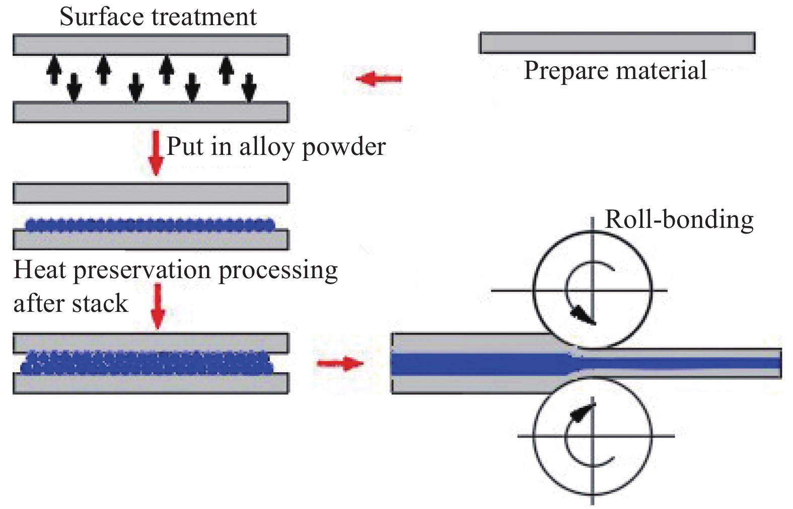
采用1.5 mm厚的7075-T6商业铝板材和6061铝合金颗粒(粒径<48 μm)为原材料,其化学成分见表1。首先将7075铝板材进行表面打磨抛光,去除氧化层后用酒精清洗,然后按照板材与粉末质量比为95∶5称量合金粉末,将粉末均匀的分布在板材上,随后将组坯放入马弗炉内,在415℃下保温2.5 h进行退火处理,然后将退火处理后的组坯取出,并以30%的下压量进行热轧复合后,获得6061p/7075层状铝基复合材料,其轧制复合示意图如图1所示。
表 1 7075铝板和6061铝颗粒化学成分Table 1. Chemical compositions of 7075 aluminum plates and 6061 aluminum particleswt% Element Zn Mg Cu Fe Si Mn Cr Ti Others Al 7075Al plates 6.08 2.55 1.82 0.23 0.09 0.09 0.21 0.03 0.05 Allowance 6061Al particle 0.25 0.9 0.2 0.7 0.5 0.15 0.1 0.15 0.05 Allowance ![]() 图 1 轧制制备6061p/7075层状铝基复合材料原理图Figure 1. Schematic diagram of rolling preparation 6061p/7075Al layered composites
图 1 轧制制备6061p/7075层状铝基复合材料原理图Figure 1. Schematic diagram of rolling preparation 6061p/7075Al layered composites采用附带能谱分析仪(EDS)的场发射式扫描电镜(SEM,日立S-4800)对样品的微观结构进行研究;采用型号为X’Pert PRO的X射线衍射分析仪(XRD)对样品进行物相分析;采用Insrton 8801万能试验机对样品进行拉伸测试,拉伸速率为2×10⁻⁴ s−1,所有拉伸试样均沿轧制方向取样,并用SEM观察拉伸断口形貌;在耐驰DMA 242E动态热机械分析仪上采用单悬臂应变控制模式测试样品的内耗值(常用应变滞后于应力的相位角tanδ来表征)和储能模量,样品测试的频率f为1 Hz,振幅A范围为0.1~150 μm,温度T区间为30~360℃,升温速率为5℃/min,测试样品尺寸为1.25 mm×4 mm×30 mm(厚×宽×长)。
2. 实验结果与分析
2.1 6061p/7075层状铝基复合材料的微观结构
图2为6061p/7075层状铝基复合材料的SEM图像。其中图2(a)、图2(b)和图2(c)分别为复合材料的整体形貌、界面处和6061铝颗粒层照片。由图2可见,6061p/7075层状铝基复合材料的上下两层分别为7075铝基体,中间为6061铝颗粒层,基体与合金颗粒层分层明显(图2(a));6061铝颗粒层与7075铝基体之间的界面结合良好,没有裂纹等缺陷产生(图2(b));合金颗粒层中6061铝颗粒之间由于所受挤压力大小不同而存在许多类似于泡沫铝的微孔隙结构,且6061铝颗粒层中存在大量的颗粒间界面(图2(c))。
![]() 图 2 6061p/7075层状铝基复合材料的SEM图像:整体形貌 (a)、界面 (b) 和6061铝颗粒层 (c)Figure 2. 6061p/7075Al layered composites SEM images of overall morphology (a), interface (b) and 6061Al particles layer (c)
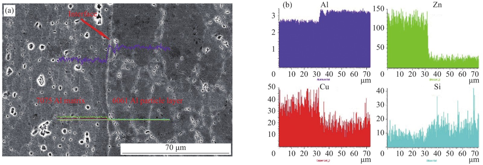
图 2 6061p/7075层状铝基复合材料的SEM图像:整体形貌 (a)、界面 (b) 和6061铝颗粒层 (c)Figure 2. 6061p/7075Al layered composites SEM images of overall morphology (a), interface (b) and 6061Al particles layer (c)图3为6061p/7075层状铝基复合材料界面处的EDS线扫描图。可以看出,6061铝颗粒层和7075铝基体之间的界面清晰,7075铝基体中的Zn和Cu元素均没有向6061铝颗粒层扩散,6061铝颗粒中的Si元素也没有向7075铝基体扩散,因此,6061铝颗粒层和7075铝基体之间的界面基本不存在元素扩散。
![]() 图 3 6061p/7075层状铝基复合材料界面处的EDS线扫描图Figure 3. EDS line scanning images of 6061p/7075Al layered composites interface
图 3 6061p/7075层状铝基复合材料界面处的EDS线扫描图Figure 3. EDS line scanning images of 6061p/7075Al layered composites interface图4为7075铝基体、6061铝合金颗粒和6061p/7075层状铝基复合材料的XRD图谱。可知,6061p/7075层状铝基复合材料中存在α-Al相、MgZn2相和Mg2Si相,7075铝合金主要相组成为α-Al相和MgZn2相,6061铝合金颗粒由α-Al相和Mg2Si相组成,对比分析发现复合材料中并没有新相生成。
![]() 图 4 7075铝基体、6061铝颗粒和6061p/7075层状铝基复合材料的XRD图谱Figure 4. XRD patterns of 7075Al, 6061Al particles and 6061p/7075Al layered composites
图 4 7075铝基体、6061铝颗粒和6061p/7075层状铝基复合材料的XRD图谱Figure 4. XRD patterns of 7075Al, 6061Al particles and 6061p/7075Al layered composites2.2 6061p/7075层状铝基复合材料的力学性能
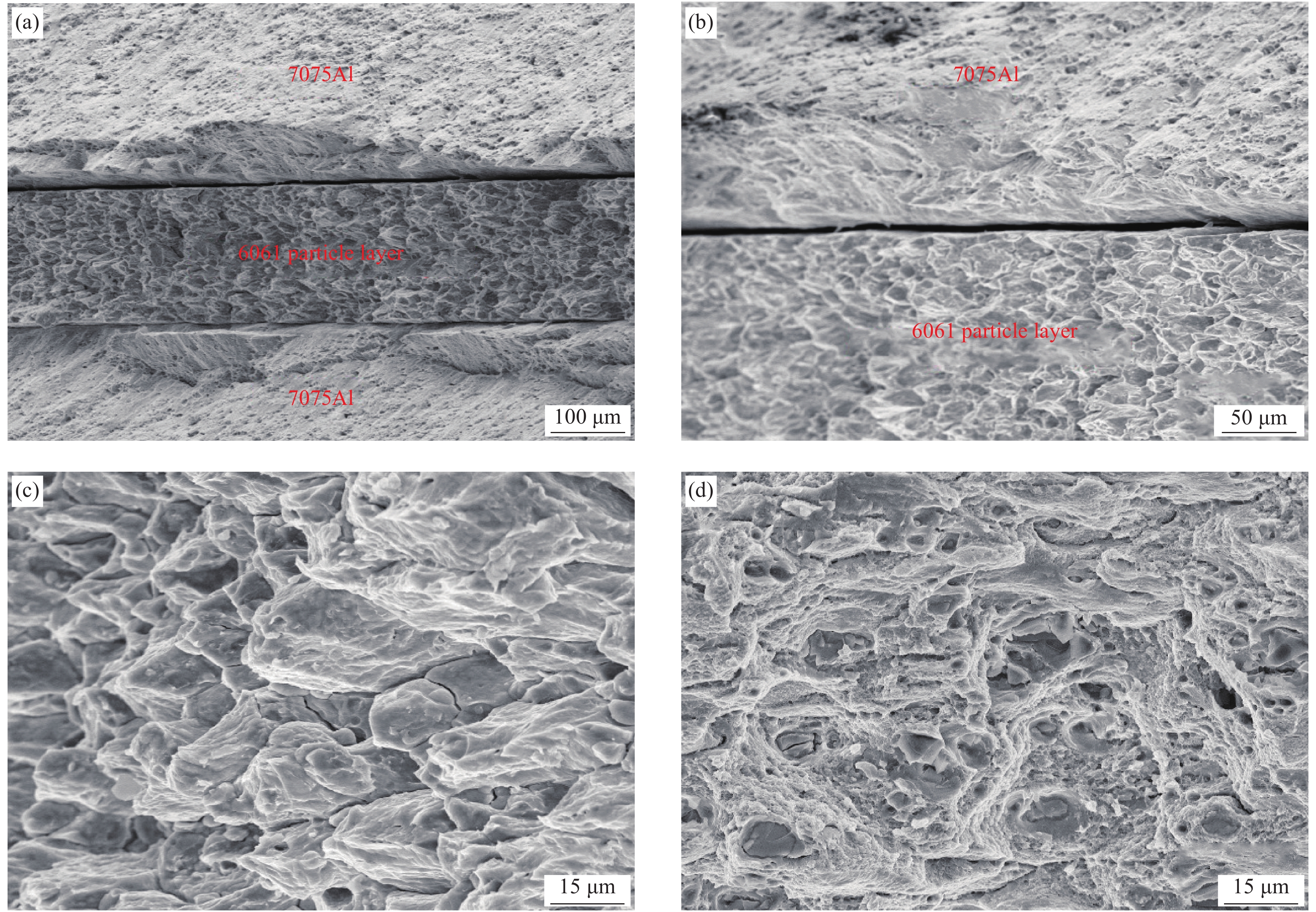
图5为6061p/7075层状铝基复合材料的拉伸断口形貌图。其中图5(a)为6061p/7075层状铝基复合材料的整体形貌,图5(b)为7075铝基体与合金颗粒层的界面处形貌,图5(c)和图5(d)分别为6061铝颗粒层和7075铝基体的形貌。从图5(a)观察到,复合材料断口整体形貌呈现凹型,这说明在拉伸过程中7075铝基体与6061铝合金颗粒层受到的拉应力不同步,中间合金颗粒层先于铝基体发生断裂;从图5(b)观察发现,7075铝基体与6061铝合金颗粒层的界面处存在分离开裂现象;由图5(c)可见,6061铝颗粒层的断裂方式为6061铝颗粒的粘结相断裂和解理断裂,这是由于中间合金颗粒层在拉伸载荷作用下,颗粒间的弱结合界面会先发生脱开现象(粘结相断裂),脱开的界面失去了载荷传递的能力,同时,另一些结合较强的颗粒间界面能充分传递载荷,这些颗粒则会在此较高应力下发生解理断裂;由图5(d)可知,7075铝基体中存在大量的韧窝,断裂方式表现为韧性断裂。
![]() 图 5 6061p/7075层状铝基复合材料拉伸断口的整体 (a)、界面 (b)、6061铝颗粒层 (c) 和7075铝基体 (d) 形貌Figure 5. Tensile fracture morphologies of overall morphology (a), interface (b), 6061Al particles layer (c) and 7075Al matrix (d) of 6061p/7075Al layered composites
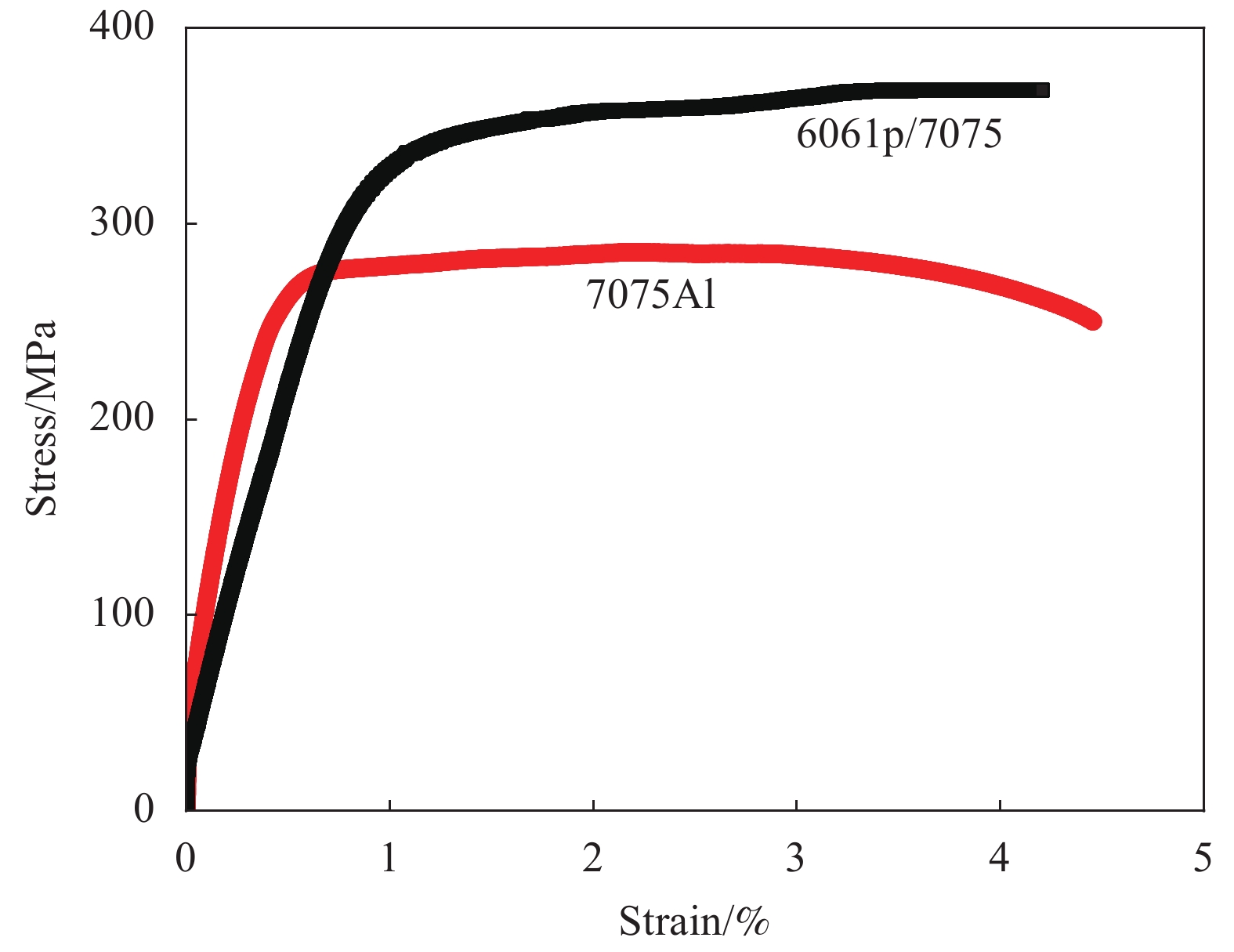
图 5 6061p/7075层状铝基复合材料拉伸断口的整体 (a)、界面 (b)、6061铝颗粒层 (c) 和7075铝基体 (d) 形貌Figure 5. Tensile fracture morphologies of overall morphology (a), interface (b), 6061Al particles layer (c) and 7075Al matrix (d) of 6061p/7075Al layered composites图6为7075铝基体和6061p/7075层状铝基复合材料的应力-应变曲线。可知,6061p/7075层状铝基复合材料具有较高的屈服强度,复合材料最大抗拉强度为370.5 MPa,比7075铝基体最大抗拉强度(285.4 MPa)提高了30%,其延伸率为4.2%,较7075铝基体略有下降。在拉伸过程中,6061铝颗粒层存在大量的颗粒间界面(见图2(b)),这些界面对位错有阻碍作用,位错在界面处的塞积,引发位错强化作用[17],有利于改善复合材料的屈服强度。
![]() 图 6 7075铝基体和6061p/7075铝基复合材料应力-应变曲线Figure 6. Stress-strain curves of 7075Al matrix and 6061p/7075Al layered composites
图 6 7075铝基体和6061p/7075铝基复合材料应力-应变曲线Figure 6. Stress-strain curves of 7075Al matrix and 6061p/7075Al layered composites6061铝颗粒层与7075铝基体之间的结合界面类似于层合板的层间界面[18],在拉伸过程中,6061铝颗粒层与7075铝基体的力学性能差异导致界面失配,使6061铝颗粒层与7075铝基体结合界面处应力集中,界面因层间剪切应力作用而发生大面积开裂(见图5(a)和图5(b)),破坏表现为层间剥离破坏(即层间剪切失效);随着拉伸应变量的增加,6061铝颗粒层发生脆性断裂,而层间界面裂纹不断扩展,界面应力载荷逐渐下降,达到稳定扩展阶段,持续发生界面损伤积累,直至最后伴随7075铝基体的塑性变形失效导致复合材料发生宏观断裂[19],在这个过程中层间界面需要额外的能量,导致复合材料整体的能量吸收增大,有利于改善复合材料的抗拉强度[20-21],层间界面失效与铝基体塑性变形失效的协同作用,使6061p/7075层状铝基复合材料的抗拉强度优于7075铝基体。
2.3 6061p/7075层状铝基复合材料的阻尼性能
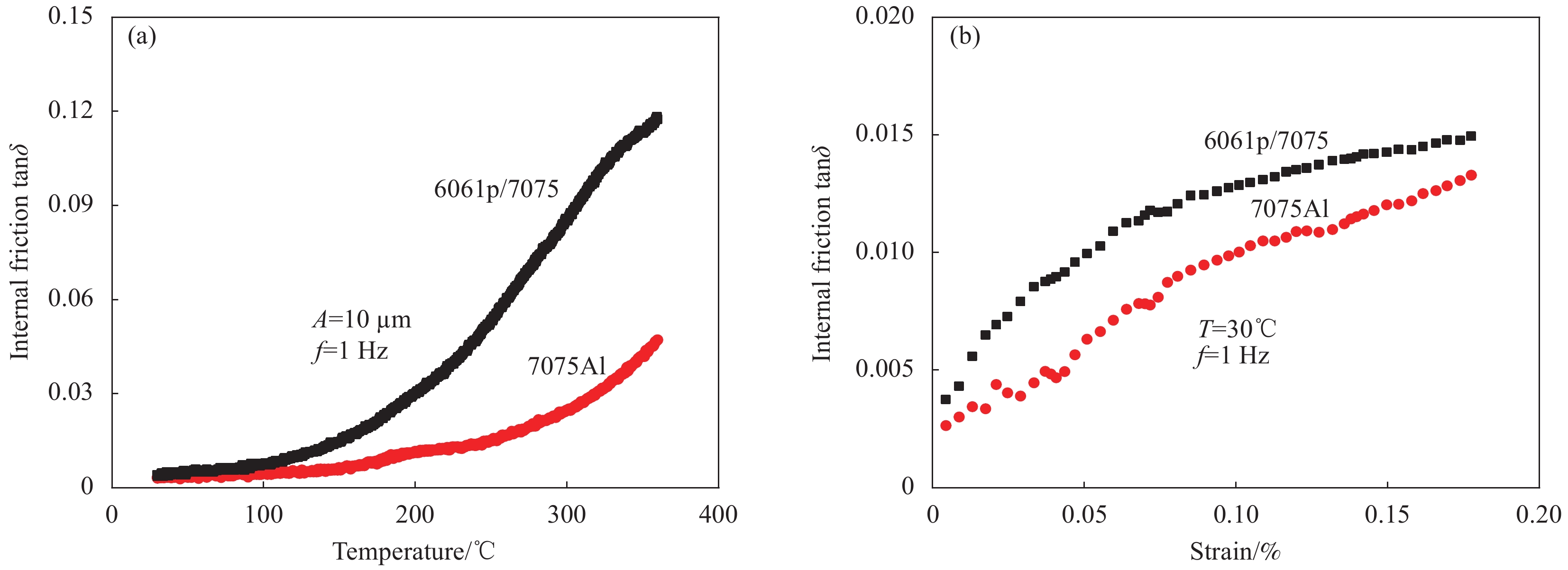
图7为7075铝基体和6061p/7075层状铝基复合材料的阻尼测试曲线图,其中图7(a)为样品在振动频率为1 Hz、振幅为10 μm条件下的内耗-温度曲线图,图7(b)为样品在振动频率为1 Hz、温度为30℃条件下的内耗-应变曲线图。由图7(a)可知,7075铝基体和6061p/7075铝基复合材料的内耗值均随着温度的升高而增大;当温度高于200℃时,随着温度的升高,6061p/7075层状铝基复合材料的内耗值增幅显著,7075铝基体也表现出相同的趋势,但6061p/7075层状铝基复合材料的内耗值明显高于7075铝基体;在360℃时,复合材料的内耗值高达0.117,比7075铝基体的内耗值(0.047)提高了149%,其阻尼性能明显优于7075铝基体。
![]() 图 7 7075铝基体和6061p/7075层状铝基复合材料的内耗-温度曲线 (a) 和内耗-应变曲线 (b)Figure 7. Internal friction-temperature curves (a) and internal friction-strain curves (b) of 7075Al matrix and 6061p/7075Al layered compositesA—Vibration amplitude; f—Frequency; T—Temperature
图 7 7075铝基体和6061p/7075层状铝基复合材料的内耗-温度曲线 (a) 和内耗-应变曲线 (b)Figure 7. Internal friction-temperature curves (a) and internal friction-strain curves (b) of 7075Al matrix and 6061p/7075Al layered compositesA—Vibration amplitude; f—Frequency; T—Temperature在中高温条件下,晶界和界面结合能降低,晶界与界面一起滑移,导致合金中晶界和界面阻尼机制起主要贡献作用[22-23]。6061p/7075层状铝基复合材料的合金颗粒层中存在大量的颗粒间界面(见图2(b)),这些界面在高温振动过程中发生非弹性迁移,将机械能转化为内能,有利于提高复合材料的高温阻尼性能。另外,6061铝颗粒层由6061铝颗粒骨架和微孔隙组成(图2(c)),孔隙周围的应力集中、孔隙/颗粒界面处动态模量的差异及孔隙的不均匀变形促进了机械能向内能的转换[24-25],从而提高了6061p/7075层状铝基复合材料的阻尼性能。
由图7(b)可见,7075铝基体和6061p/7075层状铝基复合材料的内耗值均随着应变量的升高而逐渐增大,且复合材料的内耗值高于7075铝基体。当应变量为0.16%时,复合材料的内耗值为0.015,比7075铝基体的内耗值(0.013)高15%。在低温条件下,位错阻尼是铝合金的主要阻尼机制,随着应变量的增加,合金中会有更多的位错发生滑移,使合金的内耗值增大;同时,6061铝颗粒层中存在大量的颗粒间界面,在振动形变过程中,这些界面周围产生形变位错源,使合金颗粒层中位错增殖,有利于引发更多的位错阻尼,从而改善6061p/7075铝基复合材料的阻尼性能。
2.4 6061p/7075层状铝基复合材料的储能模量
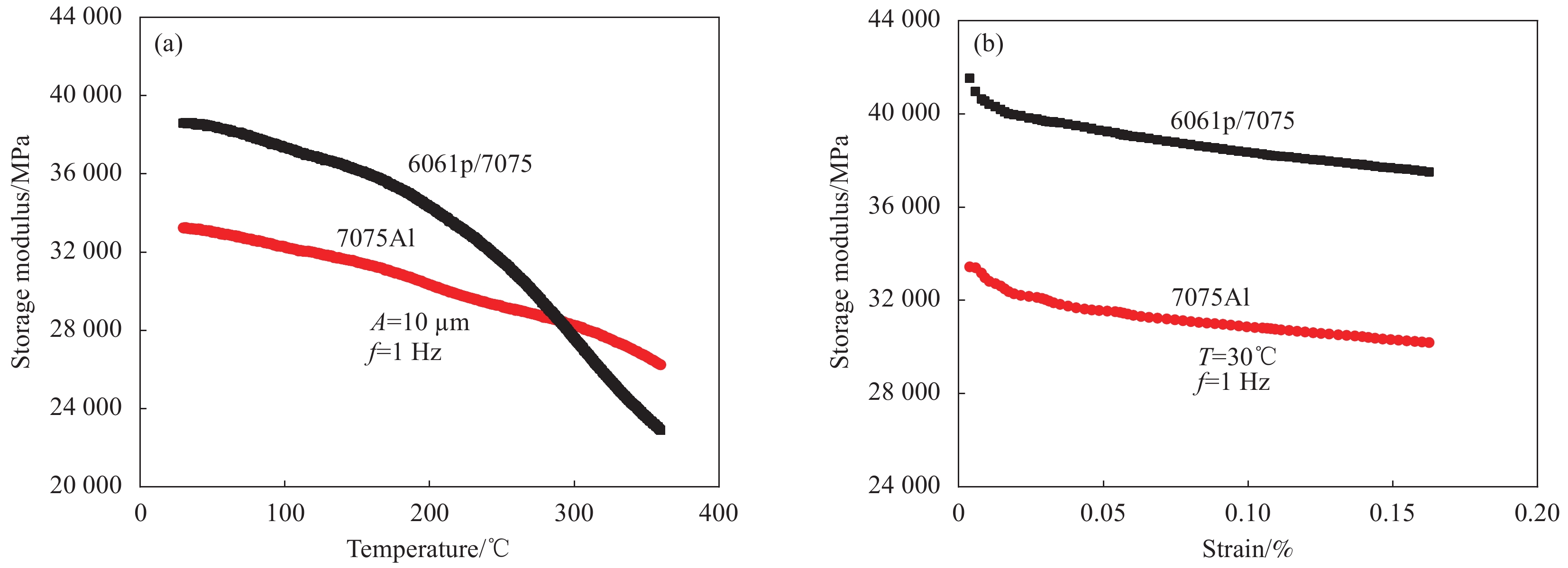
图8为7075铝基体和6061p/7075层状铝基复合材料的储能模量测试曲线,其中图8(a)为样品在振动频率为1 Hz、振幅为10 μm条件下的储能模量-温度曲线,图8(b)为样品在振动频率f为1 Hz、温度T为30℃条件下的内耗-应变曲线。由图8(a)可知,两种材料的储能模量均随着温度的升高而降低,当温度低于289℃时,6061p/7075层状铝基复合材料的储能模量高于7075铝基体,在30℃时,复合材料的储能模量为38601 MPa,比7075铝基体的储能模量(33230 MPa)高16%。由图8(b)可知,两种材料的储能模量都随着应变的升高而降低,6061p/7075层状铝基复合材料的储能模量明显高于7075铝基体。材料的存储模量是以形变后残留内应力和应变方式存在的[26-27],6061p/7075层状铝基复合材料合金颗粒层中存在大量的颗粒间界面,在振动形变过程中,这些界面对位错运动起阻碍作用,在界面处位错塞积造成应力集中,从而使变形后的残余内应力增加,有利于提高复合材料的存储模量。
![]() 图 8 7075铝基体和6061p/7075层状铝基复合材料的储能模量-温度曲线 (a) 和储能模量-应变曲线 (b)Figure 8. Storage modulus-temperature curves (a) and storage modulus-strain curves (b) of 7075Al matrix and 6061p/7075Al layered composites
图 8 7075铝基体和6061p/7075层状铝基复合材料的储能模量-温度曲线 (a) 和储能模量-应变曲线 (b)Figure 8. Storage modulus-temperature curves (a) and storage modulus-strain curves (b) of 7075Al matrix and 6061p/7075Al layered composites3. 结 论
(1) 采用热轧复合技术在7075铝基体中引入6061铝颗粒层,制备出6061p/7075层状铝基复合材料;复合材料中7075铝基体与6061铝颗粒层之间界面清晰,结合良好,颗粒层中存在大量的颗粒间界面和微小孔隙;7075铝基体与6061铝颗粒层间的界面处没有发生明显的元素扩散,复合材料中无新相生成。
(2) 6061p/7075层状铝基复合材料中颗粒层的断裂方式主要为铝颗粒的粘结相断裂和解理断裂,铝基体的断裂方式为韧性断裂;6061p/7075层状铝基复合材料的最大抗拉强度为370.5 MPa,比7075铝基体提高了30%,层间界面失效和铝基体塑性变形失效的协同作用,使复合材料的抗拉强度优于7075铝基体。
(3) 6061p/7075层状铝基复合材料的内耗值分别随着温度和应变量的升高而增大,在360℃时,复合材料的内耗值达到0.117,比7075铝基体提升了149%;在7075铝合金中引入6061铝颗粒层会导致复合材料中存在大量的界面和微孔隙,在高温振动过程中,这些界面和孔隙引发的协同阻尼行为能有效地改善铝合金的高温阻尼性能。
(4) 6061p/7075层状铝基复合材料的储能模量分别随着温度和应变量的升高而逐渐降低,当温度低于289℃时,复合材料的储能模量高于7075铝基体;6061铝颗粒层中大量的颗粒间界面对位错运动起阻碍作用,使变形后的残余内应力增加,提高了复合材料的存储模量。
-
![]()
图 4 CFRP加固钢板双剪试件界面破坏模式
Figure 4. Interfacial failure modes of double-lap joint specimen of CFRP-strengthened steel plate
![]()
图 5 通过偏心拉伸实现的CFRP加固钢板单剪搭接接头
Figure 5. Single-lap joint of CFRP-strengthened steel plate subjected to eccentric loading
M—Bending moment
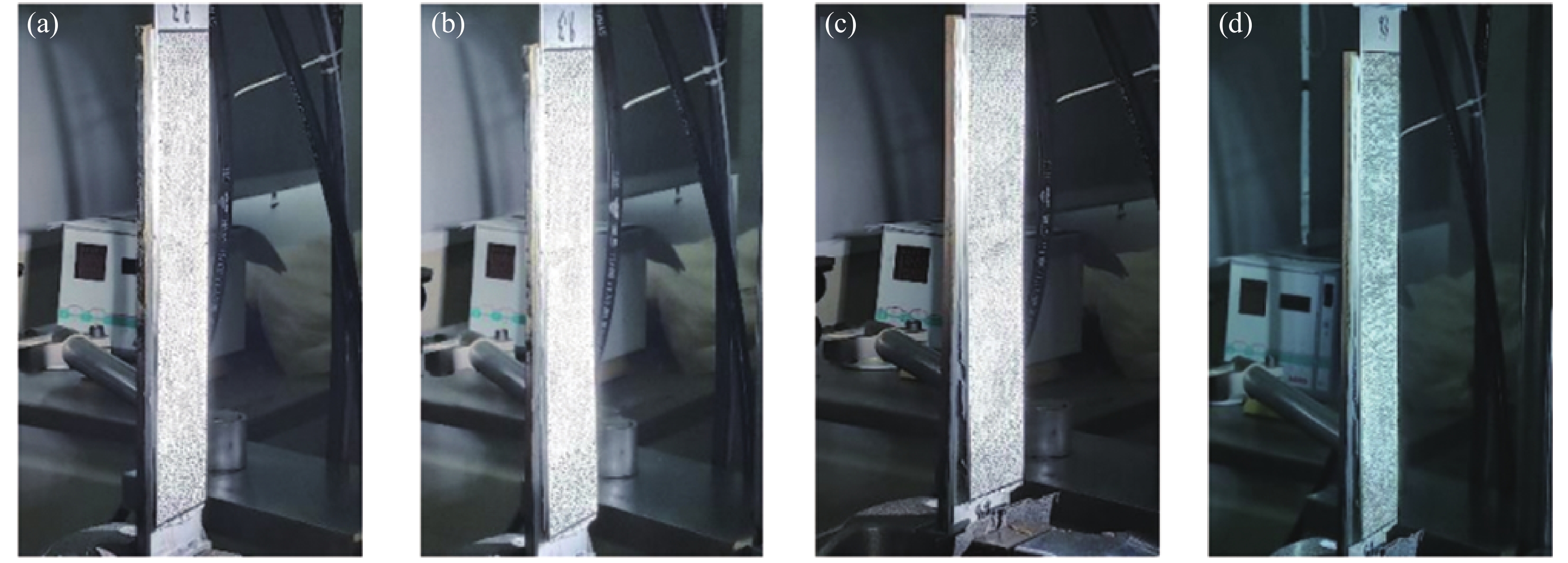
![]()
图 6 CFRP加固钢板单剪试件破坏过程
Figure 6. Failure process of single-lap joint of CFRP-strengthened steel plate
![]()
图 7 CFRP加固钢板单剪试件胶层/CFRP界面脱粘
Figure 7. Adhesion failure at adhesive/CFRP interface of single-lap joint of CFRP-strengthened steel plate
![]()
图 8 CFRP加固钢板双剪试件的荷载-位移曲线
Figure 8. Load-displacement curves of double-lap joints of CFRP-strengthened steel plate
![]()
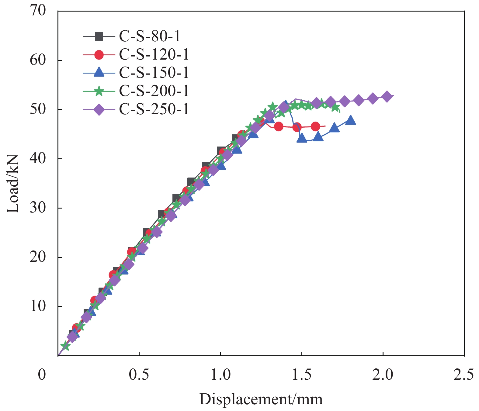
图 9 CFRP加固钢板单剪试件的荷载-位移曲线
Figure 9. Load-displacement curves of single-lap joints of CFRP-strengthened steel plate
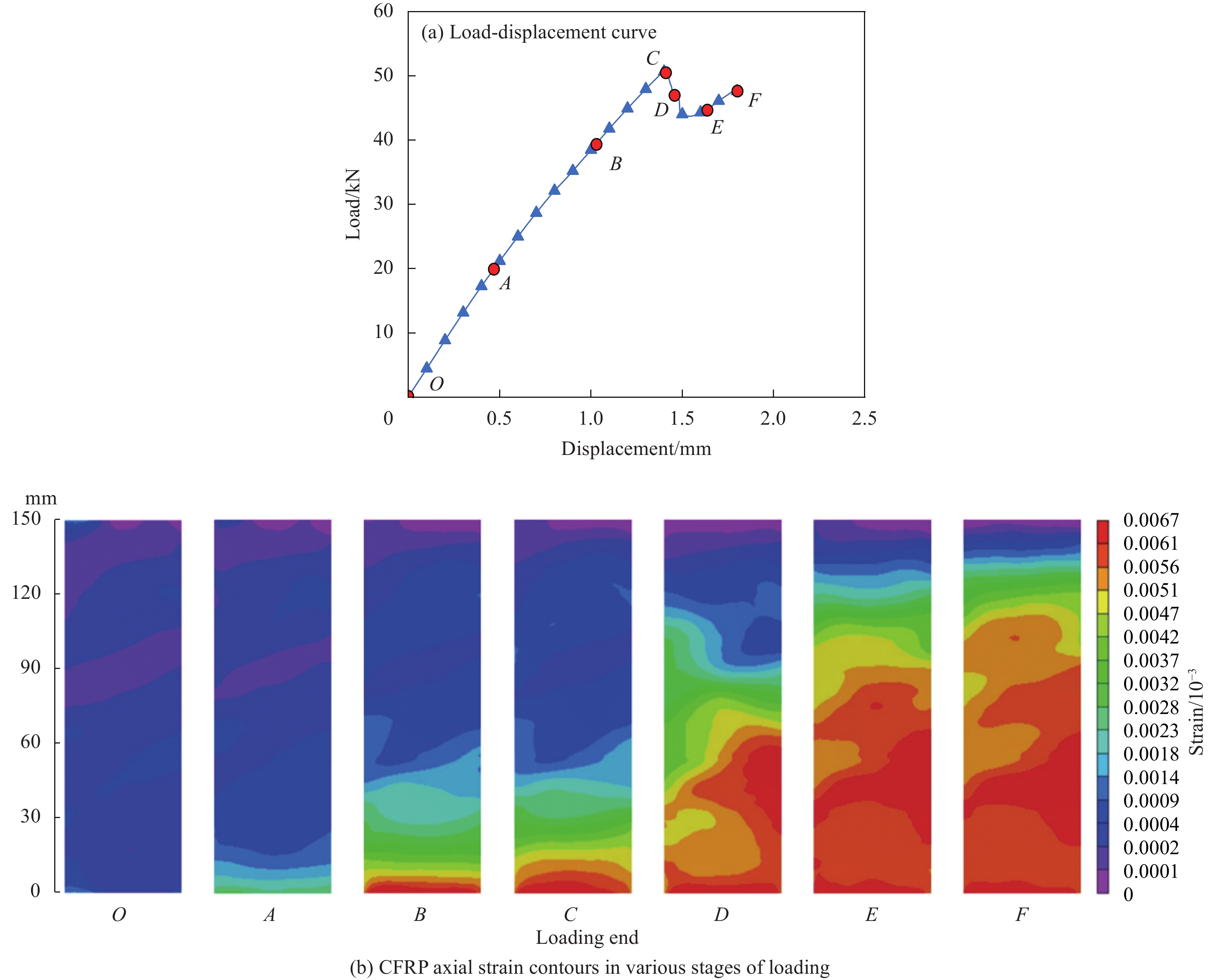
![]()
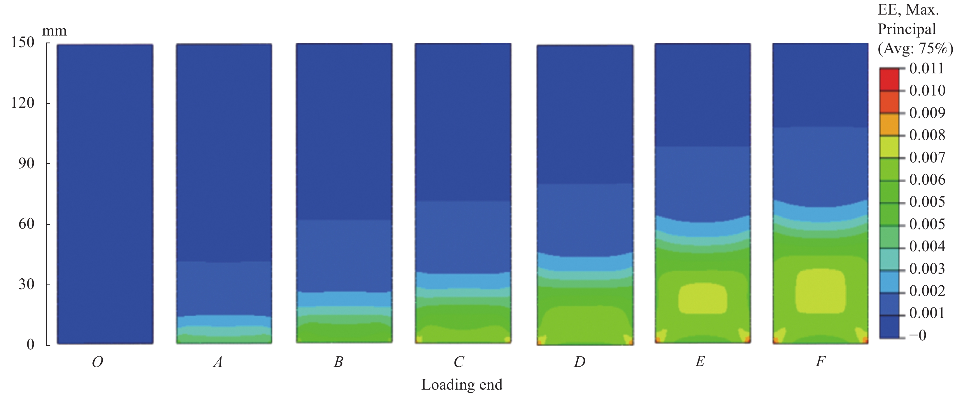
图 10 C-S-150-1试件的荷载-位移曲线及不同加载时刻CFRP轴向应变云图
Figure 10. Load-displacement curve and axial strain contours in CFRP of specimen C-S-150-1
![]()
图 11 C-S-200-1试件的荷载-位移曲线及不同加载时刻CFRP轴向应变云图
Figure 11. Load-displacement curve and axial strain contours in CFRP of specimen C-S-200-1
![]()
图 12 C-S-250-1试件的荷载-位移曲线及不同加载时刻CFRP轴向应变云图
Figure 12. Load-displacement curve and axial strain contours in CFRP of specimen C-S-250-1
![]()
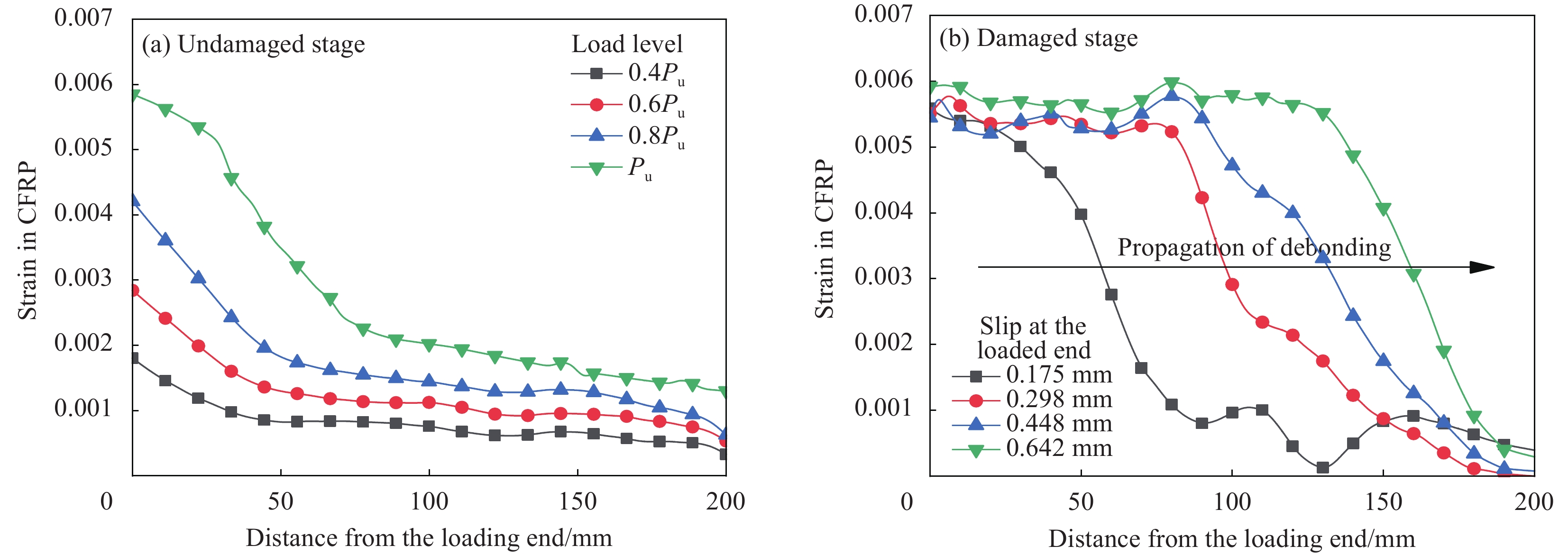
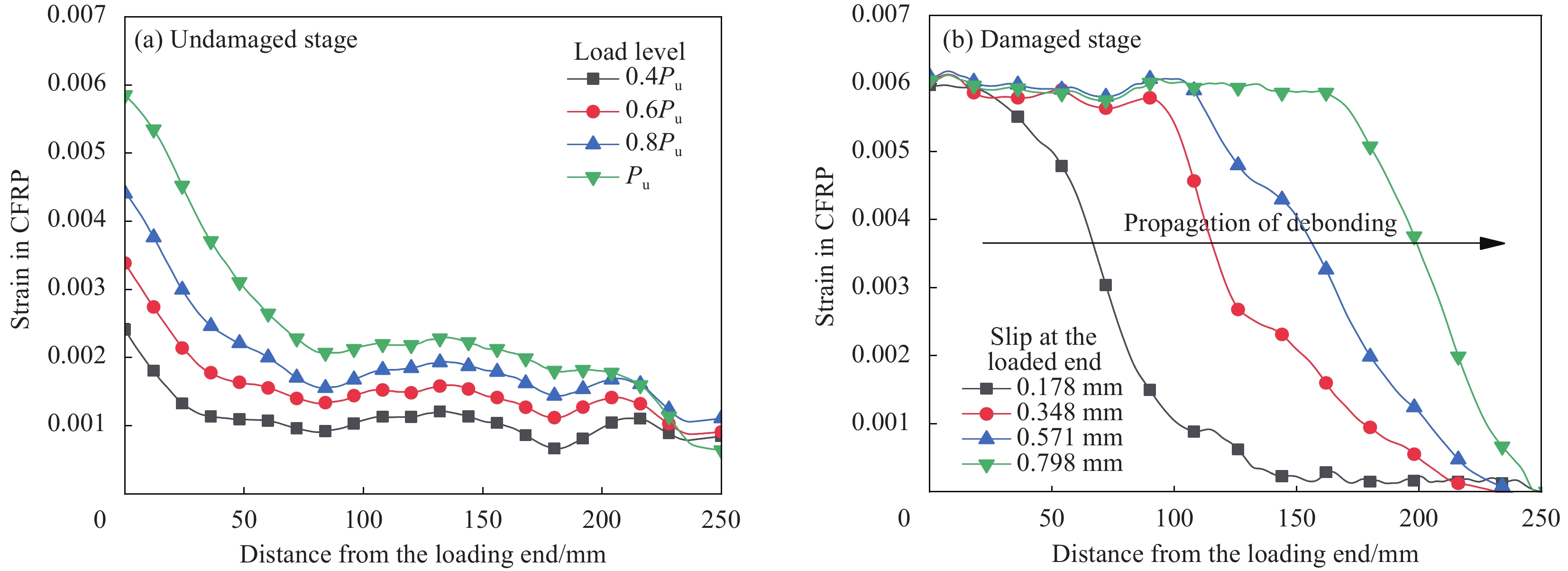
图 13 C-S-150-1试件的CFRP轴向应变分布曲线
Figure 13. Axial strain distribution curves in CFRP of specimen C-S-150-1
![]()
图 14 C-S-200-1试件的CFRP轴向应变分布曲线
Figure 14. Axial strain distribution curves in CFRP of specimen C-S-200-1
![]()
图 15 C-S-250-1试件的CFRP轴向应变分布曲线
Figure 15. Axial strain distribution curves in CFRP of specimen C-S-250-1
![]()
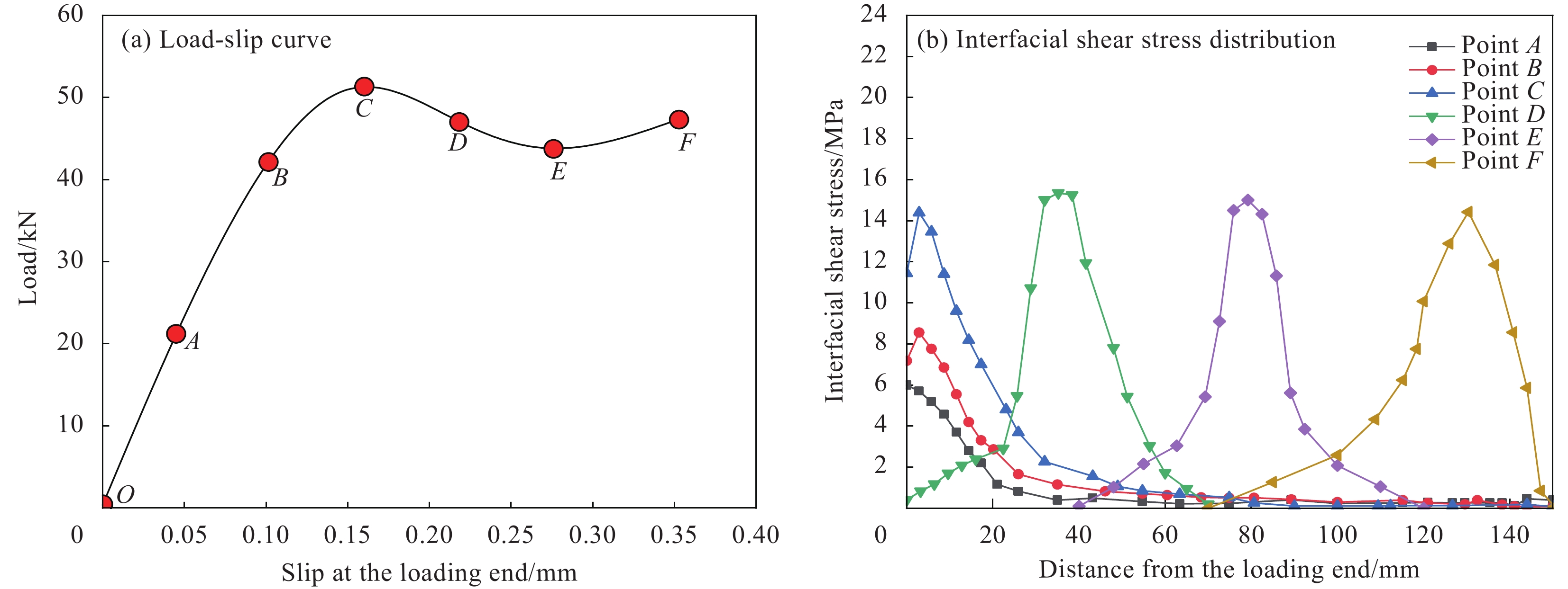
图 16 C-S-150-1试件的荷载-滑移曲线和界面剪应力分布曲线
Figure 16. Load-slip curve and interfacial shear stress distribution curves of specimen C-S-150-1
![]()
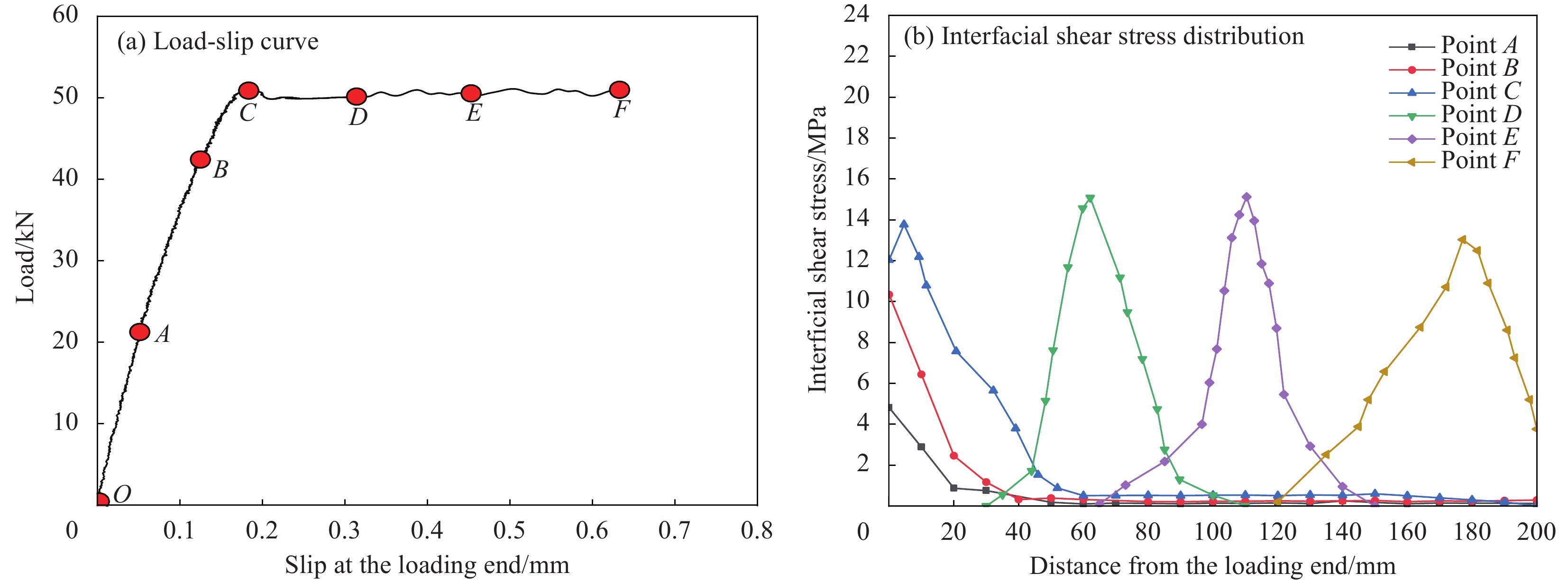
图 17 C-S-200-1试件的荷载-滑移曲线和界面剪应力分布曲线
Figure 17. Load-slip curve and interfacial shear stress distribution curves of specimen C-S-200-1
![]()
图 18 C-S-250-1试件荷载-滑移曲线和界面剪应力分布曲线
Figure 18. Load-slip curve and interfacial shear stress distribution curves of specimen C-S-250-1
![]()
图 19 CFRP加固钢板粘结-滑移曲线
Figure 19. Bond-slip curves of CFRP-strengthened steel plate
τmax−Peak shear stress; δ1−Corresponding slip to peak shear stress; δf−Ultimate slip
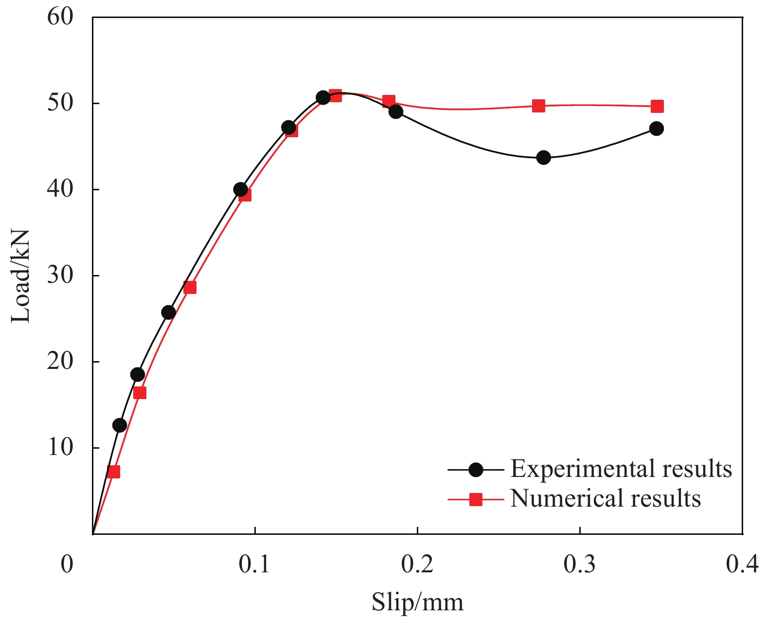
![]()
图 22 C-S-150-1试件荷载-滑移曲线对比
Figure 22. Comparison of load-slip curves of specimen C-S-150-1
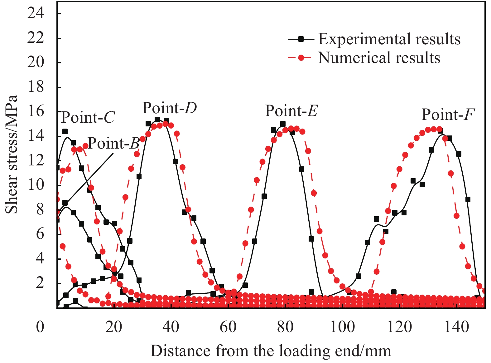
![]()
图 23 C-S-150-1试件界面剪应力分布对比
Figure 23. Comparison of interfacial shear stress distribution of specimen C-S-150-1
表 1 材料力学性能
Table 1 Material properties
Material Young’s modulus/GPa Tension strength/MPa Shear strength/MPa Yield strength/MPa Poisson’s ratio Elongation/% Q235 206 400 − 235 0.3 29.4 CFRP 150 1 230 − − 0.28 1.6 Adhesive 3.2 30 17 − 0.35 1.32 Note: CFRP—Carbon fiber reinforce polymer.  下载: 导出CSV
表 2 不同粘结长度CFRP加固钢板双剪试件的极限载荷及失效模式
Table 2 Ultimate load and failure modes of double-lap joint specimens of CFRP-strengthened steel plate with different bond lengths
Specimen Measured
adhesive thickness/mmBond
length/mmLength of
steel plate/mmUltimate
load/kNFailure
modeC-S-80-1 1.01 80 200 45.76 C+D C-S-80-2 0.99 80 200 45.32 C+D C-S-80-3 0.92 80 200 44.73 C+D C-S-80-4 0.91 80 200 45.12 C+D C-S-120-1 1.02 120 250 47.55 C+D+E C-S-120-2 1.03 120 250 47.87 C+D C-S-120-3 0.93 120 250 46.92 C+D C-S-120-4 0.90 120 250 47.38 C+D C-S-150-1 1.03 150 300 50.74 C+D C-S-150-2 1.02 150 300 51.42 C+D C-S-150-3 0.93 150 300 50.39 C+D C-S-150-4 0.96 150 300 50.79 C+D C-S-200-1 0.97 200 350 51.23 C+D C-S-200-2 1.09 200 350 52.21 C+D C-S-200-3 1.10 200 350 51.07 C+D C-S-200-4 0.97 200 350 51.78 C+D C-S-250-1 0.99 250 350 51.92 C+D C-S-250-2 1.03 250 350 51.08 C+D C-S-250-3 0.98 250 350 52.03 C+D C-S-250-4 0.96 250 350 51.01 C+D Notes: C—Cohesion failure in adhesive; D—Adhesion failure at adhesive/CFRP interface; E—Adhesion failure at adhesive/steel interface; C-S—CFRP-steel.
下载: 导出CSV
表 3 不同粘结长度CFRP加固钢板双剪试件的粘结-滑移本构参数
Table 3 Parameters in bond-slip law for double-lap joint specimens of CFRP-strengthened steel plate with different bond lengths
Specimen τmax/MPa δ1/mm δf/mm Gf/(N·mm−1) le/mm C-S-150-1 14.6 0.065 0.178 1.299 78.56 C-S-150-2 14.1 0.067 0.184 1.297 81.23 C-S-150-3 13.7 0.063 0.177 1.212 80.52 C-S-150-4 13.4 0.061 0.174 1.165 80.52 C-S-200-1 14.5 0.062 0.174 1.261 77.61 C-S-200-2 14.0 0.068 0.183 1.281 81.58 C-S-200-3 13.6 0.059 0.170 1.156 78.87 C-S-200-4 13.7 0.060 0.169 1.157 78.64 C-S-250-1 14.2 0.070 0.182 1.789 81.27 C-S-250-2 14.3 0.069 0.184 1.823 81.07 C-S-250-3 13.6 0.043 0.165 1.124 74.38 C-S-250-4 13.7 0.093 0.154 1.054 83.15 Notes: Gf—Fracture energy; le—Effective bond length.
下载: 导出CSV
-
[1] 岳清瑞, 侯兆新. 对我国钢结构发展的思考[J]. 工程建设标准化, 2017(5):48-56. YUE Qingrui, HOU Zhaoxin. Thoughts on the development of steel structures in China[J]. Standardization of Engineering Construction,2017(5):48-56(in Chinese).
[2] 程璐, 冯鹏, 徐善华, 等. CFRP加固钢结构抗疲劳技术研究综述[J]. 玻璃钢/复合材料, 2013(4):58-62. CHENG Lu, FENG Peng, XU Shanhua, et al. Review on anti-fatigue technology of steel structure strengthened by CFRP[J]. Fiber Reinforced Plastics/Composites,2013(4):58-62(in Chinese).
[3] HOSSEINI A, MOSTOFINEJAD D. Effective bond length of FRP-to-concrete adhesively-bonded joints: Experimental evaluation of existing models[J]. International Journal of Adhesion & Adhesives,2014,48:150-158.
[4] ZHANG P, LEI D, REN Q, et al. Experimental and numerical investigation of debonding process of the FRP plate-concrete interface[J]. Construction and Building Materials,2019,235:117457.
[5] 李趁趁, 于爱民, 高丹盈, 等. 侵蚀环境下FRP条带加固锈蚀钢筋混凝土圆柱轴心受压试验[J]. 复合材料学报, 2020, 37(8):2015-2028. LI Chenchen, YU Aimin, GAO Danying, et al. Experimental study on axial compression of corroded reinforced concrete columns strengthened with FRP strips under erosion environment[J]. Acta Materiae Compositae Sinica,2020,37(8):2015-2028(in Chinese).
[6] SEN R. Advances in the application of FRP for repairing corrosion damage[J]. Progress in Structural Engineering & Materials,2003,5(2):99-113.
[7] ZHAO X L, ZHANG L. State-of-the-art review on FRP strengthened steel structures[J]. Steel Construction,2007,29(8):1808-1823.
[8] TENG J G, YU T, FERNANDO D. Strengthening of steel structures with fiber-reinforced polymer composites[J]. Journal of Constructional Steel Research,2012,78:131-143. DOI: 10.1016/j.jcsr.2012.06.011
[9] BOCCIARELLI M, COLOMBI P, FAVA G, et al. Fatigue performance of tensile steel members strengthened with CFRP plates[J]. Steel Construction,2009,87(4):334-343.
[10] YU T, FERNANDO D, TENG J G, et al. Experimental study on CFRP-to-steel bonded interfaces[J]. Composites Part B: Engineering,2012,43(5):2279-2289. DOI: 10.1016/j.compositesb.2012.01.024
[11] WU C, ZHAO X L, CHIU W K, et al. Effect of fatigue loading on the bond behaviour between UHM CFRP plates and steel plates[J]. Composites Part B: Engineering,2013,50:344-353. DOI: 10.1016/j.compositesb.2013.02.040
[12] WANG H T, WU G, JIANG J B. Fatigue behavior of cracked steel plates strengthened with different CFRP systems and configurations[J]. Journal of Composites for Construction,2016,20(3):04015078. DOI: 10.1061/(ASCE)CC.1943-5614.0000647
[13] NGUYEN T C, BAI Y, ZHAO X L, et al. Curing effects on steel/CFRP double strap joints under combined mechanical load, temperature and humidity[J]. Construction & Building Materials,2013,40:899-907.
[14] GRAMMATIKOS S A, JONES R G, EVERNDEN M, et al. Thermal cycling effects on the durability of a pultruded GFRP material for off-shore civil engineering structures[J]. Composite Structures,2016,153:297-310. DOI: 10.1016/j.compstruct.2016.05.085
[15] MOHSEN H, REZA H, MOHAMMAD AL-E. Durability of CFRP/steel joints under cyclic wet-dry and freeze thaw conditions[J]. Composites Part B: Engineering,2017,126:211-226. DOI: 10.1016/j.compositesb.2017.06.011
[16] WANG Y, ZHENG Y, LI J, et al. Experimental study on tensile behaviour of steel plates with centre hole strengthened by CFRP plates under marine environment[J]. International Journal of Adhesion and Adhesives,2018:18-26.
[17] BISCAIA H C, CHASTRE C. Theoretical analysis of fracture in double overlap bonded joints with FRP composites and thin steel plates[J]. Engineering Fracture Mechanics,2018:435-460.
[18] CERONI F, IANNICIELLO, et al. Bond behavior of FRP carbon plates externally bonded over steel and concrete elements: Experimental outcomes and numerical investigations[J]. Composites Part B: Engineering, 2016, 92: 434-446.
[19] HE J, XIAN G. Debonding of CFRP-to-steel joints with CFRP delamination[J]. Composite Structures,2016,153:12-20. DOI: 10.1016/j.compstruct.2016.05.100
[20] PANG Y, WU G, WANG H, et al. Experimental study on the bond behavior of CFRP-steel interfaces under quasi-static cyclic loading[J]. 2019, 140: 426-437.
[21] LIU M, DAWOOD M. A closed-form solution of the interfacial stresses and strains in steel beams strengthened with externally bonded plates using ductile adhesives[J]. Engineering Structures,2018,154:66-77. DOI: 10.1016/j.engstruct.2017.10.054
[22] YANG, Y M, SILVA, et al. CFRP-to-steel bonded joints subjected to cyclic loading: An experimental study[J]. Composites Part B: Engineering,2018,146:28-41. DOI: 10.1016/j.compositesb.2018.03.039
[23] 杨怡, 黄炽辉, 吴作栋. 基于双剪实验的CFRP-钢板界面粘结性能研究[J]. 中山大学学报(自然科学版):1-9. [2020-11-05]. 网址: doi.org/10.13471/j.cnki.acta.snus.2020.07.14.2020B082. YANG Yi, HUANG Chihui, WU Zuodong. Study on bonding performance of CFRP-steel plate interface based on double shear test[J]. Acta Scientiarum Naturalium Universitatis Sunyatseni (Natural Science):1-9. [2020-11-05]. Website: doi.org/10.13471/j.cnki.acta.snus.2020.07.14.2020B082(in Chinese).
[24] CARLONI C, SUBRAMANIAM K V. Direct determination of cohesive stress transfer during debonding of FRP from concrete[J]. Composite Structures,2010,93(1):184-192. DOI: 10.1016/j.compstruct.2010.05.024
[25] WANG H T, WU G, DAI Y T, et al. Experimental study on bond behavior between CFRP plates and steel substrates using digital image correlation[J]. Journal of Composites for Construction,2016,20(6):04016054. DOI: 10.1061/(ASCE)CC.1943-5614.0000701
[26] YANG Y, BISCAIA H, CHASTRE C, et al. Bond characteristics of CFRP-to-steel joints[J]. Journal of Constructional Steel Research,2017,138:401-419. DOI: 10.1016/j.jcsr.2017.08.001
[27] ARDALAN H, ELYAS G, MATTHIAS W, et al. Short-term bond behavior and debonding capacity of prestressed CFRP composites to steel substrate[J]. Engineering Structures,2018,176:935-947. DOI: 10.1016/j.engstruct.2018.09.025
[28] LU X Z, TENG J G, YE L P, et al. Bond-slip models for FRP sheets/plates bonded to concrete[J]. Engineering Structures,2005,27(6):920-937. DOI: 10.1016/j.engstruct.2005.01.014
[29] YUAN H, TENG J G, SERACINO R, et al. Full-range behavior of FRP-to-concrete bonded joints[J]. Engineering Structures,2003,26(5):553-565.
-
期刊类型引用(7)
1. 王东,董传瑞,朱红民,丁国元,黄河源,赵美英. 温度对金属-复合材料混合多螺栓连接力学性能的影响. 复合材料学报. 2024(06): 3248-3257 .  本站查看
本站查看
2. 郭飞燕,肖世宏,肖庆东,王仲奇. 面向性能保障的新一代飞机结构装配质量控制技术. 机械工程学报. 2024(16): 412-428 . 百度学术
3. 张景杭,姜绍飞,夏樟华,林永福,洪俊贤. 内置薄钢板的纤维复合材料接头连接性能. 福州大学学报(自然科学版). 2024(05): 587-594 . 百度学术
4. 卢弈先,曹东风,胡海晓,蔡伟,王伟伦,郑凯东,冀运东,李书欣. 高温环境对胶螺混合连接复合材料结构失效行为的影响. 复合材料学报. 2024(12): 6844-6857 . 本站查看
5. 雷凯,王彬文,成竹,邓文亮,吴敬涛. 飞机多钉壁板混合结构热应力分析与验证. 应用力学学报. 2023(01): 40-47 . 百度学术
6. 王海波,付宇,万帅,郑凯,王明,蔡计杰. 碳纤维复合材料铆胶连接强度研究. 合成纤维. 2022(03): 44-49 . 百度学术
7. 孙家豪,齐振超,陈文亮. 制孔偏差对铝合金单钉双剪连接性能的影响. 现代制造工程. 2022(11): 97-102 . 百度学术
其他类型引用(4)
-


计量
- 文章访问数: 1662
- HTML全文浏览量: 642
- PDF下载量: 127
- 被引次数: 11
