In-plane permeability characterization of fiber fabric based on digital image technology
-
摘要: 材料渗透率的表征受其结构空间离散性和求解方式准确性的严重影响。基于数字图像技术,评估了纤维织物渗透率的空间分布,并探讨了阶梯铺层对灌注工艺的影响。首先,从恒压单向注射实验的视频流中动态提取了流动前沿的流速分布和流动前沿角,通过织物渗透率与结构的关系仅一次实验便可求得纤维织物的面内局部渗透率分布;其次,利用正态分布函数拟合,建立了基于数字图像技术的纤维织物面内主方向渗透率张量的求解方法,并利用该方法研究了编织形式对渗透率的影响;最后,研究了阶梯铺层和恒定铺层对灌注过程的影响。结果表明:建立的基于数字图像技术的渗透率表征方法可以通过一次实验同时获取面内主方向上的渗透率及其空间离散型;在恒定铺层下缎纹织物渗透率随着纤维层数增大而增大,从厚铺层向薄铺层的灌注方式可以达到最优的灌注时间。Abstract: The spatial discretization of the structure and the method’s accuracy have profoundly affected the characterization of material permeability. The spatial distribution of fabrics’ permeability was evaluated based on digital image technology, and the effect of step layup sequence on the infusion process was discussed. Firstly, the flow velocity distribution and the flow front angle of the flow front were dynamically extracted from the video stream of the constant pressure unidirectional injection experiments. The in-plane local permeability distribution of the fiber fabric can be obtained through only an experiment by the relationship between fabric permeability and structure. Secondly, solving method of the permeability tensor in the main direction of the fiber fabric based on digital image technology was established by fitting the normal distribution function and was used to study the influence of the weaving form on the permeability. Finally, the step layup sequence and constant layup sequence on the infusion process were studied. The results show that the in-plane permeability characterization method established based on digital image technology could simultaneously obtain the permeability in the main direction of the plane and its spatial discretization through only one experiment. The permeability of satin fabric increases with the increase of the number of fiber layers. The infusion method from thicker region to the thin region can achieve the optimal infusion time.
-
Keywords:
- vacuum infusion /
- fiber fabric /
- permeability /
- flow front /
- digital image technology
-
空气悬架作为一种可实现高度调节的车辆半主动悬架,越来越受到关注。空气悬架的核心是可通过充放气调节高度和刚度的空气弹簧(下简称空簧)。空簧的有效面积被定义为空簧支承力与内部气体相对压强的比值,其特性对于空气悬架的准确建模与控制设计十分关键。然而,这是一个等效物理量,无法直接测量得到。
在实际中,空簧有效面积主要是空簧高度和内部压强的函数,且存在一定的非线性特征。文献中研究有效面积主要采用有限元仿真[1-4]、几何图解[5-14]、实验拟合[15-20]等手段。成小霞等[3]、胡德安等[4]提出的有效面积确定方法结合有限元工具进行了验证。杨泽彪[7]给出一种几何意义上的有效面积定义,确定了有效面积及其随高度的变化率。其他几何图解方法也沿用了文献[7]中的一些变形规律假设。罗贤光[10]分析了不同受力状态下的囊式空簧有效面积情况。Li等[13-14]在对轨道车辆空簧刚度的分析中给出了有效面积变化率的图解公式。不同形式的空簧有效面积变化规律也有差异[17]。部分空气悬架设计与建模工作采用空簧活塞面积或最大外径面积[16]代替有效面积,精度不高。采用实验拟合方法确定的有效面积规律一般随高度以线性[19-20]或多项式[15]规律变化。
文献中大多仅考虑空簧有效面积与高度的关系[18-21],对其随压强变化规律研究相对较少。在不同车辆载荷下,即使空簧处于同一高度,其内部压强也会变化,进而显著影响有效面积和悬架动力学性能。本文结合复合材料力学与几何学分析,提出一种新的车用膜式空簧的有效面积预测方法,探究空簧各参量(尤其是压强)对有效面积变化的影响,并与实验结果进行比对以验证其合理性。
1. 空气弹簧有效面积计算的理论分析
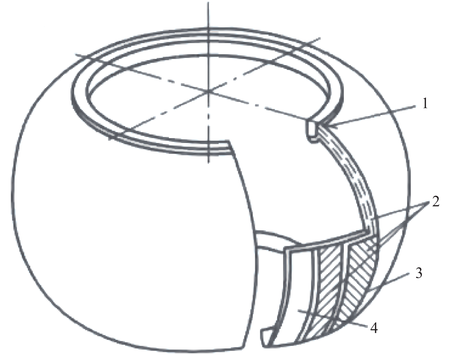
空簧气囊结构一般如图1所示,通过钢丝圈紧箍密闭,以中心帘线-橡胶层为主要承力部位,内外涂以胶层。常用于乘用车的空簧一般为膜式空簧,活塞上下移动时通过气囊壁垂耳在活塞边缘翻卷以改变空簧高度。一般来说,空簧有效面积Aeff与其高度和内部压强相关:
Aeff=Aeff1(p)+Aeff2(H) (1) 式中:p为气囊内部的相对压强;H为空簧气囊高度。
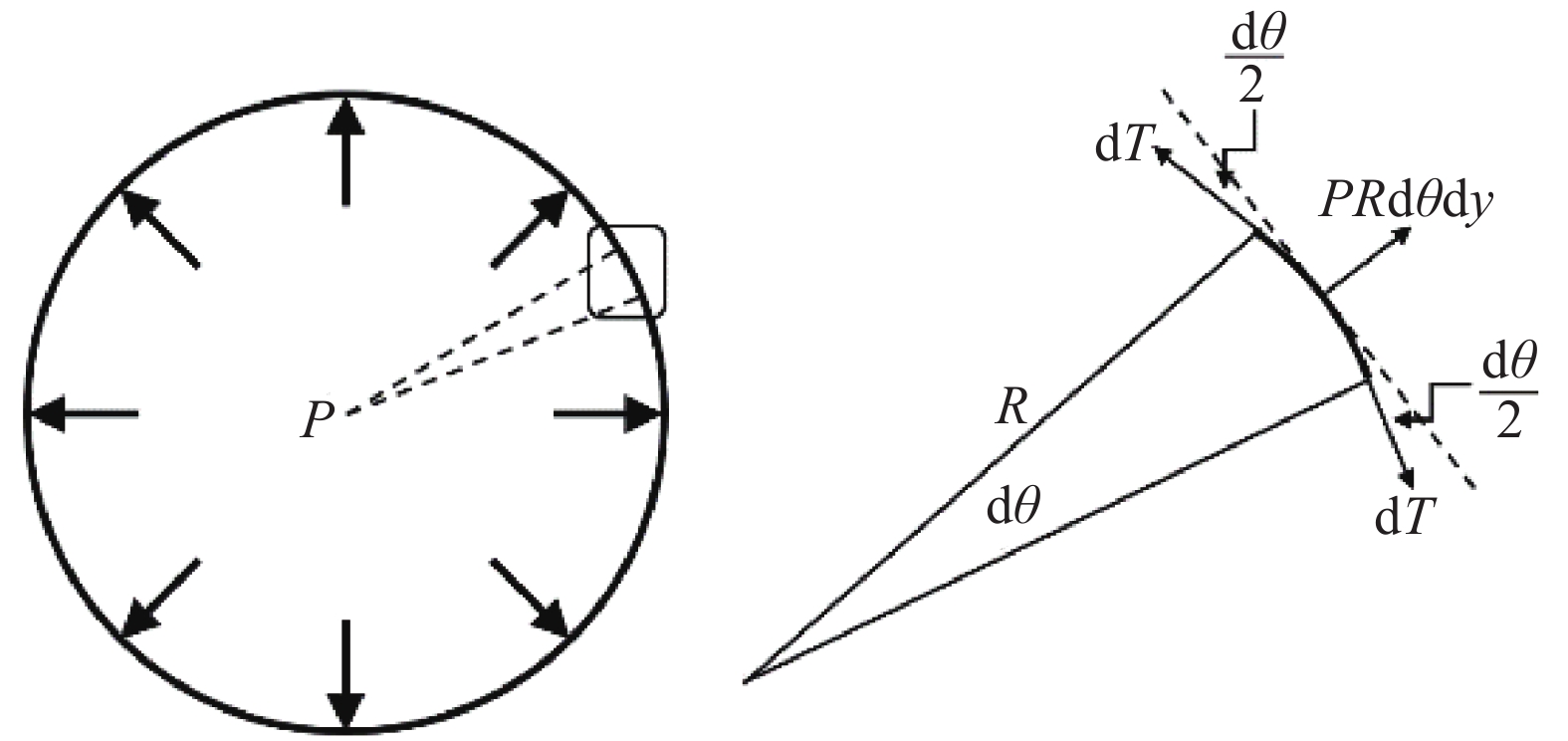
在气囊工作范围内可视其横截面为圆形,其纵截面如图2所示。这里取远离上下盖板及垂耳处、高度为dy的微元高度横切气囊壁进行分析,横切气囊壁微元段在径向和周向的受力情况如图3、图4所示。
在图3中,dθ为横切气囊壁微元段沿经线方向分割后对应的微元圆心角。由受力平衡,有:
pdA=pdyRdθ=2dTsindθ2=dTdθ (2) 式中:dA为微元面积;R为横切面的半径;dT为垂向的微元力。假定横切面在垂向上受到的与有效面积相关的拉力F0为
F0=δpπReff2 (3) 式中:δ为形状参数;Reff为有效面积对应的半径。
进一步进行经线方向和纬线方向的受力分析:
{dT=pRdy=TdydF=F02πRRdθ=pδ2Reff2RRdθ=FRdθ (4) 式中:dF为周向的微元力;T、F分别为垂向与周向单位长度上产生的力。由于取的微元体很小,近似符合平面应力条件,可将圆柱坐标系转化为随体直角坐标系。在该直角坐标系中,忽略内外气压差对垂直于平面方向应变的影响,结合转换关系dx=Rdθ,该微元体在随体坐标系下平面内受力状态如图4所示。
下面对微元体的材料结构进行分析。忽略内外胶层对气囊力学特性的影响,假定完全由帘线-橡胶层承载气囊所受的力。橡胶在大变形情况下具有非线性力学特性,但考虑到气囊是帘线增强的复合材料结构,在力学分析时为简化起见用线弹性材料描述橡胶基体行为。基于此假设,将帘线-橡胶看作正交各向异性复合材料,其中,橡胶作为基体提供支撑,尼龙帘线作为增强体起主要承力作用。
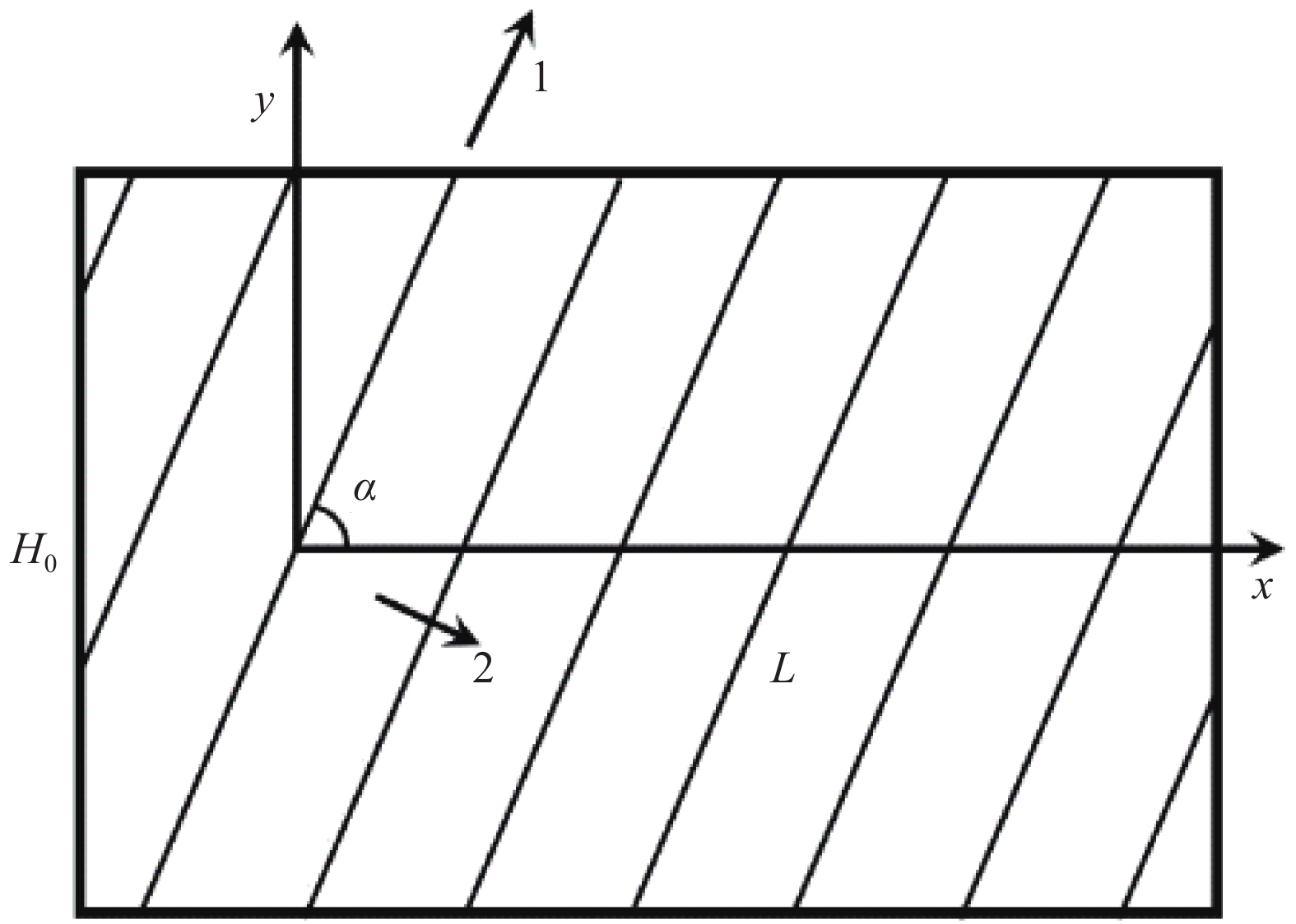
单层帘线-橡胶材料的帘线铺层随体坐标与主方向定义如图5所示。图中的x、y随体坐标轴方向分别对应于前述的空簧气囊的纬线方向与经线方向,1、2分别对应平行与垂直帘线的主方向。
结合上述假设,利用复合材料单层板理论[22],单层板1号主方向上的弹性模量E1、2号主方向的弹性模量E2、复合材料2-1方向泊松比ν21与1-2方向剪切模量G12的表达式分别为
E1=EfCf+Em(1−Cf) (5) E2=EfEmCmEf+CfEm (6) ν21=Cfνf+νm(1−Cf) (7) G12=GmGfGmCf+Gf(1−Cf) (8) 式中,Ef、Cf、νf和Gf分别表示帘线的弹性模量、相对体积含量、泊松比和剪切模量,与之相对应的m下标四个参量均为橡胶的等效材料参量。采用线弹性小变形的假设,存在如下关系[23]:
Em=9KG3K+G (9) 其中,K、G分别为橡胶材料等效的体积模量与剪切模量。值得注意的是,不同理论可对复合材料参数给予不同的预报,这里选择了较通用的一种,暂不研究参数预报方法的准确性。
根据前述假设得到的简化本构方程为
\left( {\begin{array}{*{20}{c}} {{\varepsilon _1}} \\ {{\varepsilon _2}} \\ {{\gamma _{12}}} \end{array}} \right)\; = \;{\boldsymbol{S}}\left( {\begin{array}{*{20}{c}} {{\sigma _1}} \\ {{\sigma _2}} \\ {{\tau _{12}}} \end{array}} \right)\; = \;\left( {\begin{array}{*{20}{c}} {{S_{11}}}&{{S_{12}}}&0 \\ {{S_{21}}}&{{S_{22}}}&0 \\ 0&0&{{S_{66}}} \end{array}} \right)\left( {\begin{array}{*{20}{c}} {{\sigma _1}} \\ {{\sigma _2}} \\ {{\tau _{12}}} \end{array}} \right)\; (10) 其中:σ1、ε1、σ2、ε2、γ12与τ12分别为面内1方向、2方向和1-2切向的应力与应变;S为柔度矩阵。进一步利用折减刚度矩阵Q表示本构方程:
\begin{split} &\left( {\begin{array}{*{20}{c}} {{\sigma _1}} \\ {{\sigma _2}} \\ {{\tau _{12}}} \end{array}} \right)\; = \;{\boldsymbol{Q}}\left( {\begin{array}{*{20}{c}} {{\varepsilon _1}} \\ {{\varepsilon _2}} \\ {{\gamma _{12}}} \end{array}} \right)\; =\\ &\;\left( {\begin{array}{*{20}{c}} {{Q_{11}}}&{{Q_{12}}}&0 \\ {{Q_{21}}}&{{Q_{22}}}&0 \\ 0&0&{{Q_{66}}} \end{array}} \right)\left( {\begin{array}{*{20}{c}} {{\varepsilon _1}} \\ {{\varepsilon _2}} \\ {{\gamma _{12}}} \end{array}} \right)\; = \;{{\boldsymbol{S}}^{ - 1}}\left( {\begin{array}{*{20}{c}} {{\varepsilon _1}} \\ {{\varepsilon _2}} \\ {{\gamma _{12}}} \end{array}} \right) \end{split} (11) 其中:
\begin{split} &{Q_{11}}\; = \;\frac{{{E_1}}}{{1\; - \;{\nu _{21}}{\nu _{12}}}},\;\;{Q_{12}}\; = \;{\nu _{12}}{Q_{11}},\\ &{Q_{22}}\; = \;\frac{{{E_2}}}{{1\; - \;{\nu _{21}}{\nu _{12}}}},\;\;{Q_{66}}\; = \;{G_{12}} \end{split} (12) 本构方程(11)中存在的四个独立的弹性常数,可利用前述预报公式求得,式(12)中1-2方向的泊松比ν12利用麦克斯韦方程式计算。进一步结合转移矩阵T进行复合材料的转轴转化:
\begin{split} & {\boldsymbol{T}}{\left( {\begin{array}{*{20}{c}} {{\sigma _x}}&{{\sigma _y}}&{{\tau _{xy}}} \end{array}} \right)^{\rm{T}}}\; = \;{\left( {\begin{array}{*{20}{c}} {{\sigma _1}}&{{\sigma _2}}&{{\tau _{12}}} \end{array}} \right)^{\rm{T}}} \\ & {\boldsymbol{T}}{\left( {\begin{array}{*{20}{c}} {{\varepsilon _x}}&{{\varepsilon _y}}&{\dfrac{1}{2}{\gamma _{xy}}} \end{array}} \right)^{\rm{T}}}\; = \;{\left( {\begin{array}{*{20}{c}} {{\varepsilon _1}}&{{\varepsilon _2}}&{\dfrac{1}{2}{\gamma _{12}}} \end{array}} \right)^{\rm{T}}} \end{split} (13) \left( {\begin{array}{*{20}{c}} {\begin{array}{*{20}{c}} {{\sigma _x}} \\ {{\sigma _y}} \end{array}} \\ {{\tau _{xy}}} \end{array}} \right) = \;{{\boldsymbol{T}}^{ - 1}}{\boldsymbol{Q}}{({{\boldsymbol{T}}^{ - 1}})^{\rm{T}}}\left( {\begin{array}{*{20}{c}} {\begin{array}{*{20}{c}} {{\varepsilon _x}} \\ {{\varepsilon _y}} \end{array}} \\ {{\gamma _{xy}}} \end{array}} \right) = \;{\boldsymbol{\bar Q}}\left( {\begin{array}{*{20}{c}} {\begin{array}{*{20}{c}} {{\varepsilon _x}} \\ {{\varepsilon _y}} \end{array}} \\ {{\gamma _{xy}}} \end{array}} \right) (14) 式中:σx、εx、σy、εy、γxy与τxy分别为面内x方向、y方向和x-y切向的应力与应变;
\bar{\boldsymbol{Q}} 为转轴折减刚度矩阵。下面对多层帘线-橡胶增强复合材料特性进行分析。当前用于乘用车的空簧帘线铺层一般采用偶数反对称铺设,帘线角度铺设形式类似于[+α/…/−α/+α/…/−α],α为正值帘线铺层角。图6为四层反对称层合板的示意,t为总厚度。根据复合材料宏观力学理论[22],层合板边缘单位长度受力向量N为
{\boldsymbol{N}}\; = \;\int_{ - \frac{t}{2}}^{\frac{t}{2}} {{\boldsymbol{\sigma }}{\rm{d}}z} \; = \;{\boldsymbol{A}}{{\boldsymbol{\varepsilon }}^0}\; + \;{\boldsymbol{BK}} (15) \begin{split} & {\boldsymbol{A}}\; = \;\displaystyle\sum\limits_{k\; = \;1}^n {{{{\boldsymbol{\bar Q}}}_k}({z_k}\; - \;{z_{k - 1}})} ,\;\;{\boldsymbol{B}}\; = \;\dfrac{1}{2}\displaystyle\sum\limits_{k\; = \;1}^n {{{{\boldsymbol{\bar Q}}}_k}({z_k}^2\; - \;{z_{k - 1}}^2)} \\ & {{\boldsymbol{\varepsilon }}^0}\; = \;{\left( {\begin{array}{*{20}{c}} {\varepsilon _x^0}&{\varepsilon _y^0}&{\gamma _{xy}^0} \end{array}} \right)^{\rm{T}}},\;\;{\boldsymbol{K}}\; = \;{\left( {\begin{array}{*{20}{c}} {{K_x}}&{{K_y}}&{{K_{xy}}} \end{array}} \right)^{\rm{T}}} \end{split} (16) 其中:A、B分别为拉伸、耦合刚度矩阵;ε0、K分别为中面应变向量、中面曲率向量;
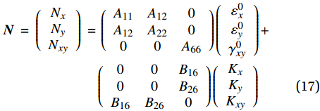
\bar{\boldsymbol{Q}} k为第k层的转轴折减刚度矩阵。偶数层反对称层合板的A、B矩阵有恒零项,且存在拉扭耦合。进一步将式(15)中A、B展开,写为\begin{split} {\boldsymbol{N}}\; = \;\left( {\begin{array}{*{20}{c}} {{N_x}} \\ {{N_y}} \\ {{N_{xy}}} \end{array}} \right)\; = &\;\left( {\begin{array}{*{20}{c}} {{A_{11}}}&{{A_{12}}}&0 \\ {{A_{12}}}&{{A_{22}}}&0 \\ 0&0&{{A_{66}}} \end{array}} \right)\left( {\begin{array}{*{20}{c}} {\varepsilon _x^0} \\ {\varepsilon _y^0} \\ {\gamma _{xy}^0} \end{array}} \right) + \\ &\left( {\begin{array}{*{20}{c}} 0&0&{{B_{16}}} \\ 0&0&{{B_{26}}} \\ {{B_{16}}}&{{B_{26}}}&0 \end{array}} \right)\left( {\begin{array}{*{20}{c}} {{K_x}} \\ {{K_y}} \\ {{K_{xy}}} \end{array}} \right) \end{split} (17) 考虑到本文主要关注气囊x、y方向上的宏观作用力产生的应变,忽略层合板的扭曲率,即Kxy = 0,结合式(4),简化式(17)为
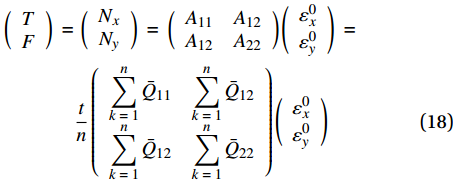
\begin{split} \left( {\begin{array}{*{20}{c}} T \\ F \end{array}} \right)\; =& \;\left( {\begin{array}{*{20}{c}} {{N_x}} \\ {{N_y}} \end{array}} \right)\; = \;\left( {\begin{array}{*{20}{c}} {{A_{11}}}&{{A_{12}}} \\ {{A_{12}}}&{{A_{22}}} \end{array}} \right)\left( {\begin{array}{*{20}{c}} {\varepsilon _x^0} \\ {\varepsilon _y^0} \end{array}} \right)\; = \\ &\frac{t}{n}\left( {\begin{array}{*{20}{c}} {\displaystyle\sum\limits_{k\; = \;1}^n {{{\bar Q}_{11}}} }&{\displaystyle\sum\limits_{k\; = \;1}^n {{{\bar Q}_{12}}} } \\ {\displaystyle\sum\limits_{k\; = \;1}^n {{{\bar Q}_{12}}} }&{\displaystyle\sum\limits_{k\; = \;1}^n {{{\bar Q}_{22}}} } \end{array}} \right)\left( {\begin{array}{*{20}{c}} {\varepsilon _x^0} \\ {\varepsilon _y^0} \end{array}} \right) \end{split} (18) 其中,n为层数。由上文的简化可见,拉扭耦合矩阵B对有效面积计算没有影响。结合层合板的反对称性,式(18)进一步可以简化为
\begin{split} \left( {\begin{array}{*{20}{c}} T \\ F \end{array}} \right)\; = &\;\frac{t}{n} \times n\left( {\begin{array}{*{20}{c}} {{{\bar Q}_{11}}}&{{{\bar Q}_{12}}} \\ {{{\bar Q}_{12}}}&{{{\bar Q}_{22}}} \end{array}} \right)\left( {\begin{array}{*{20}{c}} {\varepsilon _x^0} \\ {\varepsilon _y^0} \end{array}} \right)\; = \\ &t\left( {\begin{array}{*{20}{c}} {{{\bar Q}_{11}}}&{{{\bar Q}_{12}}} \\ {{{\bar Q}_{12}}}&{{{\bar Q}_{22}}} \end{array}} \right)\left( {\begin{array}{*{20}{c}} {\varepsilon _x^0} \\ {\varepsilon _y^0} \end{array}} \right) \end{split} (19) 注意到转轴折减刚度矩阵中并非所有项都需要经过计算得出,可得
{\bar{\boldsymbol{Q}}}_{k} 部分项的表达式为\left( {\begin{array}{*{20}{c}} {{{\bar Q}_{{\rm{11}}}}} \\ {{{\bar Q}_{{\rm{22}}}}} \\ {{{\bar Q}_{{\rm{12}}}}} \end{array}} \right)\;{\rm{ = }}\;\left( {\begin{array}{*{20}{l}} {{{\cos }^4}\alpha }&{{{\sin }^4}\alpha }&{2{{\cos }^2}\alpha {{\sin }^2}\alpha }&{4{{\cos }^2}\alpha {{\sin }^2}\alpha } \\ {{{\sin }^4}\alpha }&{{{\cos }^4}\alpha }&{2{{\cos }^2}\alpha {{\sin }^2}\alpha }&{4{{\cos }^2}\alpha {{\sin }^2}\alpha } \\ {{{\cos }^2}\alpha {{\sin }^2}\alpha }&{{{\cos }^2}\alpha {{\sin }^2}\alpha }&{{{\sin }^4}\alpha \; + \;{{\cos }^4}\alpha }&{ - 4{{\cos }^2}\alpha {{\sin }^2}\alpha } \end{array}} \right)\left( {\begin{array}{*{20}{c}} {{Q_{11}}} \\ {{Q_{22}}} \\ {{Q_{12}}} \\ {{Q_{66}}} \end{array}} \right) (20) 对微元体受力平衡方程式(4)进行转化:
\left\{ \begin{array}{l} T\; = \;pR \\ F\; = \;\dfrac{{p\delta }}{2}\dfrac{{{R_{{\rm{eff}}}}^2}}{R}\; = \;p{R_\delta },\;\;\;{R_\delta }{\rm{ = }}\dfrac{\delta }{2}\dfrac{{{R_{{\rm{eff}}}}^2}}{R} \\ \end{array} \right. (21) 由(19)可得:
\left( {\begin{array}{*{20}{c}} {\varepsilon _x^0} \\ {\varepsilon _y^0} \end{array}} \right)\; = \;\dfrac{p}{t}{{\boldsymbol{Q}}_{\boldsymbol{0}}}\left( {\begin{array}{*{20}{c}} R \\ {{R_\delta }} \end{array}} \right)\; = \;\dfrac{p}{t}{\left( {\begin{array}{*{20}{c}} {{{\bar Q}_{11}}}&{{{\bar Q}_{12}}} \\ {{{\bar Q}_{12}}}&{{{\bar Q}_{22}}} \end{array}} \right)^{ - 1}}\left( {\begin{array}{*{20}{c}} R \\ {{R_\delta }} \end{array}} \right) (22) 此处主要关心
\varepsilon _x^0 ,即与气囊半径变化相关的中面横向应变:\varepsilon _x^0\; = \;\frac{{R - {R_{\rm{D}}}}}{{{R_{\rm{D}}}}}\; = \;\frac{p}{t}({Q_1}R\; + \;{Q_2}{R_\delta }) (23) 其中:Q1、Q2为式(22)中定义的Q0矩阵第一行第一列和第二列的元素,材料特性确定后,为α的函数,且有Q1 > 0、Q2 < 0;R为压强变化后的气囊半径;RD为气囊内压强较小时,随压强变化不再发生明显径向形变的初始半径,经实验确定为内部相对压强为0.2 MPa时的气囊外半径。式(23)进一步转化为
\frac{{R - {R_D}}}{{{R_D}}}\; = \;\frac{p}{t}\left({Q_1}R\; + \;{Q_2}\frac{{\delta {R_{{\rm{eff}}}}^2}}{{2R}}\right) (24) 根据式(24)可得有效面积随压强变化部分的表达式为
{A_{{\rm{eff1}}}}\; = \;{\rm{{\text{π}} }}{R_{{\rm{eff}}}}^2\; = \;\frac{{{Q_1}}}{{ - {Q_2}}}\frac{{2{\rm{{\text{π}} }}{R^2}}}{\delta }\; - \;\frac{1}{{ - {Q_2}}}\frac{{2{\rm{{\text{π}} }}R(R - {R_{\rm{D}}})t}}{{{R_{\rm{D}}}\delta p}} (25) 这里假设空簧气囊壁在经线方向长度不变,铺层角α不随空簧高度发生变化[13]。引入新的参数λ、β,并将式(25)进行转化:
\begin{split} &\lambda \; = \;\dfrac{{2{\rm{{\text{π}} }}{R^2}}}{\delta },\;\;\beta \; = \;\dfrac{{2{\rm{{\text{π}} }}R(R - {R_{\rm{D}}})t}}{{{R_{\rm{D}}}\delta }} \\ & {A_{{\rm{eff1}}}}\; = \;\dfrac{{{Q_1}}}{{ - {Q_2}}}\lambda \; - \;\dfrac{1}{{ - {Q_2}}}\beta \dfrac{1}{p} \end{split} (26) 空簧气囊的高度主要由气囊壁垂耳的翻卷改变,前述分析没有考虑到这一高度变化的影响。基于实验[19]与几何图解[3]的方法均指出有效面积随高度的近似线性变化规律。这里设定高度对有效面积的影响为线性,由根据实验确定的参量κ表征[20]。这一部分对有效面积的影响写为
{A_{{\rm{eff2}}}}\; = \;\kappa (H - {H_0}) (27) 其中,H0为实验中空簧的初始工作高度。结合式(26)~(27),进一步定义参数Δ:
\varDelta \; = \; - \kappa {H_0} + \frac{{{Q_1}}}{{ - {Q_2}}}\lambda (28) 最终有效面积预测公式写为
{A_{{\rm{eff}}}}\; = \;\kappa H + \varDelta - \;\frac{1}{{ - {Q_2}}}\beta \lambda \frac{1}{p} (29) 根据相应国家标准GB/T 9101—2017[24],采用的帘线-橡胶力学参数[25-26]如表1所示。根据式(5)~(8)计算出的复合材料表观力学参数如表2所示,参数Q1、Q2随铺层角α的变化规律如图7所示。
表 1 橡胶和帘线力学参数Table 1. Mechanical parameters of rubber and cordParameter Value Ef/MPa 2700 νf 0.3 Cf/% 33.2 Gf/MPa 1038 Em/MPa 2.0 νm 0.497 Cm/% 66.8 Gm/MPa 0.667 Notes: Ef, νf, Cf and Gf —Young’s modulus, Poisson’s ratio, volume fraction and shear modulus of cord material in composite; Em, νm, Cm and Gm—Equivalent Young’s modulus, Poisson’s ratio, volume fraction and shear modulus of rubber material in composite. 表 2 计算得到的帘线-橡胶复合材料表观力学值Table 2. Apparent mechanical value of cord-rubber composite via computationParameter Value E1/MPa 897.7 E2/MPa 2.993 ν21 0.432 ν12 1.439×10⁻³ G12/MPa 0.998 Q11/MPa 898.3 Q12/MPa 1.293 Q22/MPa 2.995 Q66/MPa 0.998 Notes: E1, E2—Elastic modulus of laminate in 1st and 2nd principle direction; ν21, ν12—Poisson’s ratios of laminate; G12—Shear modulus of laminate in plane; Q11, Q12, Q21, Q22 and Q66—Elements in matrix Q in Eq.(11). 2. 实验对比与验证
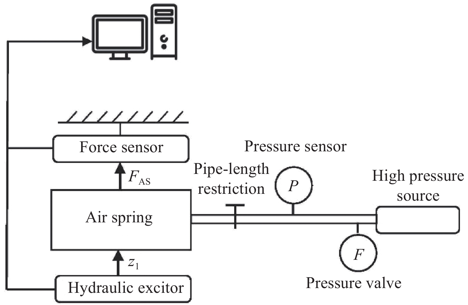
在上述理论分析基础上,利用Mechanical Testing & Simulation公司生产的力学性能测试平台对某型号后空簧进行了实验,图8和图9分别为实验台架设备及实验原理。台架下端的液压作动器可产生给定位移,台架上端的力传感器可以测量产生的力并传输至计算机进行采集分析。
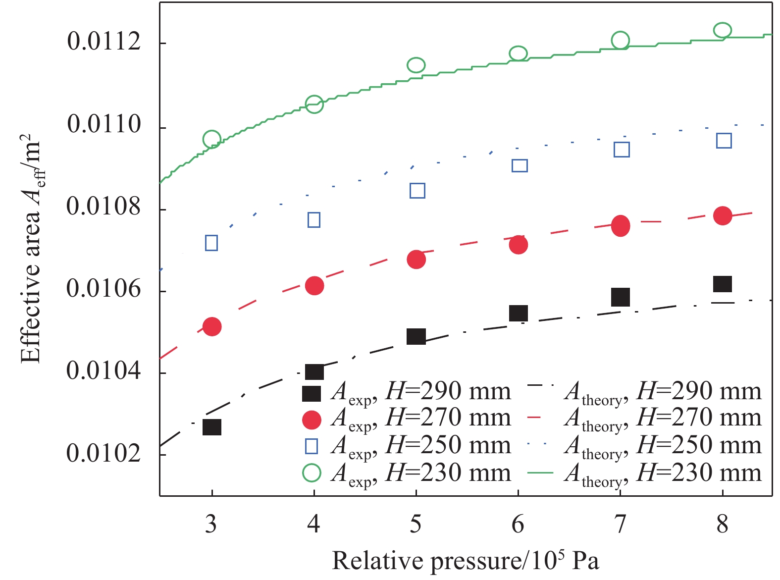
在实验中,首先将空簧上端固定,调节下端位置到一定高度并充气至较低的初始压强。保持空簧高度不变,利用减压阀改变空簧内的气体压强,其值通过与管路相连的压强传感器读出。在不同压强下,当力传感器、压强传感器测得的数据基本保持稳定时,记录对应的力与压强。在同一高度下完成不同充气压强的实验测量后,再调整台架至另一实验高度,重复上述过程。最终根据测得的力与压强的比值作为各测量工况下的有效面积。为保证数据的准确性,同一高度的实验中先逐步升压至最大测量压强,再逐步减压至初始压强,每一个压强测量点在升降压过程中均进行数据采集并求平均以减小误差。实验选择了230 mm、250 mm、270 mm和290 mm的空簧高度进行实验,压强变化范围为0.3~0.8 MPa,这基本覆盖了该空簧的实际工况。
根据上节所述的理论分析方法,结合空簧的基本参数,对该空簧的有效面积计算公式进行了拟合,部分参数取值如表3所示,实验数据与理论预测数据如图10所示,理论与实验的误差情况如表4所示。由图10可知,随高度减小、压强增大,有效面积有变大的趋势,此时经线方向上卷耳部分的长度增加,导致空簧气囊整体有变得矮粗的趋势。由表4可以看出,在实验对应的测量范围中,理论预测的有效面积误差都小于1%,这表明上述空簧有效面积的理论分析方法能很好地与实验数据相符合,对进行空簧有效面积的预测具有一定的指导意义。
表 3 用于空气弹簧有效面积计算的参数取值Table 3. Parameter values in effective area computation for air springParameter Value α/(°) 50 R/10−2m 7.50 RD /10−2m 7.32 t/10−3m 2.00 δ 0.8 κ/10−2m −1.069 Δ/m2 0.01383 Notes: R—Bellow radius after pressure variation; RD —Initial bellow radius without obvious radial deformation; δ, κ and Δ—Experimental parameters defined in Eq.(27) and Eq.(29). 表 4 空气弹簧理论预测与实验数据的误差Table 4. Errors between experimental data and theoretical prediction of air springPressure/
105 Pae23/% e25/% e27/% e29/% 3 0.20 0.11 <0.01 0.39 4 0.04 0.56 0.11 0.03 5 0.31 0.51 0.10 0.16 6 0.18 0.35 0.14 0.29 7 0.22 0.25 <0.01 0.38 8 0.23 0.26 <0.01 0.46 Notes: e23, e25, e27 and e29—Errors between experimental data and theoretical prediction when height of air spring are 230 mm, 250 mm, 270 mm and 290 mm, respectively. 3. 结 论
(1) 提出一种车用膜式空簧的有效面积理论分析与预测方法,给出了与空簧高度和内部压强相关的空簧有效面积理论预测表达式。
(2) 利用实验台架对某型号空簧进行有效面积测量实验,实验与理论预测的结果的对比验证了这种理论分析方法的合理性。
-
表 1 实验材料的相关参数
Table 1 Related parameters of experimental materials
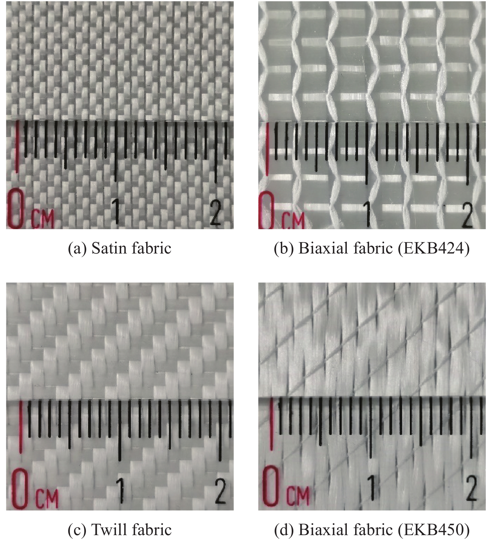
Material Type Areal weight/(g·m−2) Density/(kg·m−3) Vinyl resin ATLAC 430 LV − 1100 Satin fabric − 220 2550 Twill fabric 2/2 Twill 327 2550 Biaxial fabric EKB450 455 2550 Biaxial fabric EKB424 424 2550 表 2 纤维织物的面内渗透率结果
Table 2 In-plane permeability results of fiber fabric
Textile α/(°) K45°/10−11 m2 K1/10−11 m2 K2/10−11 m2 β SF 86 2.386 2.565 2.230 0.869 Twill 78 0.521 0.662 0.430 0.649 EKB450 74 0.990 1.387 0.769 0.554 EKB424 58 9.544 25.442 5.874 0.231 Notes: K45°—Permeability of the fabric in 45° direction; K1—Permeability of the fabric in the fastest direction; K2—Permeability of fabric in the slowest direction; β—Degree of anisotropy. 表 3 SF在均一铺层与阶梯铺层下渗透率对比
Table 3 Comparison of permeability of SF under uniform ply and step ply
Textile Number of
layersThickness/
mmAverage layer
thickness/mmVf/% KU/(10−11 m2) σ/(10−11 m2) KS/(10−11 m2) σ/(10−11 m2) SF 2 0.331 0.1655 52.13 2.490 0.451 4.363 0.829 3 0.525 0.1750 49.30 2.613 0.424 3.586 0.663 4 0.723 0.1808 47.73 2.691 0.487 2.998 0.874 5 0.922 0.1844 46.79 2.773 0.513 2.775 0.730 Notes: Vf—Fiber volume fraction; KU—Permeability under uniform ply; KS—Permeability under step ply; σ—Standard deviation. -
[1] 武卫莉, 陈丰雨. 真空辅助树脂灌注法制备风电叶片树脂的渗透及缺陷[J]. 复合材料学报, 2019, 36(12):2779-2785. WU Weili, CHEN Fengyu. Resin permeation and defects of wind turbine blades prepared by vacuum assisted resin infusion method[J]. Acta Materiae Compositae Sinica,2019,36(12):2779-2785(in Chinese).
[2] 赵安安, 王林文, 王浩军, 等. 复合材料液体成型技术的航空应用[J]. 工程塑料应用, 2018, 46(4):145-150. ZHAO Anan, WANG Linwen, WANG Haojun, et al. Application of liquid composite molding technology on aeronautics[J]. Engineering Plastics Applications,2018,46(4):145-150(in Chinese).
[3] KONSTANTOPOULOS S, HUEBER C, ANTONIADIS I, et al. Liquid composite molding reproducibility in real-world production of fiber reinforced polymeric composites: A review of challenges and solutions[J]. Advanced Manufacturing: Polymer & Composites Science,2019,5(3):85-99.
[4] 杨旭静, 王跃飞, 韦凯, 等. 基于孔隙控制的车身结构树脂传递模塑成型工艺设计[J]. 复合材料学报, 2017, 34(5):970-977. YANG Xujing, WANG Yuefei, WEI Kai, et al. Design of resin transfer molding process for vehicle body structure based on porosity control[J]. Acta Materiae Compositae Sinica,2017,34(5):970-977(in Chinese).
[5] SIRTAUTAS J, PICKETT A K, GEORGE A. Materials characterisation and analysis for flow simulation of liquid resin infusion[J]. Applied Composite Materials,2014,22(3):1-19.
[6] NAIK N K, SIRISHA M, INANI A. Permeability characterization of polymer matrix composites by RTM/VARTM[J]. Progress in Aerospace Sciences, 2014, 65: 22-40.
[7] MAY D, AKTAS A, ADVANI S G, et al. In-plane permeability characterization of engineering textiles based on radial flow experiments: A benchmark exercise[J]. Composites Part A: Applied Science and Manufacturing,2019,121:100-114. DOI: 10.1016/j.compositesa.2019.03.006
[8] RUIZ E, VERNET N, ADVANI S. Experimental determination of the permeability of engineering textiles: Benchmark II[J]. Composites Part A: Applied Science and Manufacturing,2014,61:172-184. DOI: 10.1016/j.compositesa.2014.02.010
[9] DEMARIA C, RUIZ E, TROCHU F. In-plane anisotropic permeability characterization of deformed woven fabrics by unidirectional injection. Part I: Experimental results[J]. Polymer Composites,2007,28(6):797-811. DOI: 10.1002/pc.20107
[10] FAUSTER E, BERG D C, MAY D, et al. Robust evaluation of flow front data for in-plane permeability characterization by radial flow experiments[J]. Advanced Manufacturing: Polymer & Composites Science,2018,4(1):24-40.
[11] 张嘉阳, 刘刚, 李龙, 等. 国产CCF300碳纤维单向织物液体成型工艺性及其复合材料力学性能[J]. 复合材料学报, 2016, 33(1):17-26. ZHANG Jiayang, LIU Gang, LI Long, et al. Processability of domestic CCF300 carbon fiber unidirectional fabrics for liquid molding and mechanical properties of their compo-sites[J]. Acta Materiae Compositae Sinica,2016,33(1):17-26(in Chinese).
[12] FERLAND P, GUITTARD D, TROCHU F. Concurrent methods for permeability measurement in resin transfer molding[J]. Polymer Composites, 1996, 17(1): 149-158.
[13] PIERCE R S, FALZON B G, THOMPSON M C. Permeability characterization of sheared carbon fiber textile preform[J]. Polymer Composites,2018,39(7):2287-2298. DOI: 10.1002/pc.24206
[14] COSSON B. Optical measurement of local permeability of flax fiber fabrics before liquid composite molding[J]. Journal of Composite Materials,2018,52(24):3289-3297. DOI: 10.1177/0021998318764579
[15] 耿奕, 蒋金华, 陈南梁. 经编四轴向玻璃纤维织物的渗透行为和渗透率[J]. 纺织学报, 2017, 38(10):49-56. GENG Yi, JIANG Jinhua, CHEN Nanliang. Permeation behavior and permeability of warp-knitted quadri-axial glass fiber fabric[J]. Journal of Textile Research,2017,38(10):49-56(in Chinese).
[16] 方良超. 嵌套效应对织物压缩性及渗透性的影响研究[D]. 西安: 西北工业大学, 2016. FANG Liangchao. Effect of nesting on compaction and permeability properties of fabrics[D]. Xi’an: Northwestern Polytechnical University, 2016(in Chinese).
[17] PEARCE N, SUMMERSCALES J. The compressibility of a reinforcement fabric[J]. Composites Manufacturing,1995,6(1):15-21. DOI: 10.1016/0956-7143(95)93709-S
[18] 周莉莉. 实时监测技术在LCM工艺上的应用研究[D]. 上海: 东华大学, 2009. ZHOU Lili. Application of real-time sensing and monitoring in LCM process[D]. Shanghai: Donghua University, 2009(in Chinese).
[19] 武红玉. 阈值分割算法在图像处理中的应用[J]. 科技信息, 2012(27):201-202. WU Hongyu. Application of threshold segmentation algorithm in image processing[J]. Science and Technology Information,2012(27):201-202(in Chinese).
[20] 孔凡胜, 王竹林, 高伟伟. 某型检测系统图像信息噪声处理研究[J]. 计算机与数字工程, 2014, 42(8):1484-1487. KONG Fansheng, WANG Zhulin, GAO Weiwei. Noise information processing of some detection system[J]. Computer and Digital Engineering,2014,42(8):1484-1487(in Chinese).
[21] FRATTA C D, KOUTSOUKIS G, KLUNKER F, et al. Characterization of anisotropic permeability from flow front angle measurements[J]. Polymer Composites,2016,37(7):2037-2052. DOI: 10.1002/pc.23382
[22] BARIS C, DAMIANO S, MURAT S E, et al. In-plane permeability distribution mapping of isotropic mats using flow front detection[J]. 2018, 113: 275-286.
-
期刊类型引用(6)
1. 付硕,许一虎,孙治博. 汽车空气悬架系统及精准控制技术发展综述. 液压与气动. 2023(04): 107-114 .  百度学术
百度学术
2. 陈俊杰,谭月玲,康盛,邱光琦. 膜式空气弹簧帘子线铺设角-承载力映射模型研究. 振动与冲击. 2023(21): 291-297 .  百度学术
百度学术
3. 中国汽车工程学术研究综述·2023. 中国公路学报. 2023(11): 1-192 .  百度学术
百度学术
4. 王相平,李星,王剑锋,吴少培,丁旺才,李国芳. 中低速磁浮车辆空气弹簧动力学建模及其应用研究. 振动工程学报. 2023(06): 1527-1538 .  百度学术
百度学术
5. 刘琼,杨纪远,张磊,商涛,谢济兴. 帘线参数对单囊空气弹簧垂向刚度的影响研究. 三明学院学报. 2023(06): 117-124 .  百度学术
百度学术
6. 孙文,李晨阳,王军年,钱灏喆,张文通. 越野车复合型悬架平顺性的研究. 汽车工程. 2022(01): 105-114+122 .  百度学术
百度学术
其他类型引用(8)
-


 下载:
下载:


