


Online defect detection of composite material fiber placement based on 2.5D images
-
摘要: 复合材料自动铺丝技术(AFP)广泛应用于飞机壁板、机身段和发动机进气道等复杂构件的制造中,虽然铺丝过程已经高度自动化,但仍缺少与之匹配的在线缺陷检测手段。直接基于铺层表面2D图像的检测方法往往缺陷图像特征不明显,准确率不高。基于3D点云的检测方法标注与计算成本昂贵且实时性不高。为此,提出一种利用2.5D图像信息的缺陷检测方法。首先将线激光传感器与铺丝头固连,跟随铺丝过程实时采集铺层的轮廓信息;然后对每一条轮廓线进行滤波和基线漂移校正等预处理,将轮廓数据映射为2.5D图像;使用目前先进的深度学习目标检测技术,并提出一种新的目标检测后处理算法,用以归并与筛选图像中缺陷。以飞机进气道自动铺丝进行实验验证,本文方法可对间隙、搭接、三角区、翻折和夹杂等多种缺陷进行有效检测,总体误检率为7.3%,总体漏检率为4.1%。检测效率在GPU加速下可达143fps,将模型部署至CPU下为13fps,满足实时在线的检测要求。Abstract: Automatic fiber placement (AFP) technology is extensively applied in the manufacturing of complex components such as aircraft panels, fuselage sections, and engine inlets. Despite the high level of automation in the AFP process, there remains a significant gap in the availability of effective online defect detection methods. Traditional 2D image-based detection techniques often suffer from unclear defect features, leading to low accuracy, while 3D point cloud-based methods are costly in terms of both annotation and computation and often lack real-time processing capabilities. To address these challenges, this paper proposes a novel defect detection method leveraging 2.5D image information. A line laser sensor is rigidly attached to the AFP head to capture real-time contour information during the layup process. The collected contour data undergoes pre-processing steps, including filtering and baseline drift correction, before being transformed into a 2.5D image. Advanced deep learning-based object detection techniques are then employed, alongside a newly developed post-processing algorithm to accurately merge and filter defects within the images. Experimental validation conducted on an automated layup process for aircraft inlet ducts demonstrates the effectiveness of the proposed method in detecting various defects, such as gap, bridge, triangle, fold, and mix. The method achieves an overall false rate of 7.3% and miss rate of 4.1%. The detection efficiency reaches up to 143 frames per second (fps) with GPU acceleration and 13 fps on CPU, satisfying the real-time online detection requirements.
-
Key words:
- automatic fiber placement /
- defect detection /
- line laser /
- deep learning /
- YOLO
-
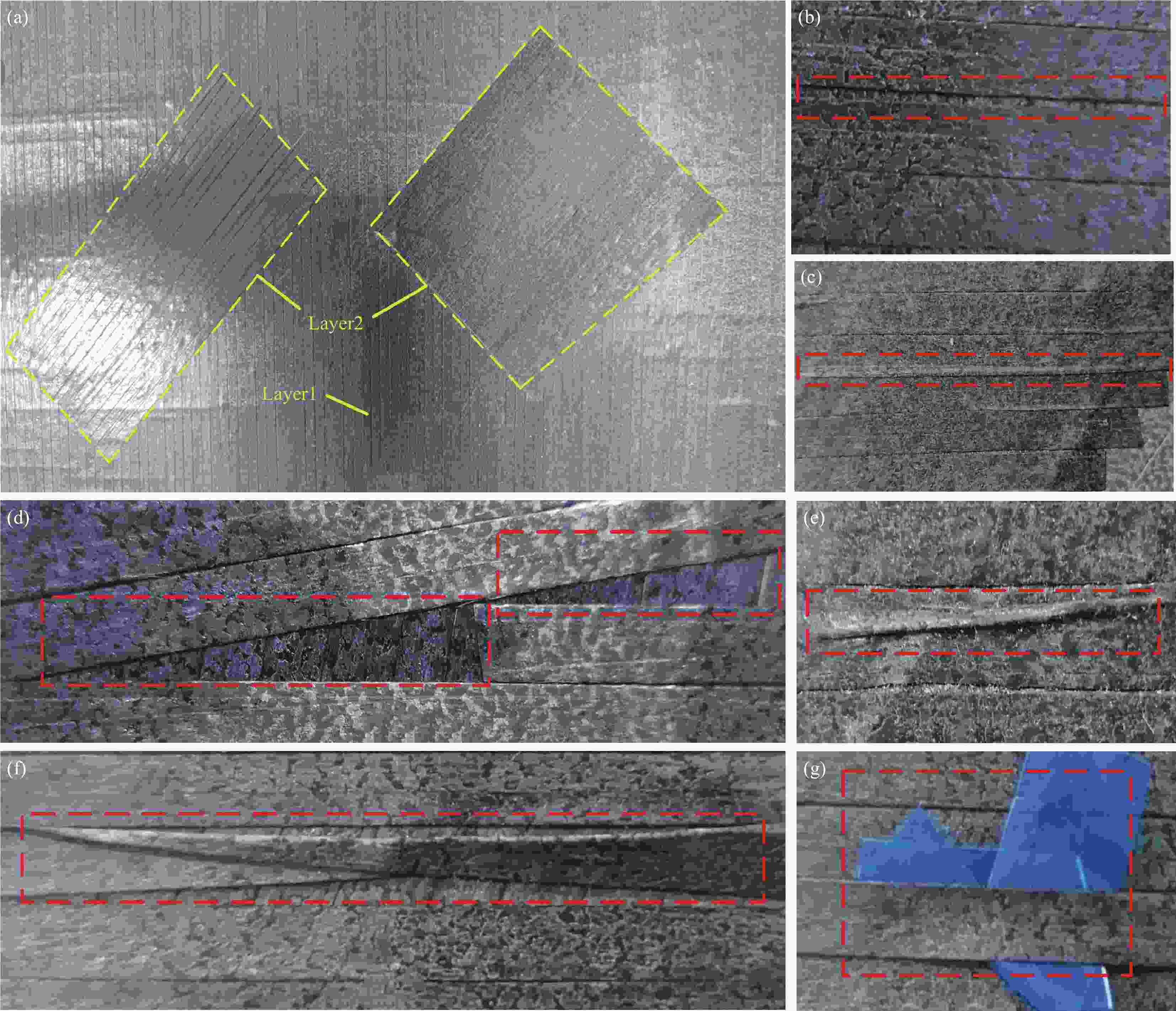
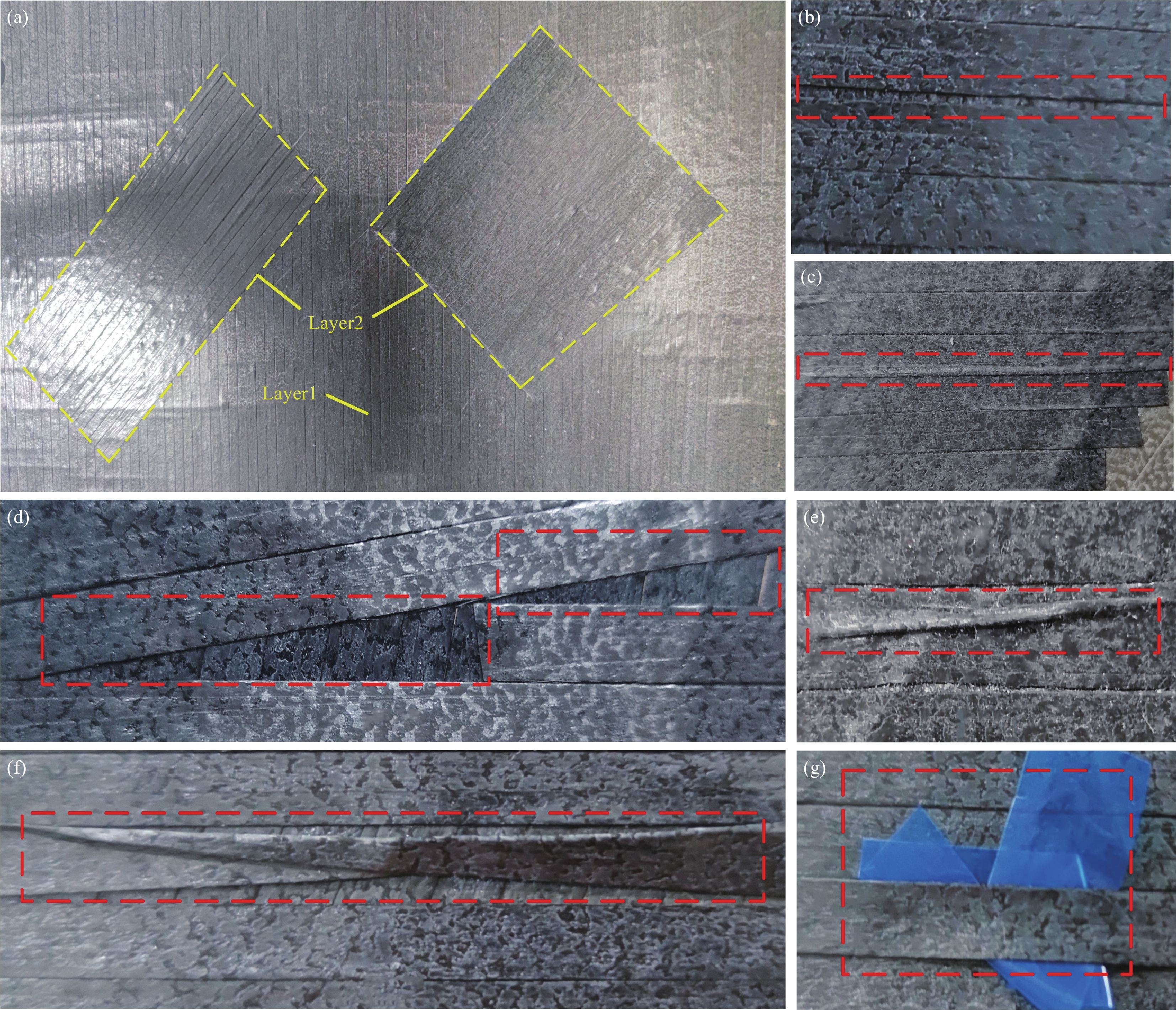
图 1 铺层与缺陷图片:(a)复合材料铺层;(b)间隙缺陷;(c)搭接缺陷;(d)三角区缺陷;(e)褶皱缺陷;(f)翻折缺陷;(g)由预浸丝背衬导致的夹杂缺陷
Figure 1. Layer and defects images: (a) Composite material layers; (b) Gap defect; (c) Bridge defect; (d) Triangle defects; (e) Wrinkle defect; (f) Fold defect; (g) Mix defect caused by backing paper of prepreg tape
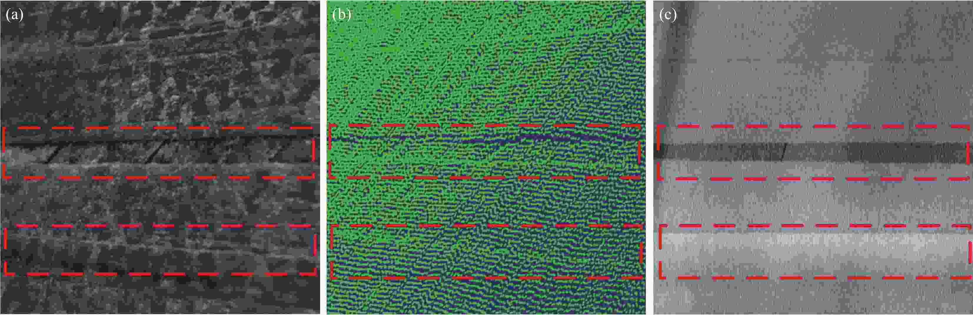
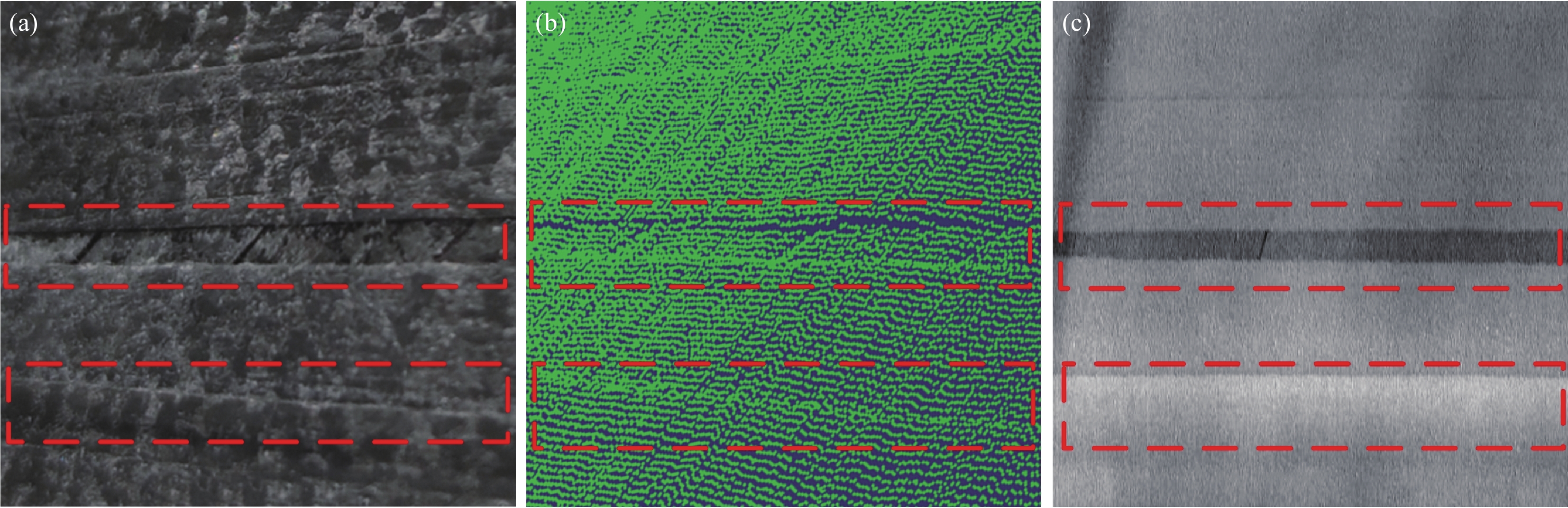
图 2 不同维度下的缺陷:(a) 2D图像;(b) 3D点云;(c) 2.5D高度映射图
Figure 2. Defects in different dimensions: (a) 2D image; (b) 3D point cloud; (c) 2.5D height mapping image
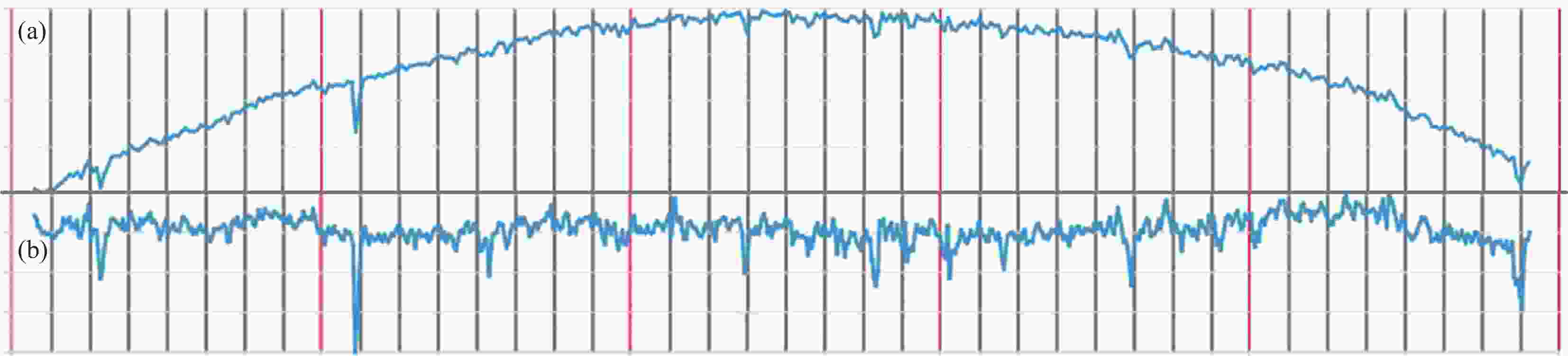
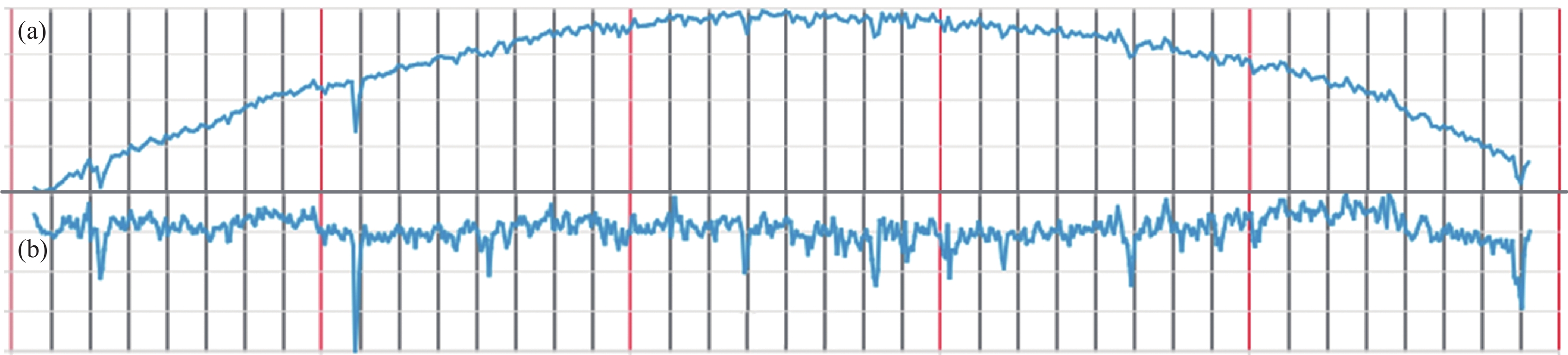
图 6 基线漂移校正:(a)校正前轮廓线;(b)校正后轮廓线
Figure 6. Baseline drift correction: (a) Contour line before correction; (b) Contour line after correction
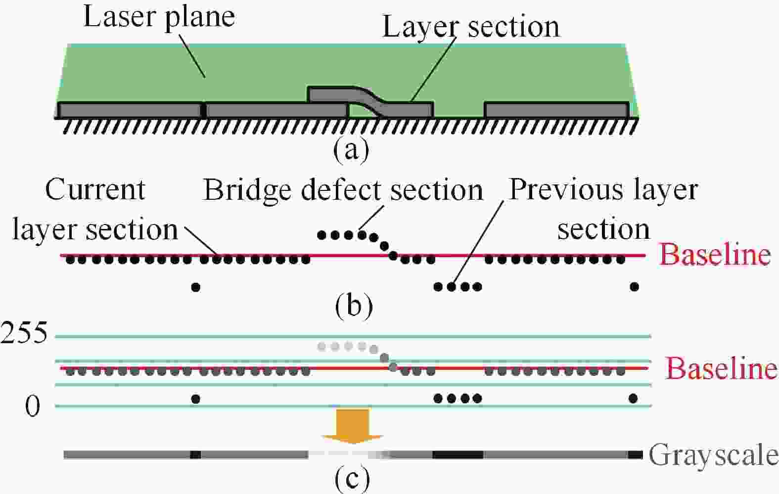
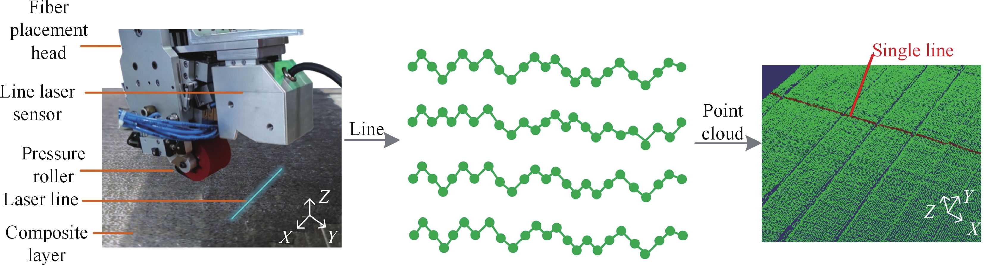
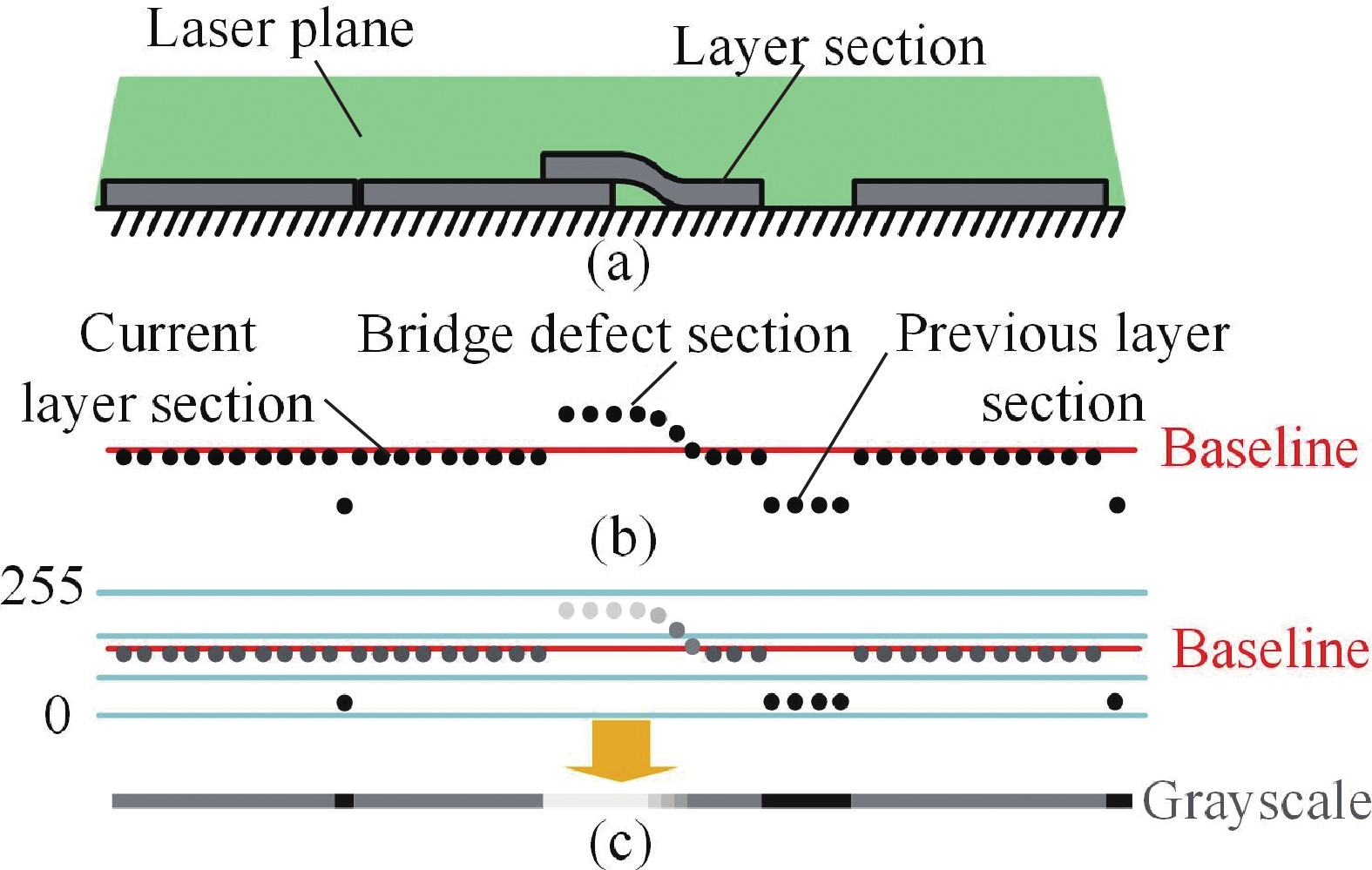
图 7 高度映射示意图:(a)传感器检测示意图;(b)铺层截面轮廓点示意图;(c)灰度映射示意图
Figure 7. Diagram of height mapping: (a) Diagram of sensor detection;(b) Diagram of the layer section profile points; (c) Diagram of grayscale mapping
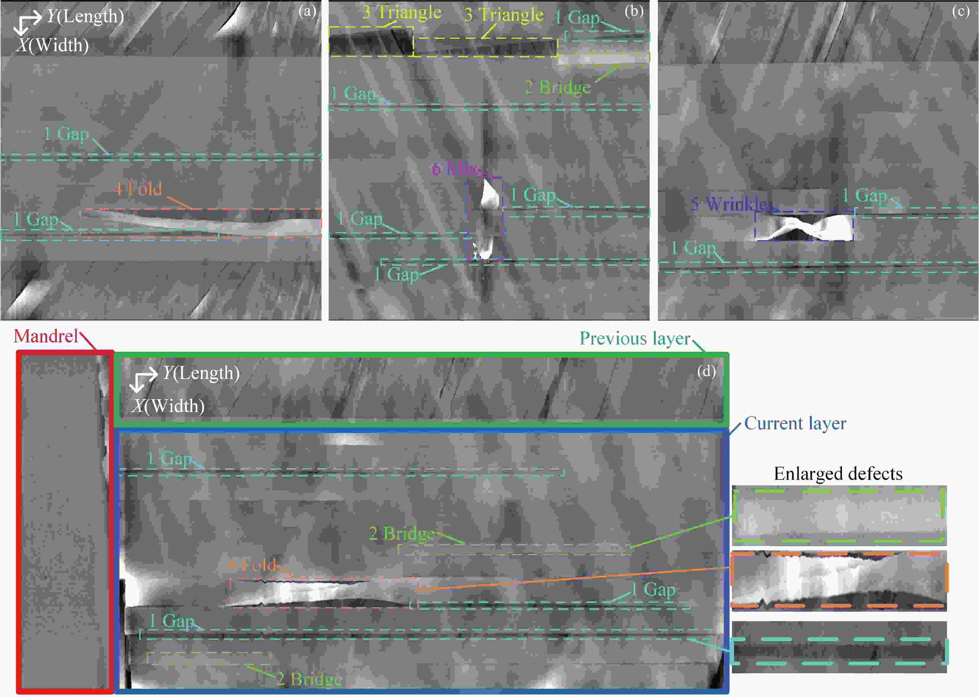
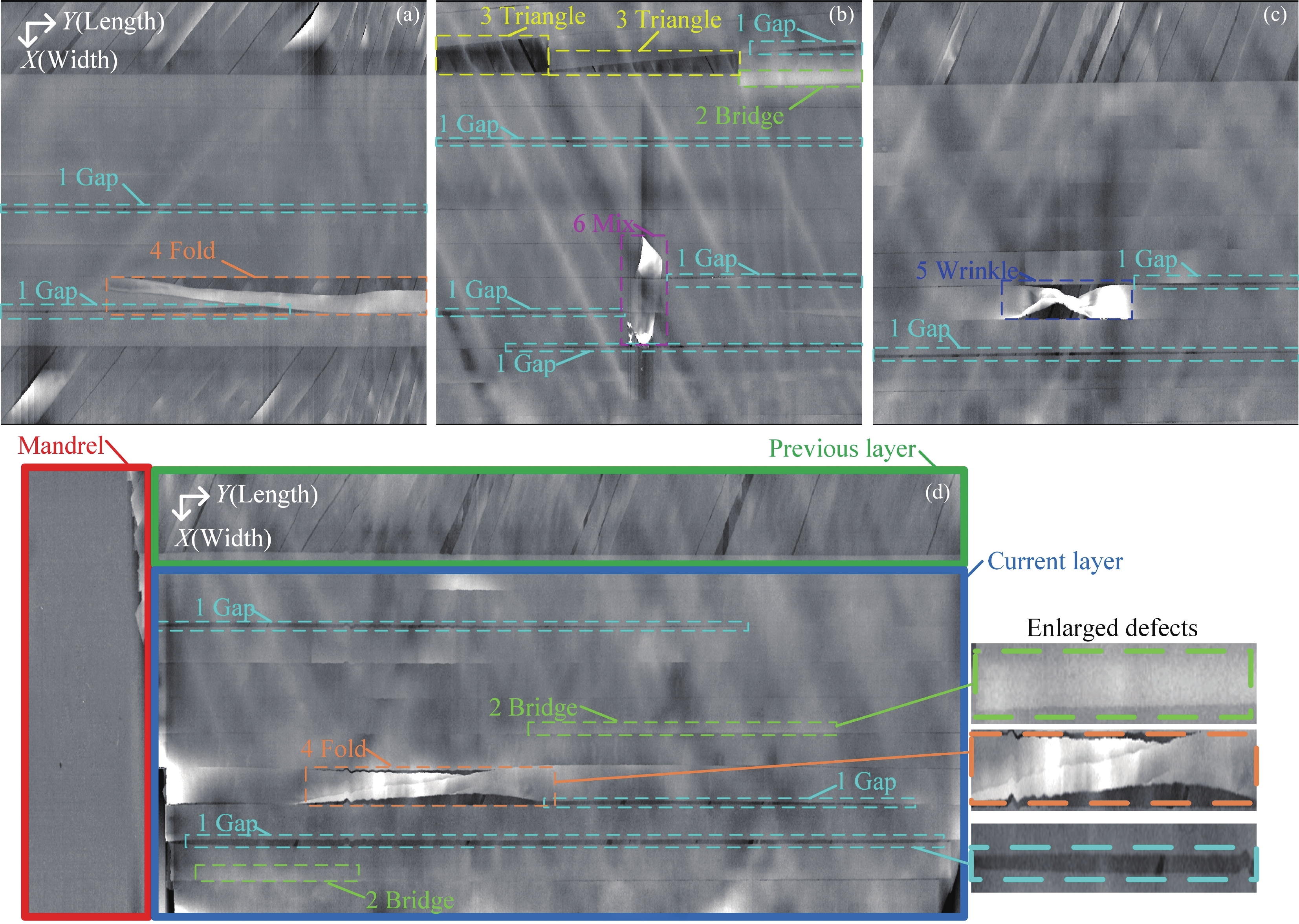
图 8 高度映射图:(a)~(c)各类缺陷的高度映射图;(d)一道纤维的高度映射图
Figure 8. Height mapping images: (a)-(c) Height mapping images of various defects; (d) Height mapping image of a course fibers
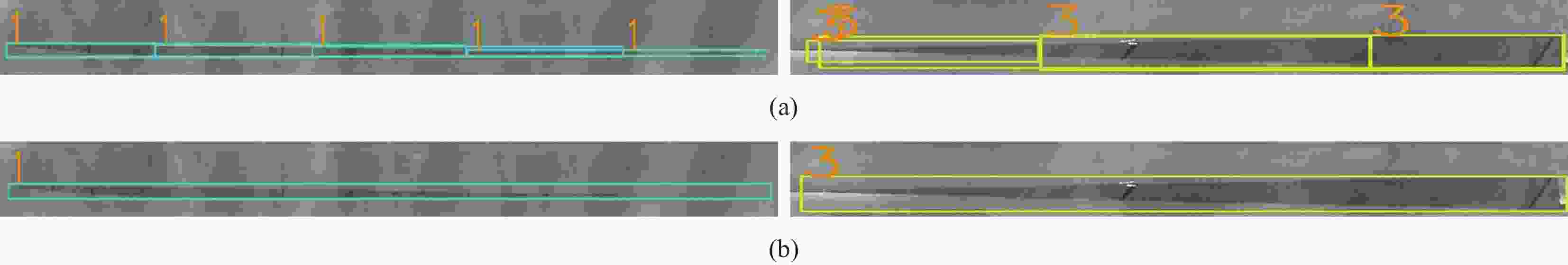
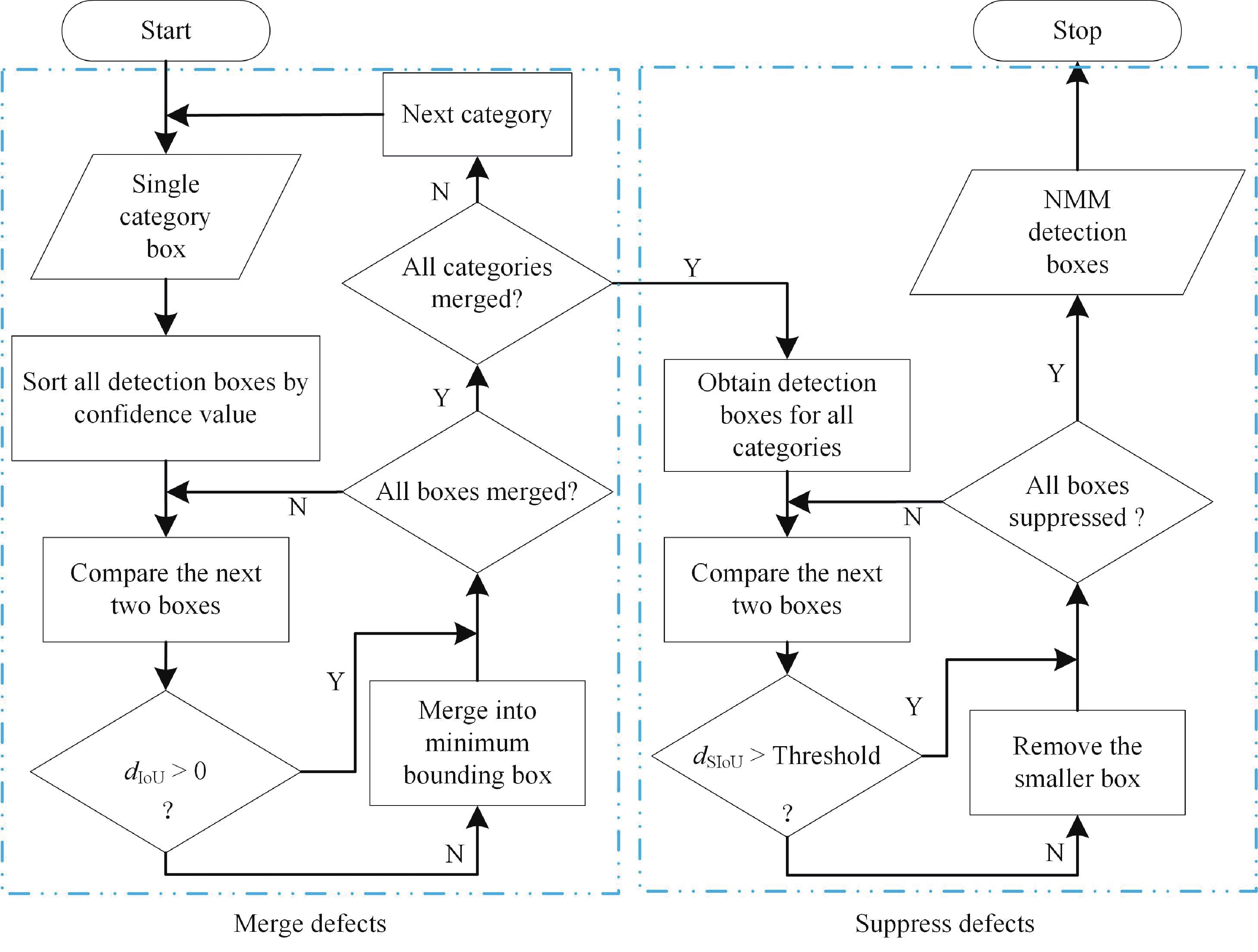
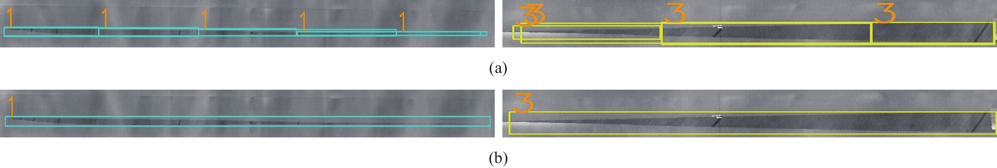
图 12 后处理方法对比细节图:(a)传统非极大值抑制 (NMS)后处理方法;(b)新型的NMM后处理方法
Figure 12. Comparison details of post-processing methods: (a) Traditional non maximum suppression (NMS) post-processing method; (b) New NMM post-processing method
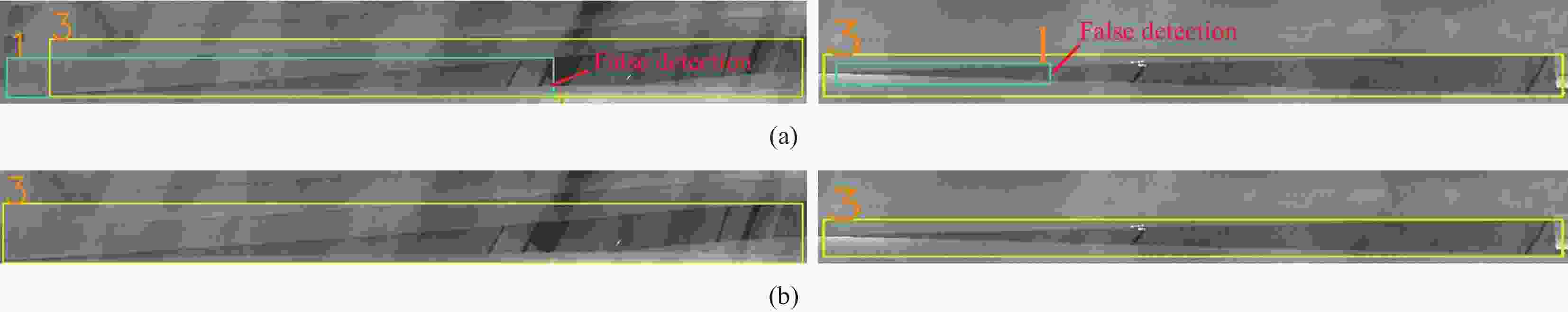
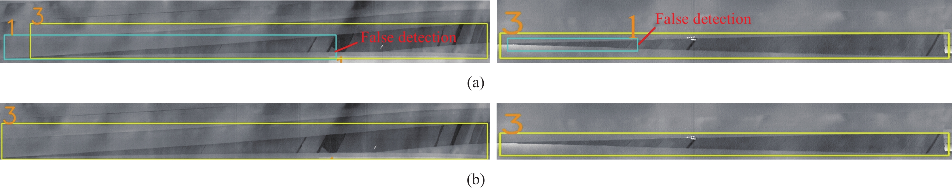
图 13 抑制误检细节对比图:(a)传统交并比;(b)改进的小化交并比
Figure 13. Comparison details for suppressing false detection: (a) Traditional intersection over union; (b) Improved smaller intersection over union
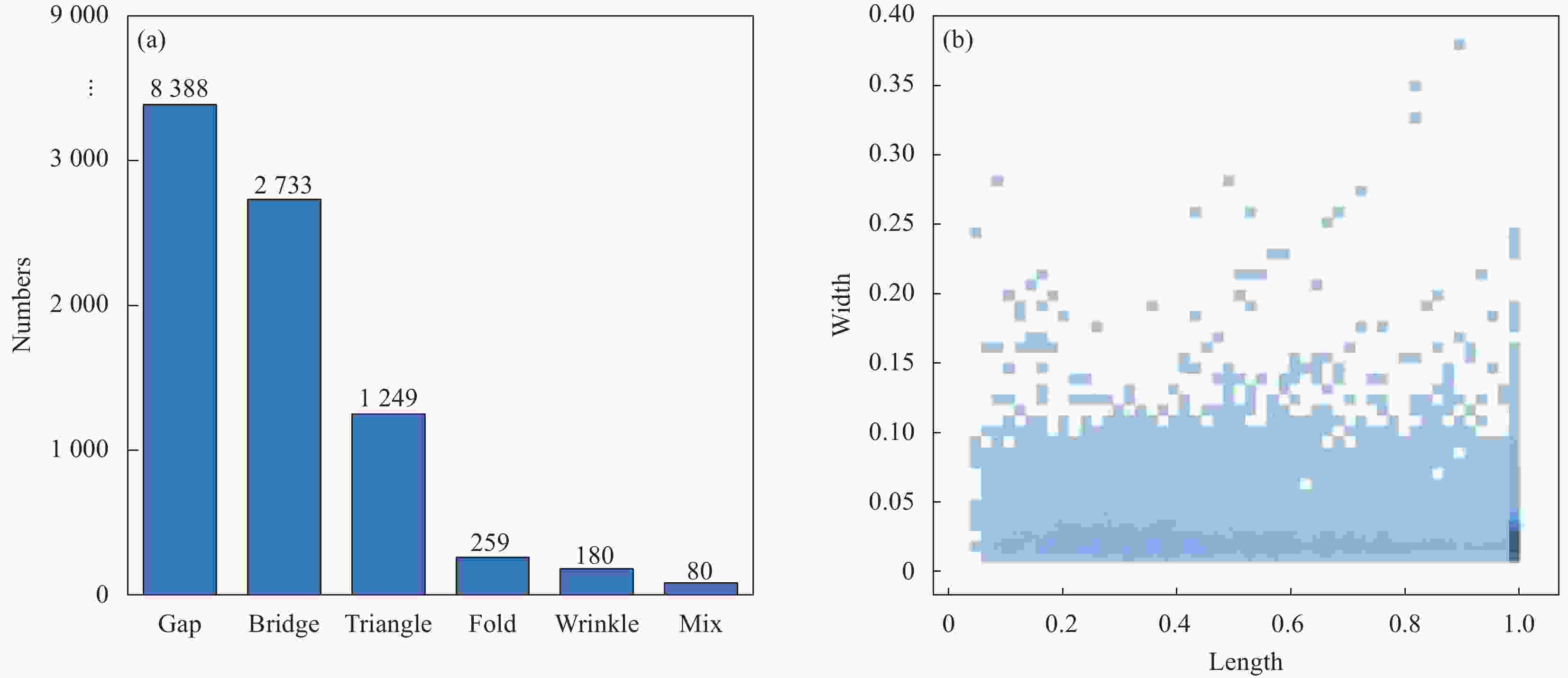
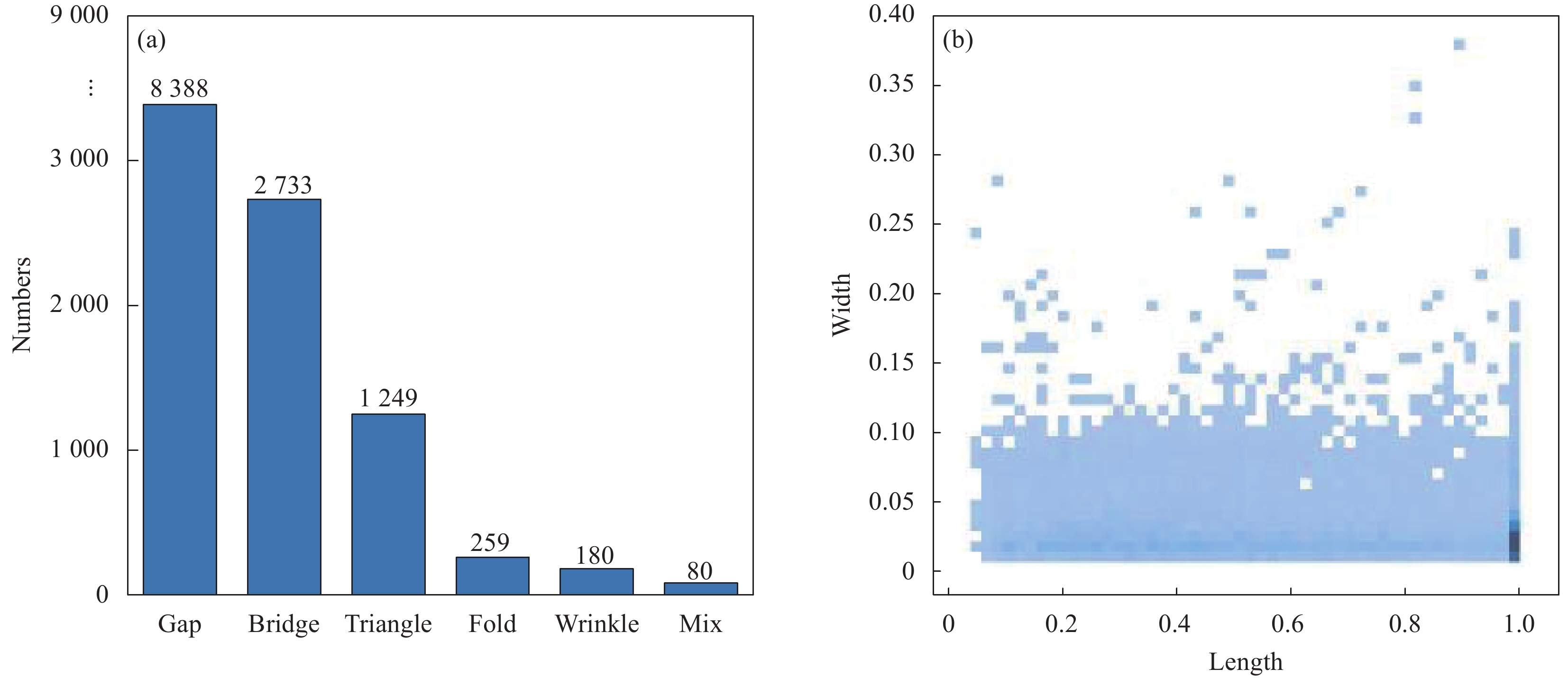
图 14 数据集中的缺陷特征:(a)缺陷标签数量;(b)缺陷总体长宽分布(已归一化)
Figure 14. Defect characteristics in dataset: (a) Number of defect instances; (b) Defect length and width distribution (normalized)
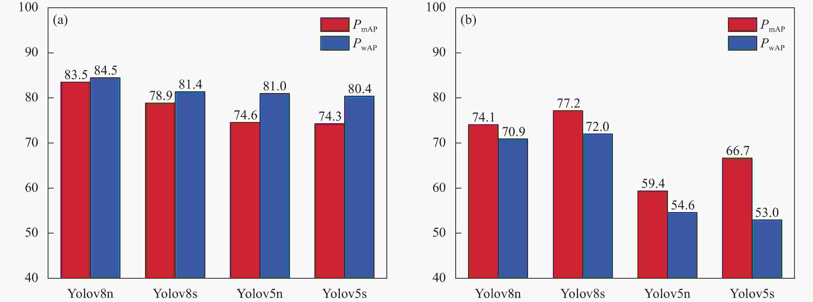
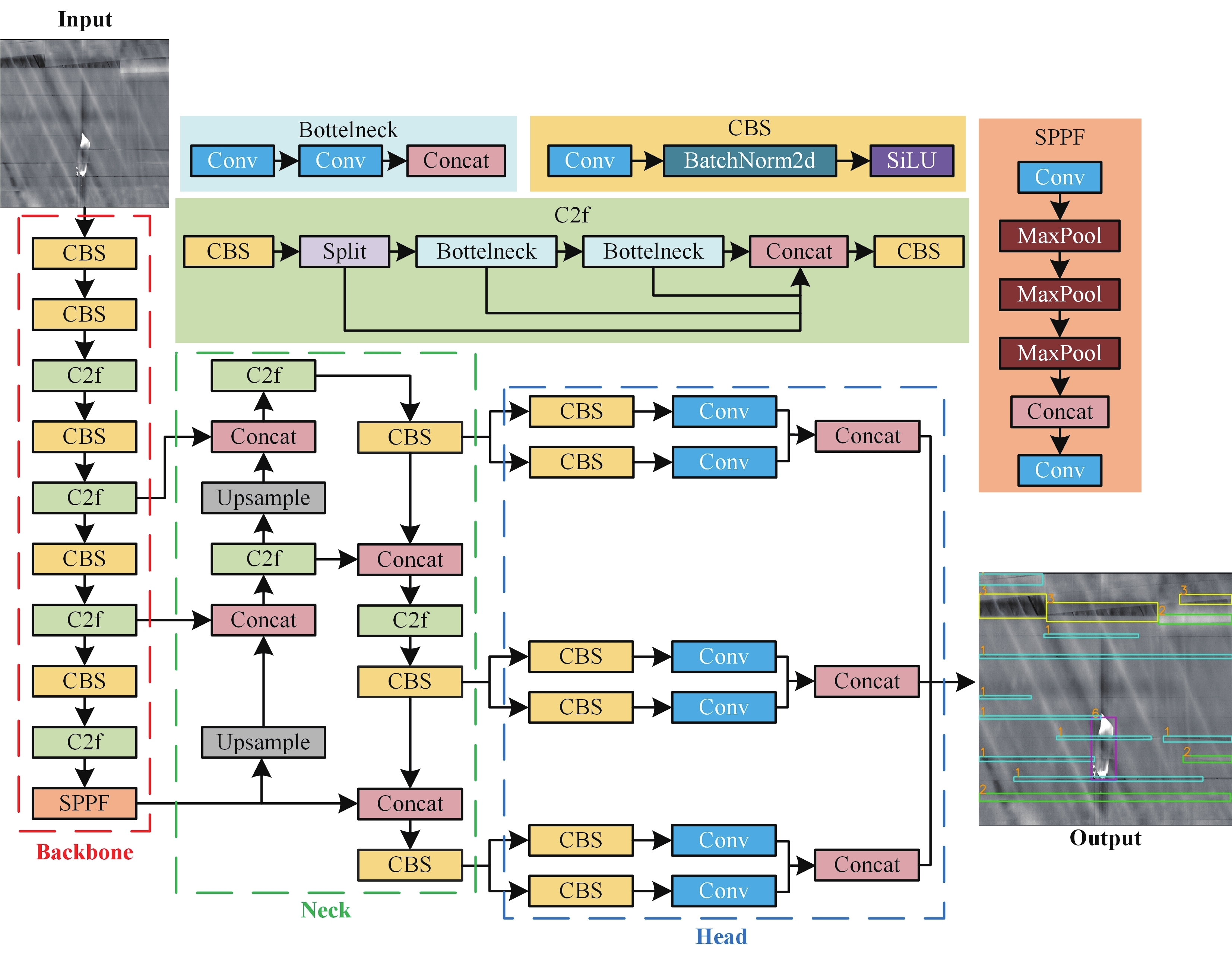
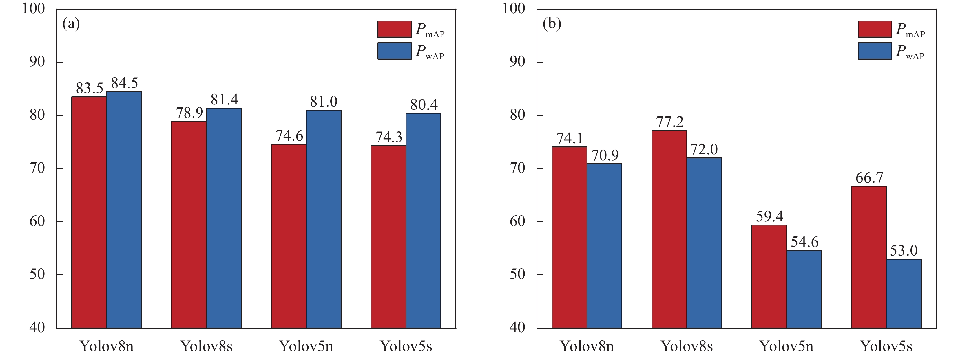
图 15 YOLO模型实验结果:(a)输入尺寸为640×640;(b)输入尺寸为
1600 ×1600 Figure 15. Experimental results of YOLO: (a) Input size is 640×640; (b) Input size is
1600 ×1600 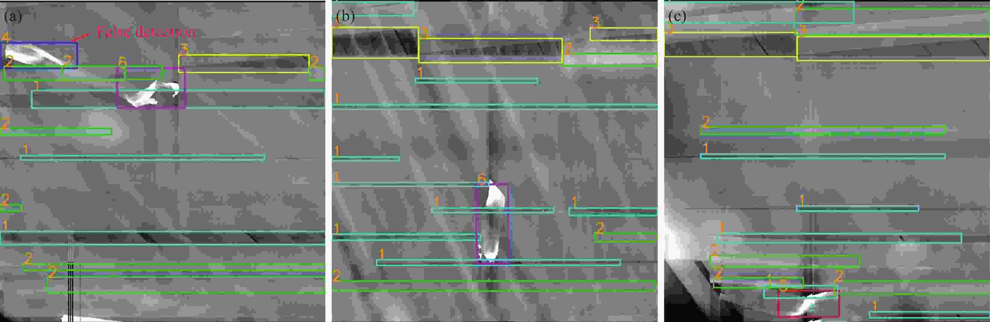
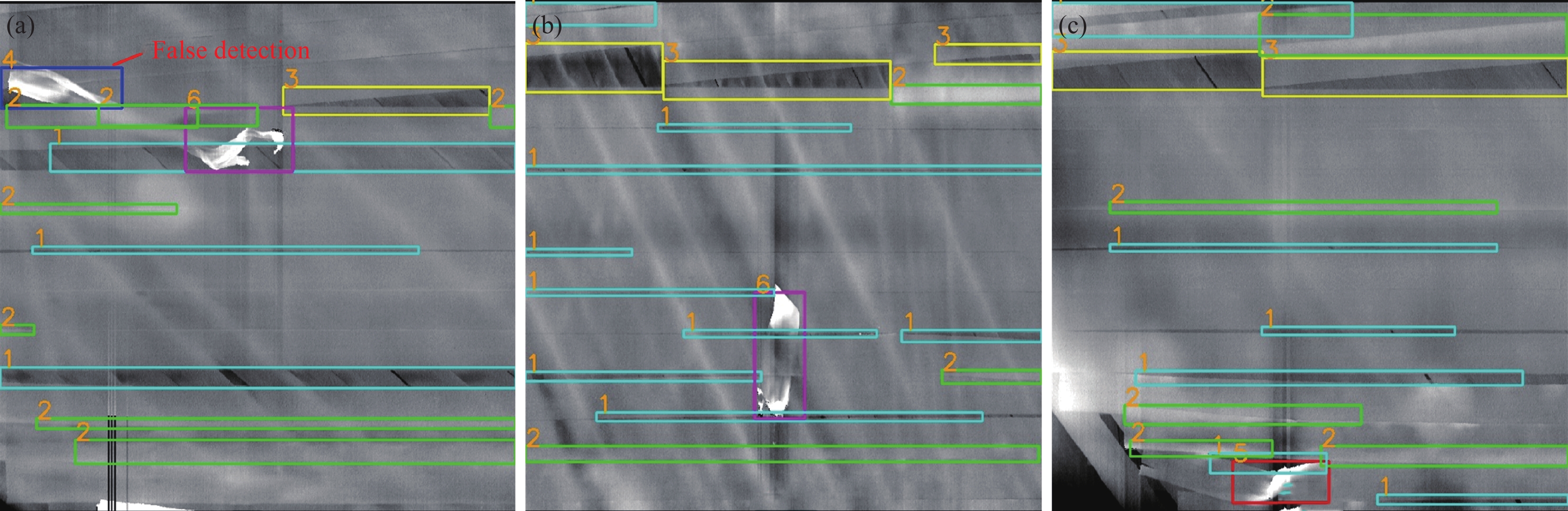
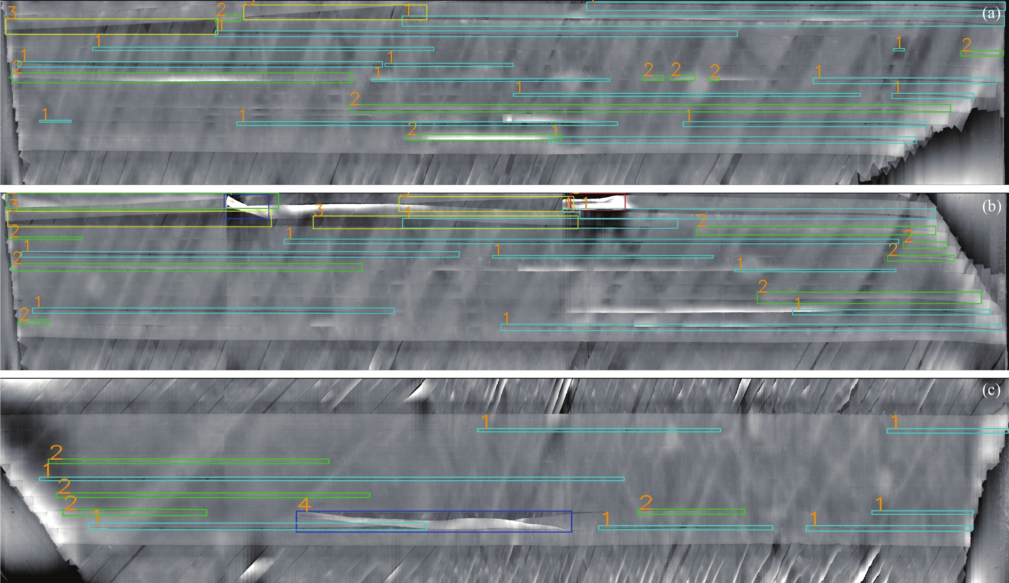
图 16 单张图片实际检测结果((a)、(b)、(c)包含不同缺陷的检测示例:1-间隙,2-搭接,3-三角区,4-翻折,5-褶皱,6-夹杂)
Figure 16. Actual detection results of single image ((a), (b), (c) examples of detection containing different defects: 1-gap, 2-bridge, 3-triangle, 4-fold, 5-wrinkle, 6-mix)
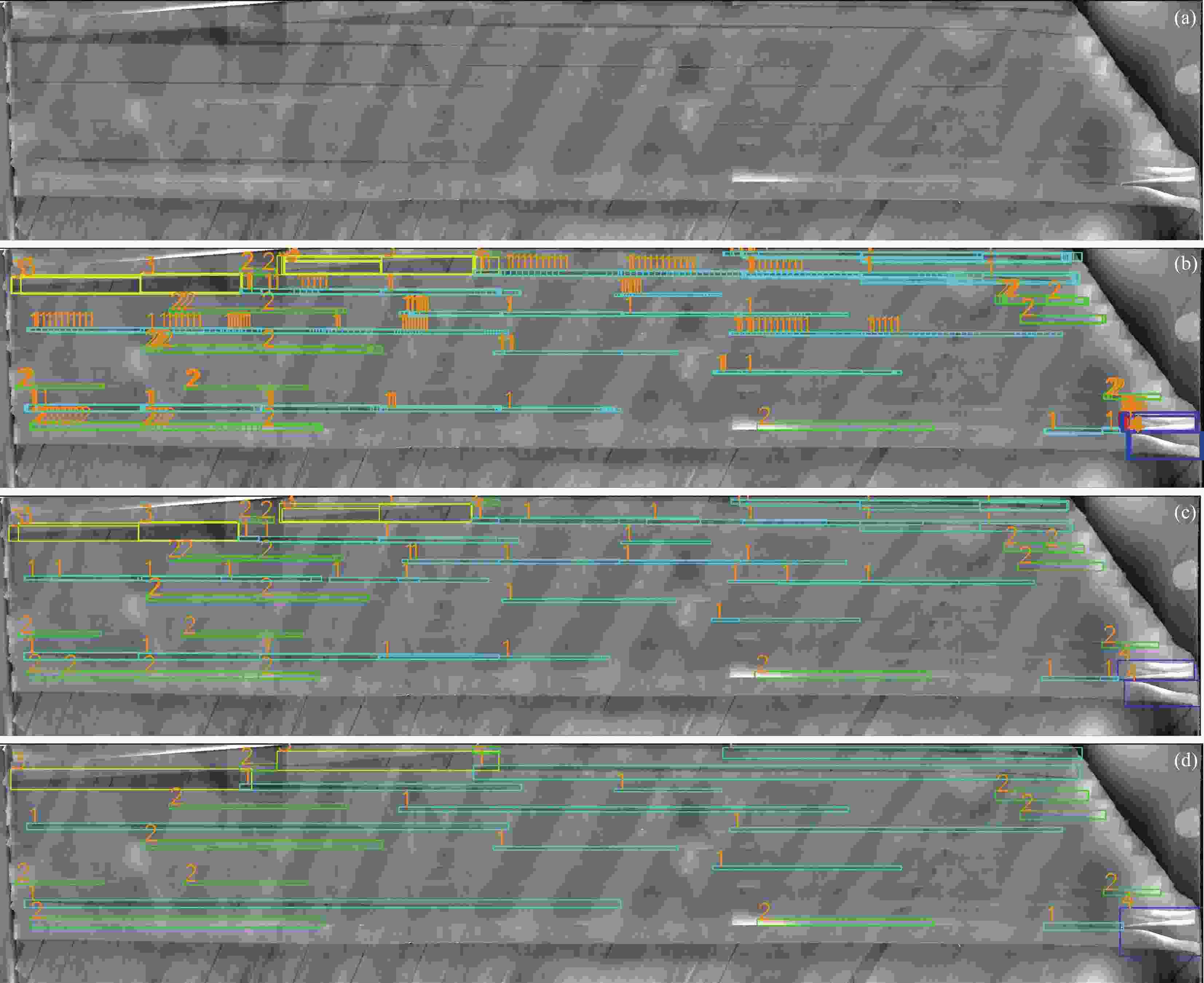
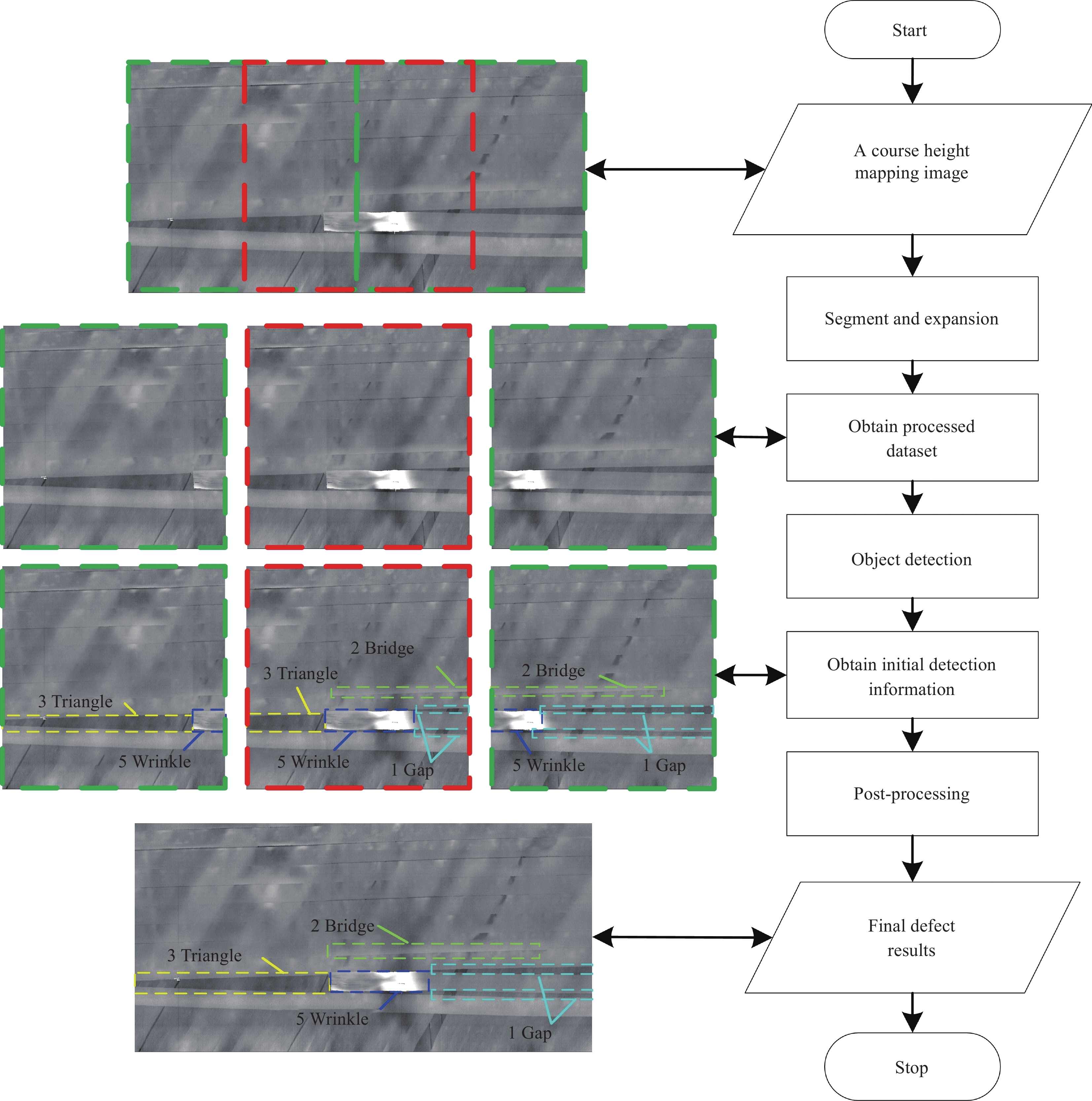
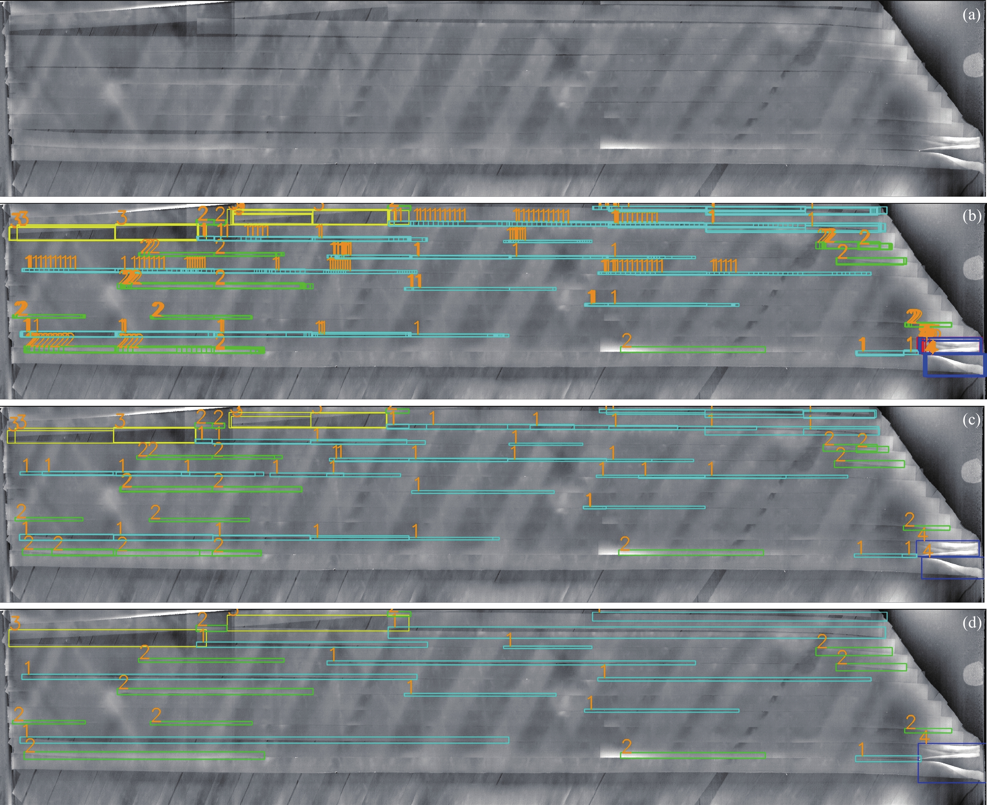
图 17 不同结果对比:(a)一带纤维的高度映射图;(b)神经网络初始输出(包含大量检测框);(c)传统NMS后处理方法;(d) NMM后处理方法结果
Figure 17. Comparison of different results: (a) Height mapping image of a course fibers; (b) Output of the neural network (including a large number of detection boxes); (c) Traditional NMS post-processing method; (d) Our NMM post-processing method
表 1 铺丝缺陷定义
Table 1. Definition of fiber placement defects
Category Number Definition Size Causes Gap 1 Gap between two fibers Widest part exceeds 2 mm Laying errors, complex surfaces, or unstable fibers Bridge 2 Overlapping part at the edge of two fibers Widest part exceeds 1.5 mm Laying errors, complex surfaces, or unstable fibers Triangle 3 A triangular void with a regular shape at the cutting edge None During the design process, in order to lay out different shapes, there may be gaps at the fiber cutting edge Fold/Reverse 4 Fibers have flipped over None Tensioner error or laying path too long Wrinkle/Blister 5 irregular deformation on the fiber surface None turning radius too small or fibers not fully adhering to the mandrel Mix 6 Foreign objects in the layer None Resin adhesive accumulates due to friction ,or foreign objects adhering to the layer  下载: 导出CSV
表 2 传感器参数
Table 2. Sensor parameters
Parameter type Value Z-axis reference distance/mm 70 X-axis width/mm 66 X-axis contour point numbers 1600 Interval between
X-axis points/μm50
下载: 导出CSV
表 3 目标检测神经网络实验结果
Table 3. Experimental results of target detection neural network
Model Input size P PmAP PwAP GPU detection
speed /fpsGap Bridge Triangle Fold Wrinkle Mix YOLOv8 n 640×640 86.1 82.0 85.8 89.5 82.9 74.6 83.5 84.5 143 1600 ×1600 69.6 67.1 79.1 85.6 77.6 65.8 74.1 70.9 33 s 640×640 83.0 81.3 82.4 84.6 72.2 69.8 78.9 81.4 106 1600 ×1600 68.7 69.2 81.7 89.2 80.2 73.5 77.2 72.0 0.9 YOLOv5 n 640×640 88.9 73.6 77.4 80.3 63.1 64.6 74.6 81.0 129 1600 ×1600 50.6 52.5 69.6 75.7 66.4 41.7 59.4 54.6 28 s 640×640 87.0 74.2 81.9 69.7 71.3 61.8 74.3 80.4 124 1600 ×1600 43.1 53.9 57.1 94.5 85.0 66.7 66.7 53.0 26 Faster-RCNN 640×640 32.7 42.5 82.4 43.7 38.7 70.0 51.7 42.8 14 1600 ×1600 39.4 48.5 79.5 37.4 40.9 42.2 48.0 45.8 1.1 Notes:P are average precision of various defects; PmAP is mean average precision of model; PwAP is weighted average precision of model.
下载: 导出CSV
表 4 优化后YOLOv5的实验结果
Table 4. Experimental results of Optimized YOLOv5
Model Input size P PmAP PwAP GPU detection
speed /fpsGap Bridge Triangle Fold Wrinkle Mix YOLOv5 n 640×640 93.0 78.9 84.3 85.3 76.6 37.8 76.0 84.6 129 1600 ×1600 52.4 56.8 69.3 68.7 58.4 36.6 57.1 55.5 28 s 640×640 90.0 80.1 86.0 85.0 77.3 68.9 81.2 85.2 124 1600 ×1600 56.5 54.8 71.3 76.5 70.1 40.4 61.6 58.4 26
下载: 导出CSV
表 5 真实的缺陷数量与预测缺陷数量
Table 5. Actual defect quantities and predicted defect quantities
Methods Gap Bridge Triangle Fold Wrinkle Mix Ground Truth 370 176 44 20 16 8 NMM 385 187 38 21 18 8 NMS 1317 429 117 48 33 10 Notes:NMS is non maximum suppression; NMM is non maximum merging.
下载: 导出CSV
表 6 误检率与漏检率
Table 6. False rate and Miss rate
Methods Parameters Gap Bridge Triangle Fold Wrinkle Mix OF OM NMS SF 77.8% 60.6% 68.4% 62.5% 30.0% 30.0% 72.0% 14.8% SM 20.5% 4.0% 15.9% 9.5% 6.25% 12.5% NMM SF 6.5% 7.0% 10.5% 14.3% 11.1% 12.5% 7.3% 4.1% SM 2.7% 1.1% 22.7% 14.3% 0.0% 12.5% Notes:SF and SM is false and miss rate of single defect; OF and OM is overall fase and miss rate.
下载: 导出CSV
-
[1] 王显峰, 段少华, 唐珊珊, 等. 复合材料自动铺放技术在航空航天领域的研究进展[J]. 航空制造技术, 2022, 65(16): 64-77.WANG Xianfeng, DUAN Shaohua, TANG Shanshan, et al. Progress of composite automated placement technology in aviation field[J]. Aeronautical Manufacturing Technology, 2022, 65(16): 64-77(in Chinese). [2] 肖军, 李勇, 李建龙. 自动铺放技术在大型飞机复合材料结构件制造中的应用[J]. 航空制造技术, 2008, (1): 50-53. doi: 10.3969/j.issn.1671-833X.2008.01.009Xiao Jun, Li Yong, Li Jianlong. The application of automatic laying technology in the manufacturing of composite structural components for large aircraft[J]. Aeronautical Manufacturing Technology, 2008, (1): 50-53(in Chinese). doi: 10.3969/j.issn.1671-833X.2008.01.009 [3] 柯映林, 曲巍崴, 李江雄, 等. 碳纤维复合材料结构件自动铺放技术与装备研究进展[J]. 机械工程学报, 2023, 59(20): 401-435. doi: 10.3901/JME.2023.20.401Ke Yinglin, Qu Weiwei, Li Jiangxiong, et al. Researches on Automated Placement Technologies and Equipment for Carbon Fiber Reinforced Composites: A State-of-the-art Review[J]. JOURNAL OF MECHANICAL ENGINEERING, 2023, 59(20): 401-435(in Chinese). doi: 10.3901/JME.2023.20.401 [4] Wang Z, Pei C, Zhang Z, et al. Quantitative test of delamination defects in CFRP with surface interference by laser thermography[J]. Infrared Physics & Technology, 2024, 136: 105046. [5] Halbritter A, Harper R. Big parts demand big changes to the fiber placement status quo[J]. SME composites manufacturing, 2012, 2012. [6] Wen L, Li S, Dong Z, et al. Research on Automated Fiber Placement Surface Defect Detection Based on Improved YOLOv7[J]. Applied Sciences, 2024, 14(13): 5657. doi: 10.3390/app14135657 [7] Schmidt C, Hocke T, Denkena B. Deep learning-based classification of production defects in automated-fiber-placement processes[J]. Production Engineering, 2019, 13: 501-509. doi: 10.1007/s11740-019-00893-4 [8] Engelbart R W, Hannebaum R. Verification of tow cut for automatic fiber placement: U. S. Patent 7, 807, 002[P]. 2010-10-5. [9] Engelbart R W, Hannebaum R, Rector E. Mapping tow splices in composite structures: U. S. Patent 8, 753, 458[P]. 2014-6-17. [10] Oldani T. Visual fiber placement inspection: U. S. Patent 7, 835, 567[P]. 2010-11-16. [11] Denkena B, Schmidt C, Völtzer K, et al. Thermographic online monitoring system for Automated Fiber Placement processes[J]. Composites Part B: Engineering, 2016, 97: 239-243. doi: 10.1016/j.compositesb.2016.04.076 [12] 康硕, 柯臻铮, 王璇, 等. 基于红外和可见光图像融合的铺丝缺陷检测方法[J]. 航空学报, 2022, 43(3): 564-576. doi: 10.7527/j.issn.1000-6893.2022.3.hkxb202203045Kang Shuo, Ke Zhenzheng, Wang Xuan, et al. Detection method of defects in automatic fiber placement based on fusion of infrared and visible images[J]. Acta Aeronautica et Astronautica Sinica, 2022, 43(3): 564-576(in Chinese). doi: 10.7527/j.issn.1000-6893.2022.3.hkxb202203045 [13] 马少博, 文立伟, 王若舟, 等. 复合材料自动铺放表面缺陷检测技术研究进展[J]. 复合材料科学与工程, 2020, (12): 121-128.Kang Shuo, Ke Zhenzheng, Wang Xuan, et al. Detection method of defects in automatic fiber placement based on fusion of infrared and visible images[J]. Acta Aeronautica et Astronautica Sinica, 2022, 43 (03): 564-576(in Chinese). [14] Cemenska J, Rudberg T, Henscheid M. Automated in-process inspection system for AFP machines[J]. Additive Manufacturing of Aerospace Composite Structures: Fabrication and Reliability, 2017, 8(2): 35. [15] Brasington A, Sacco C, Halbritter J, et al. Automated fiber placement: A review of history, current technologies, and future paths forward[J]. Composites Part C: Open Access, 2021, 6: 100182. doi: 10.1016/j.jcomc.2021.100182 [16] Meister S, Wermes M A M, Stüve J, et al. Review of image segmentation techniques for layup defect detection in the Automated Fiber Placement process: A comprehensive study to improve AFP inspection[J]. Journal of Intelligent Manufacturing, 2021, 32(8): 2099-2119. doi: 10.1007/s10845-021-01774-3 [17] Meister S, Möller N, Stüve J, et al. Synthetic image data augmentation for fibre layup inspection processes: Techniques to enhance the data set[J]. Journal of Intelligent Manufacturing, 2021, 32(6): 1767-1789. doi: 10.1007/s10845-021-01738-7 [18] Maass D. Progress in automated ply inspection of AFP layups[J]. Reinforced Plastics, 2015, 59(5): 242-245. doi: 10.1016/j.repl.2015.05.002 [19] Tang Y, Wang Q, Wang H, et al. A novel 3D laser scanning defect detection and measurement approach for automated fibre placement[J]. Measurement Science and Technology, 2021, 32(7): 075201. doi: 10.1088/1361-6501/abda95 [20] Tang Y, Wang Q, Cheng L, et al. An in-process inspection method integrating deep learning and classical algorithm for automated fiber placement[J]. Composite Structures, 2022, 300: 116051. doi: 10.1016/j.compstruct.2022.116051 [21] Sacco C, Radwan A B, Harik R, et al. Automated Fiber Placement Defects: Automated Inspection and Characterization[C]//SAMPE 2018 Conference and Exhibition. 2018. [22] Sacco C. Machine learning methods for rapid inspection of automated fiber placement manufactured composite structures[D]. University of South Carolina, 2019. [23] Sacco C, Radwan A B, Anderson A, et al. Machine learning in composites manufacturing: A case study of Automated Fiber Placement inspection[J]. Composite Structures, 2020, 250: 112514. doi: 10.1016/j.compstruct.2020.112514 [24] Godbold M J, Sacco C M, Wehbe R, et al. An end-to-end AFP defect inspection and analysis tool[J]. SAMPE 2022, 2022. [25] Zambal S, Heindl C, Eitzinger C, et al. End-to-end defect detection in automated fiber placement based on artificially generated data[C]//Fourteenth international conference on quality control by artificial vision. SPIE, 2019, 11172: 371-378. [26] Meister S, Wermes M. Performance evaluation of CNN and R-CNN based line by line analysis algorithms for fibre placement defect classification[J]. Production Engineering, 2023, 17(3): 391-406. [27] 李津容, 葛广言, 冯晓冰, 等. 在机测量线激光传感器安装位姿的全局标定[J]. 仪器仪表学报, 2022, 43(9): 158-165.Li Jinrong, Ge Guangyan, Feng Xiaobing, et al. Global position calibration of 2D laser profiler for on-machine measurement[J]. Chinese Journal of Scientific Instrument, 2022, 43(9): 158-165(in Chinese). [28] 蔡坤, 陆尧胜. 基于中值滤波的心电基线校正方法的研究[J]. 医疗设备信息, 2004, (2): 5-7.Cai Kun, Lu Yaosheng. Study on a method of removal ECG baseline drift based on median filtering[J]. China Medical Devices, 2004, (2): 5-7(in Chinese). [29] 杨怀杰, 乔宝强, 黄笑, 等. 基于小波Mallat算法的自然电位曲线基线漂移校正方法研究[J]. 铀矿地质, 2024, 40(2): 294-300. doi: 10.3969/j.issn.1000-0658.2024.40.025Yang Huaijie, Qiao Baoqiang, Huang Xiao, et al. Study on the Correction Method for Baseline Drift of Spontaneous Potential Curve Based on Mallet Wavelet Algorithm[J]. Uranium Geology, 2024, 40(2): 294-300(in Chinese). doi: 10.3969/j.issn.1000-0658.2024.40.025 [30] Ronneberger O, Fischer P, Brox T. U-net: Convolutional networks for biomedical image segmentation[C]//Medical image computing and computer-assisted intervention–MICCAI 2015: 18th international conference, Munich, Germany, October 5-9, 2015, proceedings, part III 18. Springer International Publishing, 2015: 234-241. [31] Chen L C, Papandreou G, Kokkinos I, et al. Semantic image segmentation with deep convolutional nets and fully connected crfs[J]. arxiv preprint arxiv: 1412.7062, 2014. [32] Lin T Y, Dollár P, Girshick R, et al. Feature pyramid networks for object detection[C]//Proceedings of the IEEE conference on computer vision and pattern recognition. 2017: 2117-2125. [33] Liu S, Qi L, Qin H, et al. Path aggregation network for instance segmentation[C]// Proceedings of the IEEE conference on computer vision and pattern recognition. 2018: 8759-8768. [34] Bodla N, Singh B, Chellappa R, et al. Soft-NMS--improving object detection with one line of code[C]//Proceedings of the IEEE international conference on computer vision. 2017: 5561-5569. [35] Zhang Y F, Ren W, Zhang Z, et al. Focal and efficient IOU loss for accurate bounding box regression[J]. Neurocomputing, 2022, 506: 146-157. doi: 10.1016/j.neucom.2022.07.042 [36] Ren S, He K, Girshick R, et al. Faster r-cnn: Towards real-time object detection with region proposal networks[J]. Advances in neural information processing systems, 2015, 28. [37] Redmon J, Divvala S, Girshick R, et al. You only look once: Unified, real-time object detection[C]//Proceedings of the IEEE conference on computer vision and pattern recognition. 2016: 779-788. -

 下载:
下载:

 点击查看大图
计量
- 文章访问数: 49
- HTML全文浏览量: 18
- 被引次数: 0
