


Groove morphology enhancement and parameter design of metal-composite bonding
-
摘要: 金属-复合材料混合接头广泛存在于航空、船舶及汽车等领域,具有凹槽形貌的共固化金属-复合材料接头可保持复合材料结构的完整性和纤维的连续性。在被连接金属表面设计了±45°凹槽,评估了表面形貌对钢-玻璃纤维增强树脂复合材料(GFRP)接头胶接性能的影响,设计了单搭接拉伸剪切试验,验证胶接接头的剪切性能;在模拟中引入随机Weibull分布,定义内聚单元材料参数,结合矢量化用户材料(Vectorized user material,VUMAT)子程序模拟了接头的渐进失效过程,并建立±45°凹槽结构的代表性体积单元(Representative volume element,RVE)模型,分析了凹槽宽度和深度等参数对胶接接头的性能影响。研究表明,±45°凹槽结构可以显著提高钢-GFRP胶接接头的剪切强度,数值模拟强度和破坏模式与试验吻合;凹槽深度和宽度对结构胶接性能的影响显著,本文可为金属-复合材料接头的设计提供参考。
-
关键词:
- 胶接 /
- 沟槽结构 /
- 内聚单元 /
- 随机分布 /
- 代表性体积单元(RVE)
Abstract: Metal-composite hybrid joints are widely used in aviation, ship, and automobile. Co-cured metal-composite joints with groove morphology can maintain the integrity of the composite structure and the continuity of fibers. ±45° grooves were designed on the connected metal surface, and the influence of surface morphology on the bonding performance of steel-glass fiber reinforced polymer (GFRP) joints was evaluated. The single-lap joint tensile shear test was designed to verify the shear performance of the bonded joints. In the simulation, the random Weibull distribution was introduced to define the material parameters of the cohesive element, and the progressive failure process of the joint was simulated combined with the vectorized user material (VUMAT) subroutine. The representative volume element (RVE) model of ±45° groove structure was established to analyze the influence of groove width and depth on the adhesive joint. The research shows that the ±45° groove structure can significantly improve the shear strength of steel-GFRP adhesive joints, and the numerical simulation strength and failure mode are consistent with the experiment. The influence of groove depth and width on structural bonding performance is obvious. The research in this paper can provide a reference for the design of metal-composite joints. -

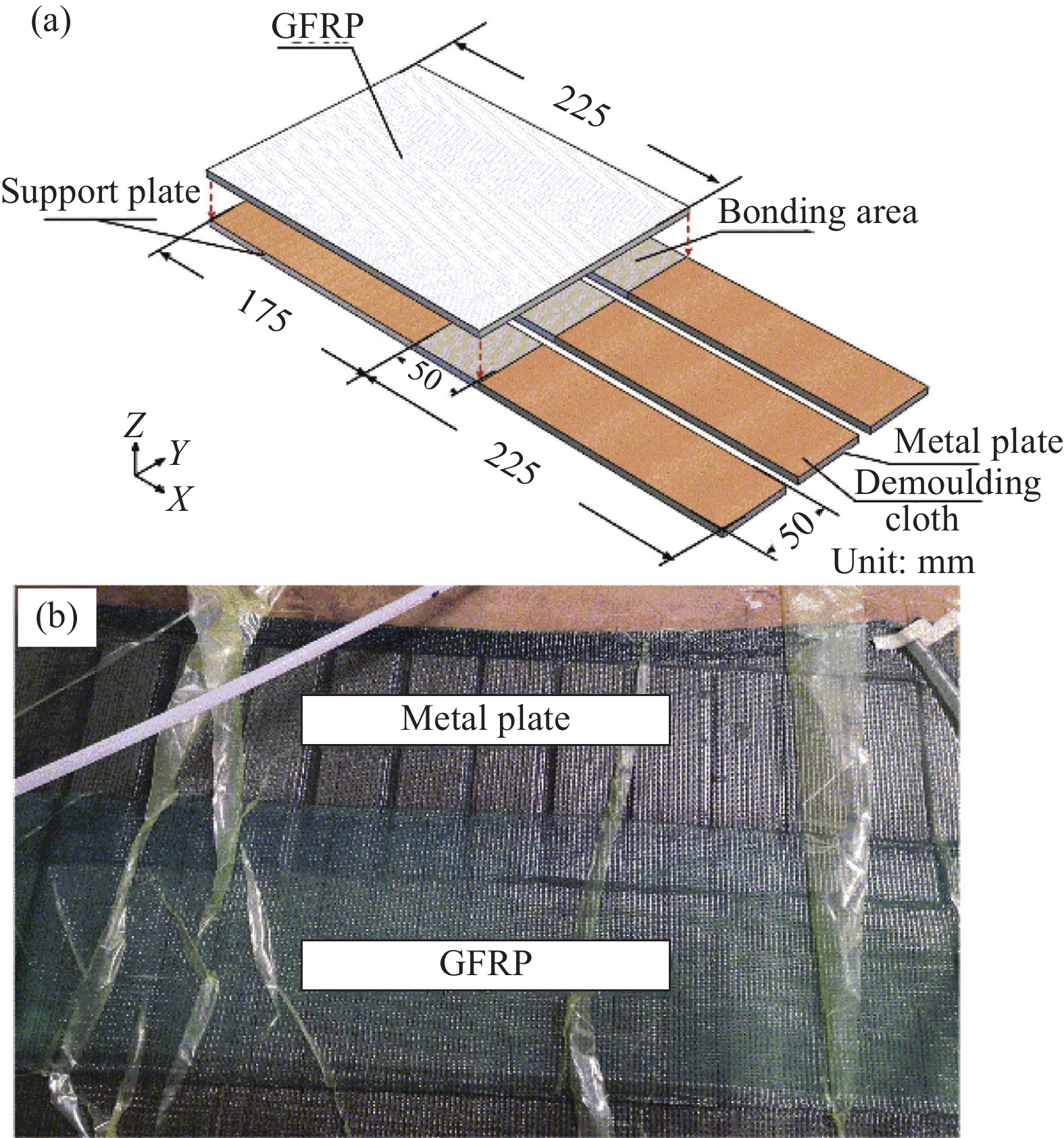
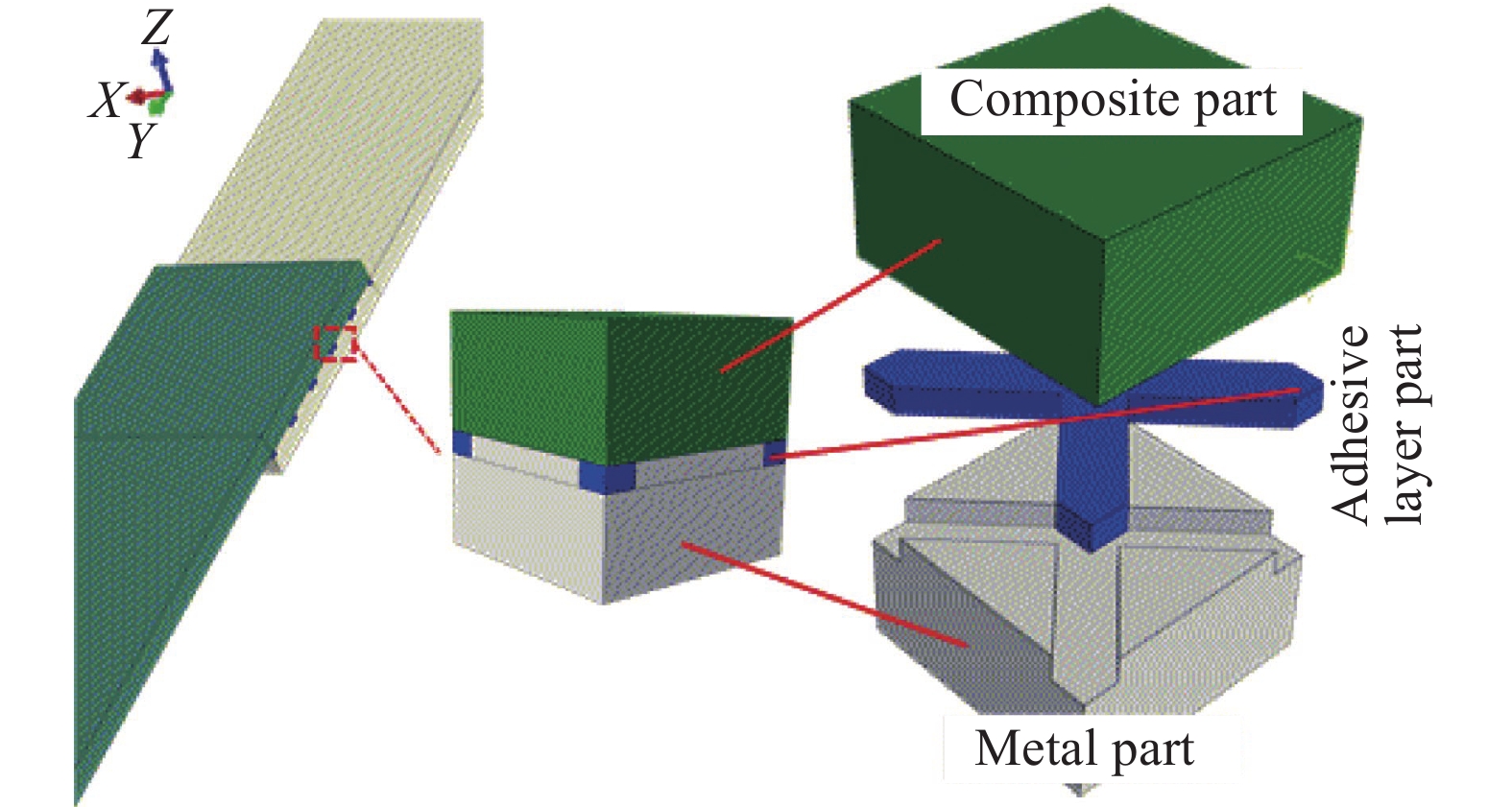
图 2 钢-GFRP接头的真空辅助成型工艺(VARI)过程:(a) 真空袋内各构件铺设顺序;(b) 抽真空后的试件制作
Figure 2. Vacuum assisted resin infusion (VARI) process of steel-GFRP joints: (a) Laying sequence of each component in the vacuum bag; (b) Specimen production after vacuuming
GFRP—Glass fiber reinforced polymer
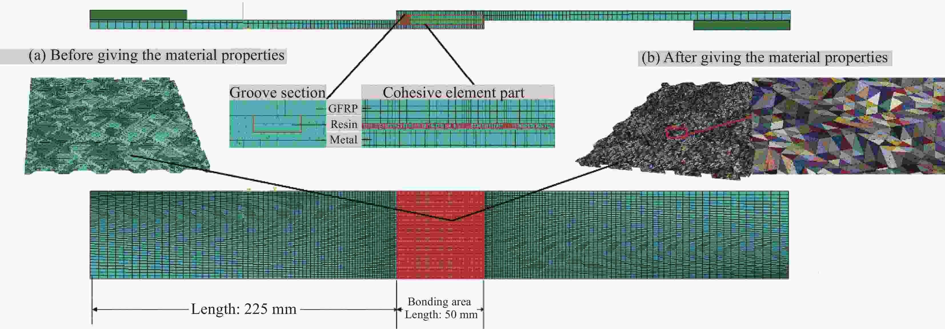
图 4 ±45°凹槽结构单搭接接头(SLJ)试件模型网格及边界条件
Figure 4. Mesh and boundary conditions for single lap joint (SLJ) specimen model with the ±45° groove structure
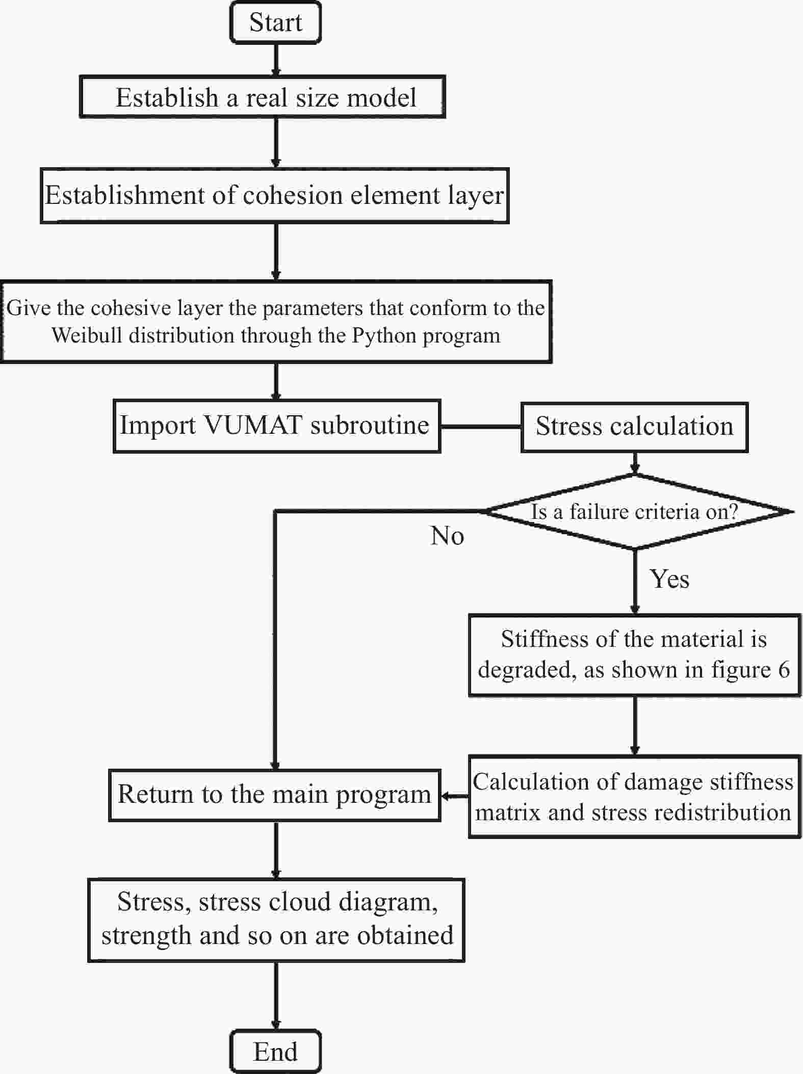
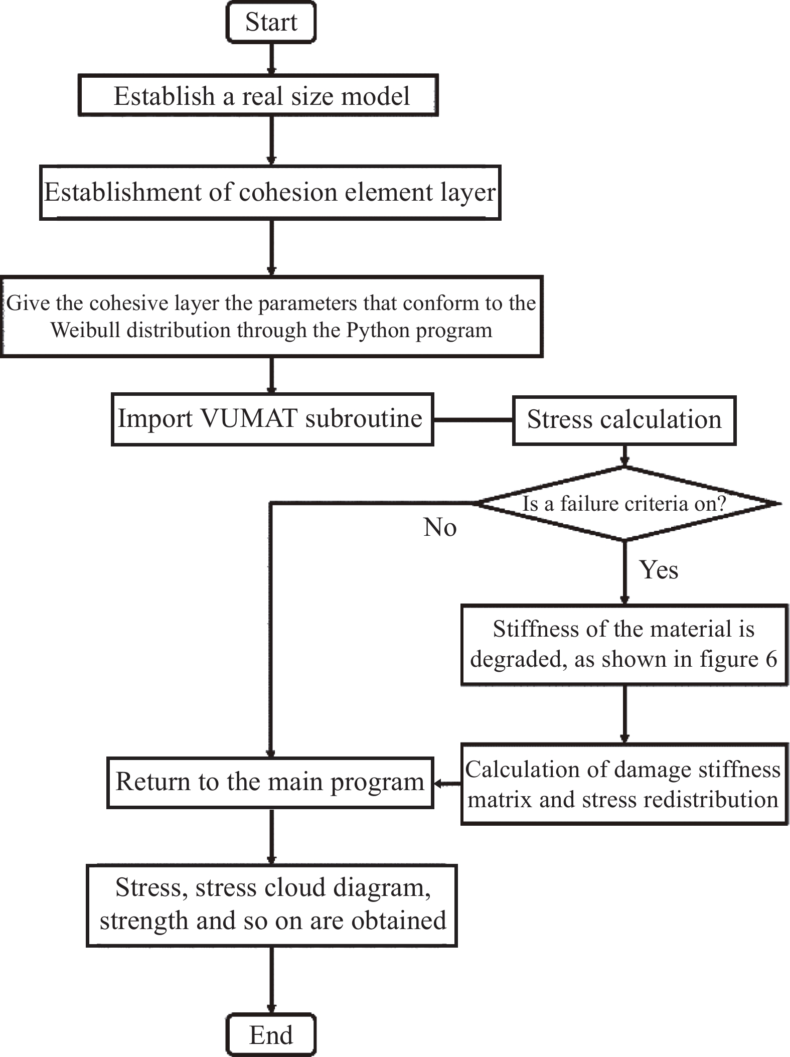
图 5 有限元仿真程序框图和子程序框图
Figure 5. Finite element simulation program and subroutine flowchart

图 6 钢-GFRP接头代表性体积单元(RVE)的定义与选取
Figure 6. Definition and selection of representative volume element (RVE) of steel-GFRP joint

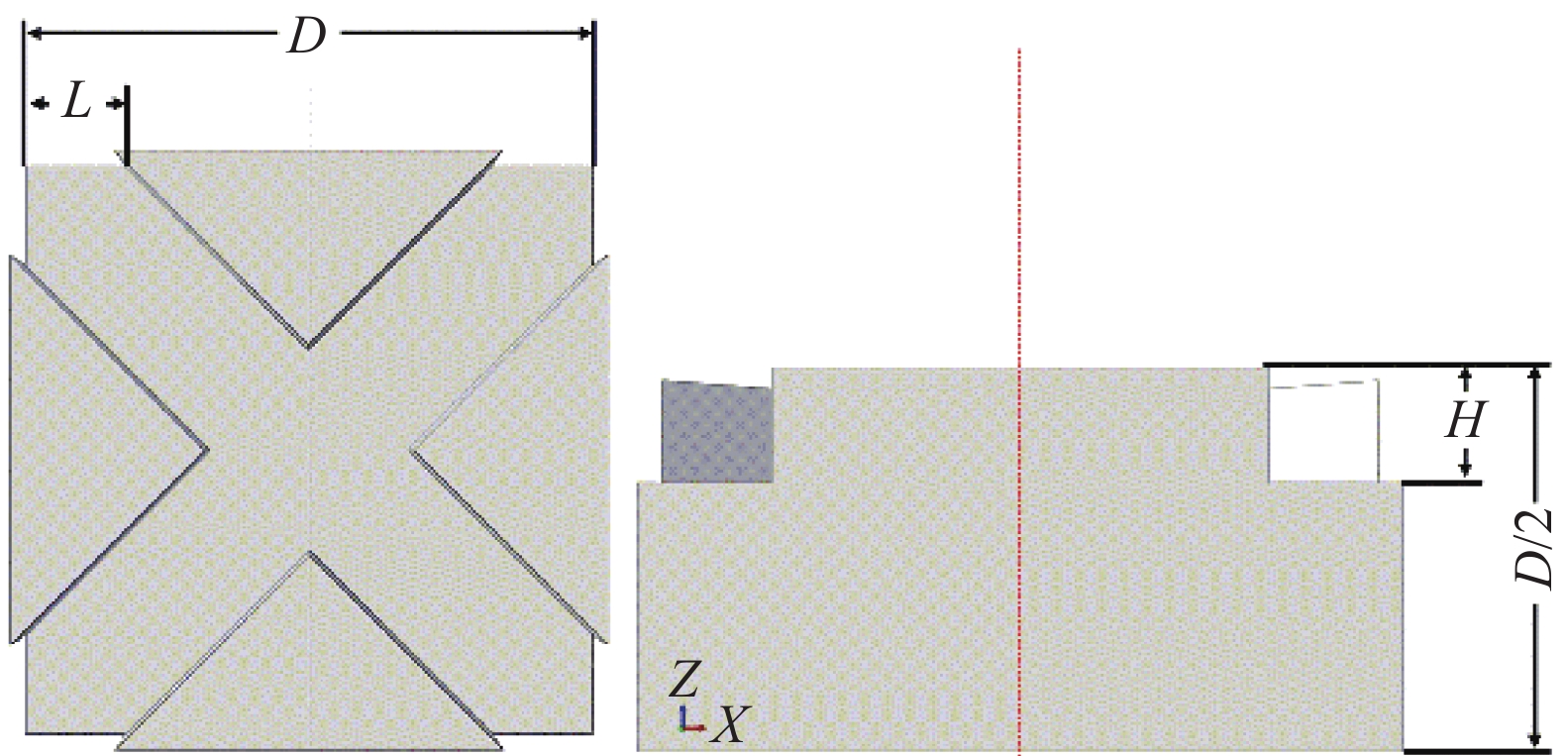
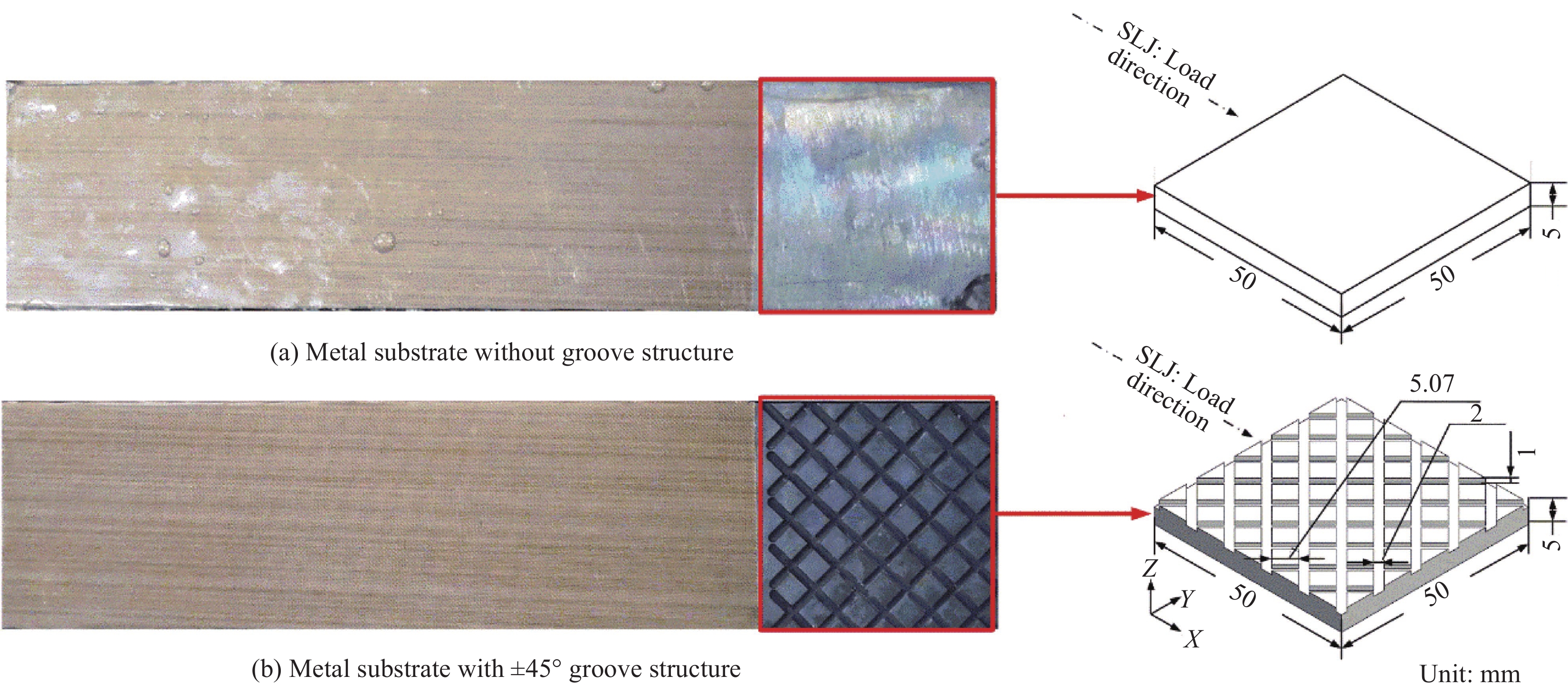
图 7 钢-GFRP接头RVE的边缘宽度和深度的定义
Figure 7. Definition of edge width and depth of RVE of steel-GFRP joint
D—Side length of RVE; L—Edge width; H—Groove depth

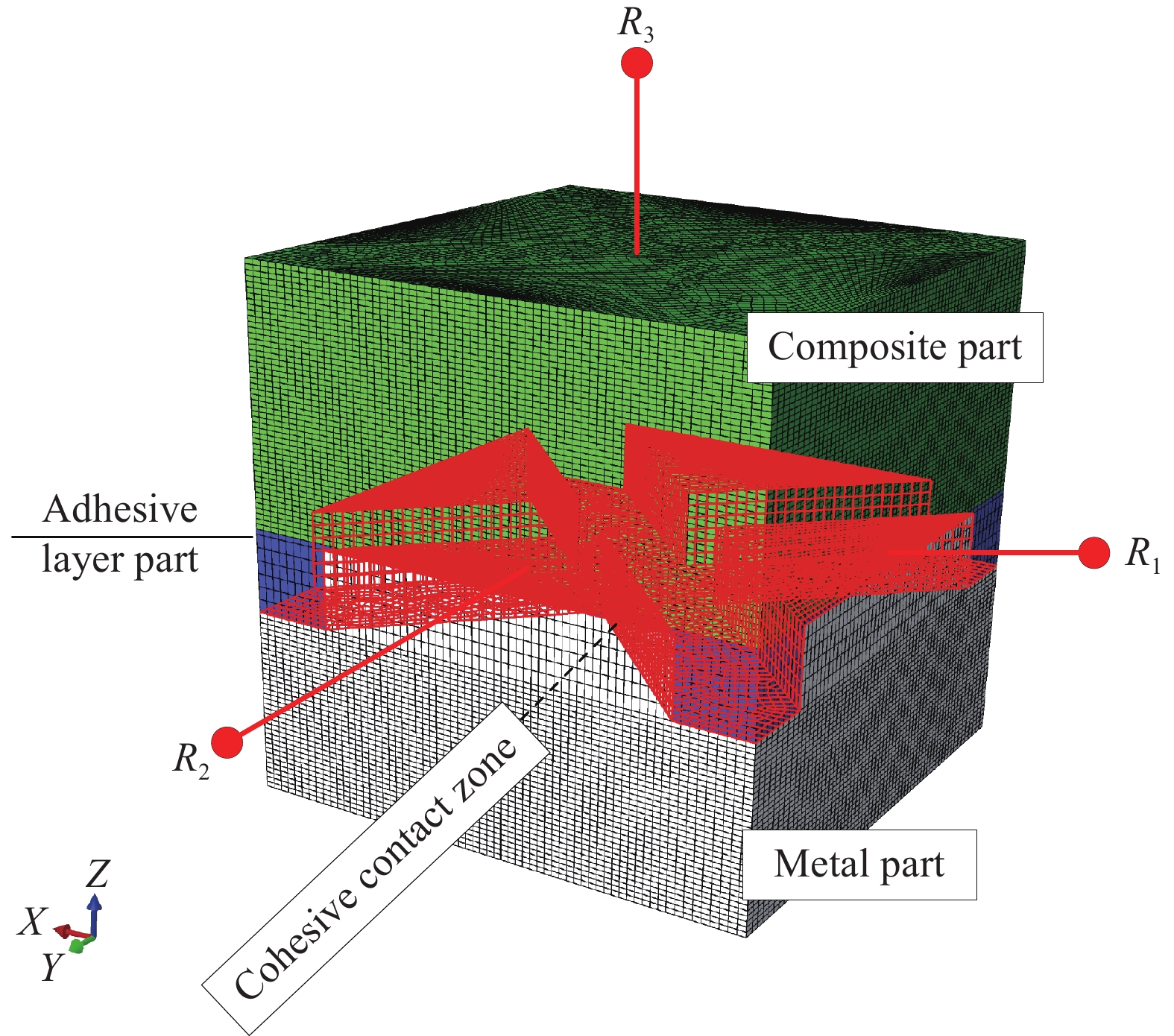
图 8 钢-GFRP接头RVE的网格划分和组件
Figure 8. Meshing and components of the RVE of steel-GFRP joint
R1-R3—Reference point associated with the corresponding boundary surface

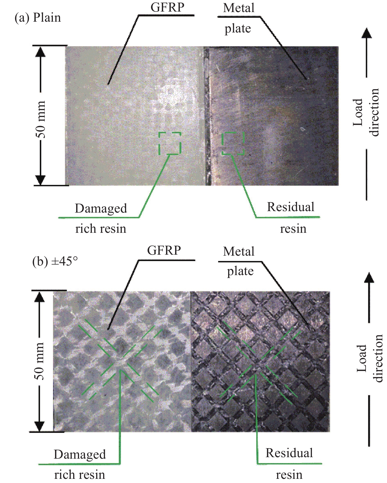
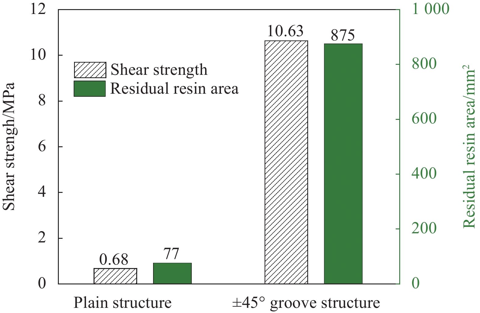
图 10 两组钢-GFRP胶接接头的剪切强度和树脂残留面积
Figure 10. Shear strength and residual resin area of the two sets of steel-GFRP adhesive joints

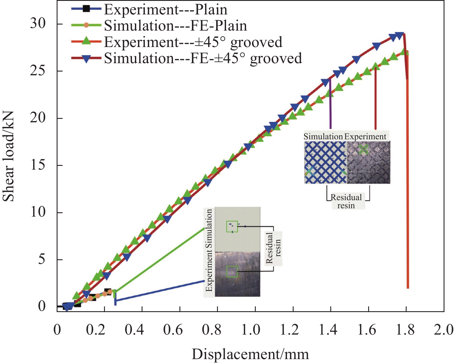
图 11 钢-GFRP接头模拟结果与试验结果对比
Figure 11. Comparison between the simulation results and test results of steel-GFRP joint
FE—Finite element
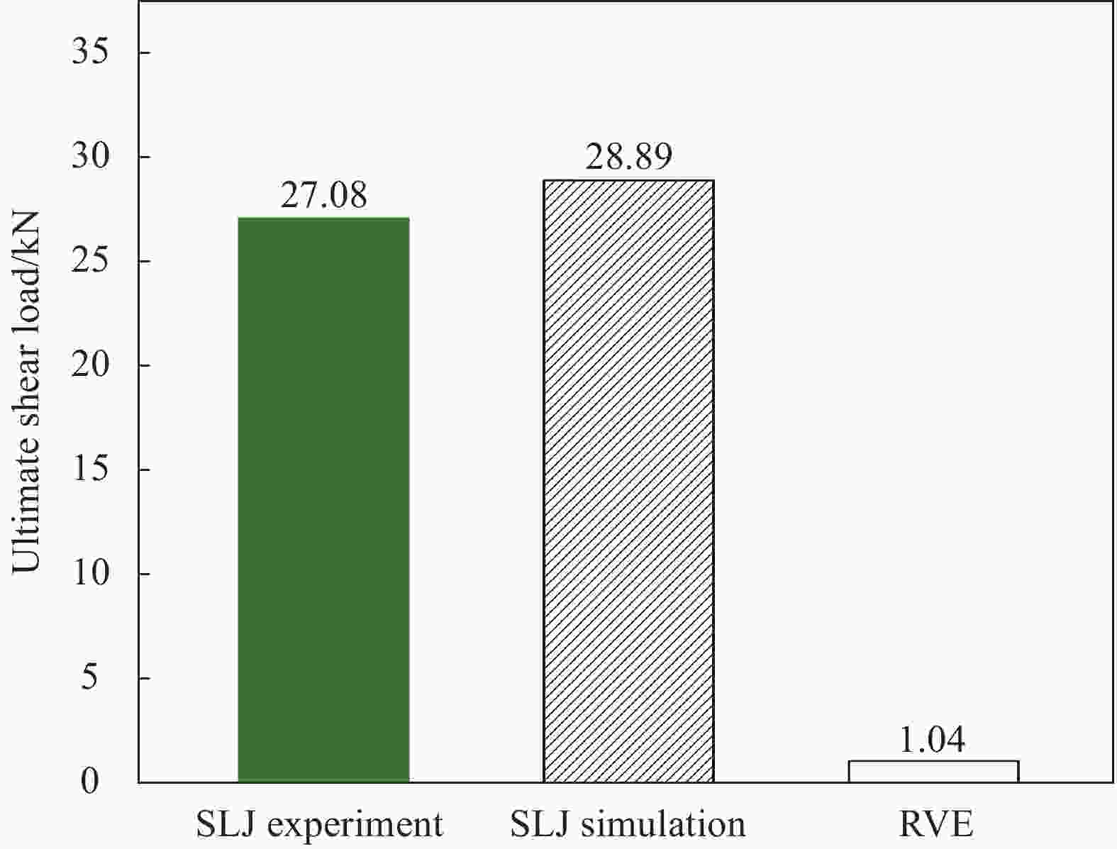
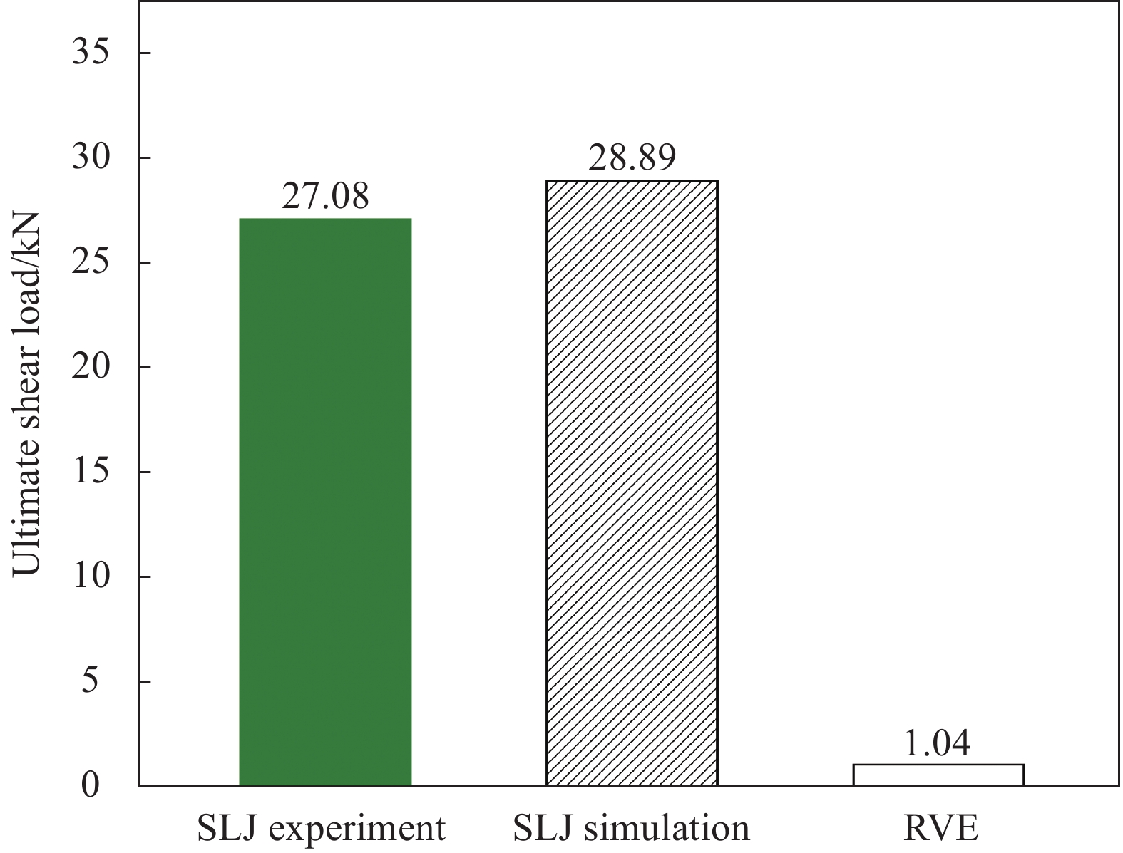
图 12 ±45°凹槽结构的钢-GFRP SLJ试验、仿真与RVE的极限载荷对比
Figure 12. Ultimate load comparison of test, simulation and RVE of steel-GFRP SLJ with ±45° groove structure
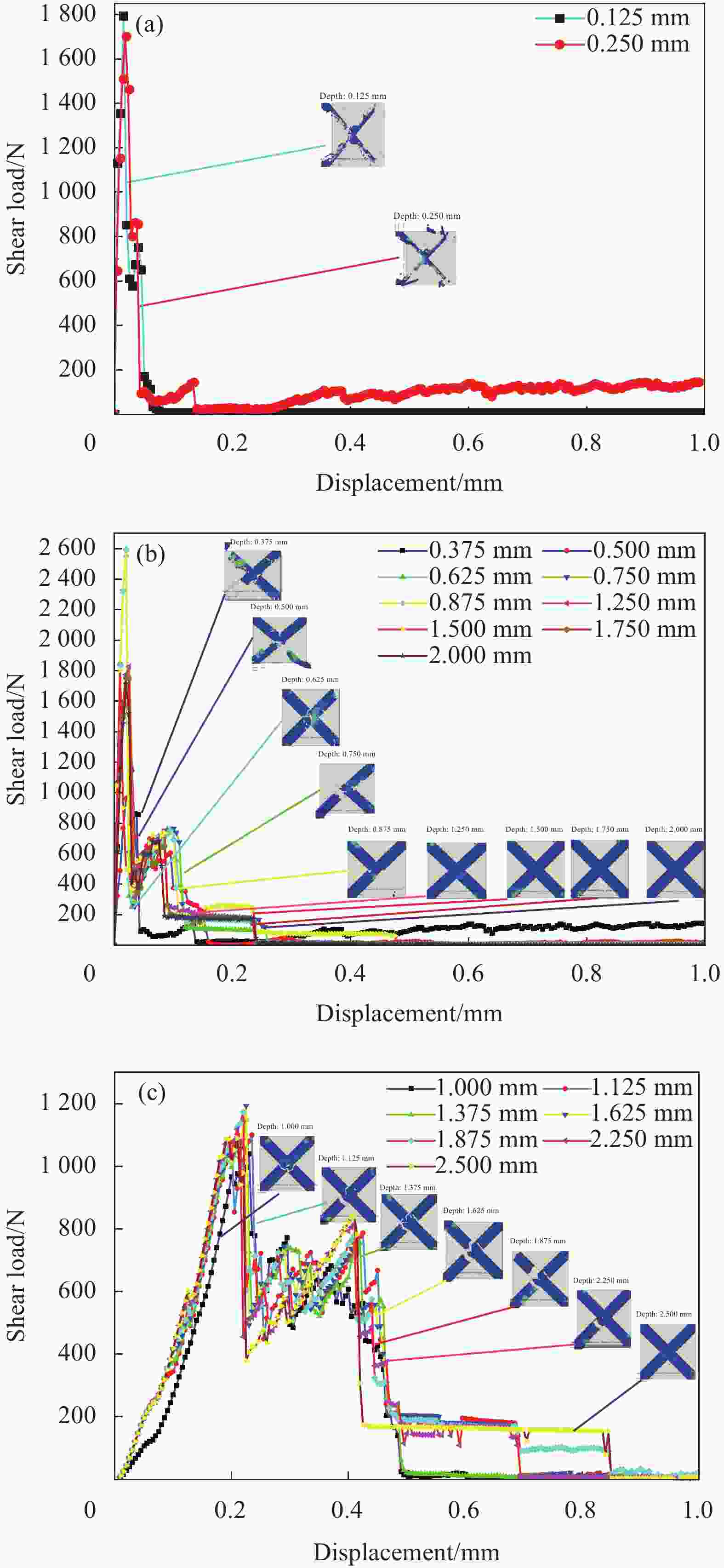
图 13 钢-GFRP接头载荷-位移曲线及模拟后金属槽内残留树脂 (RVE的边缘宽度L=1.414 mm):(a) P&D失效模式;(b) NP&PD失效模式;(c) PP&PD失效模式
Figure 13. Load-displacement curves of steel-GFRP joint and residual resin in metal grooves after simulation (Edge width of RVE L=1.414 mm): (a) P&D failure mode; (b) NP&PD failure mode; (c) PP&PD failure mode

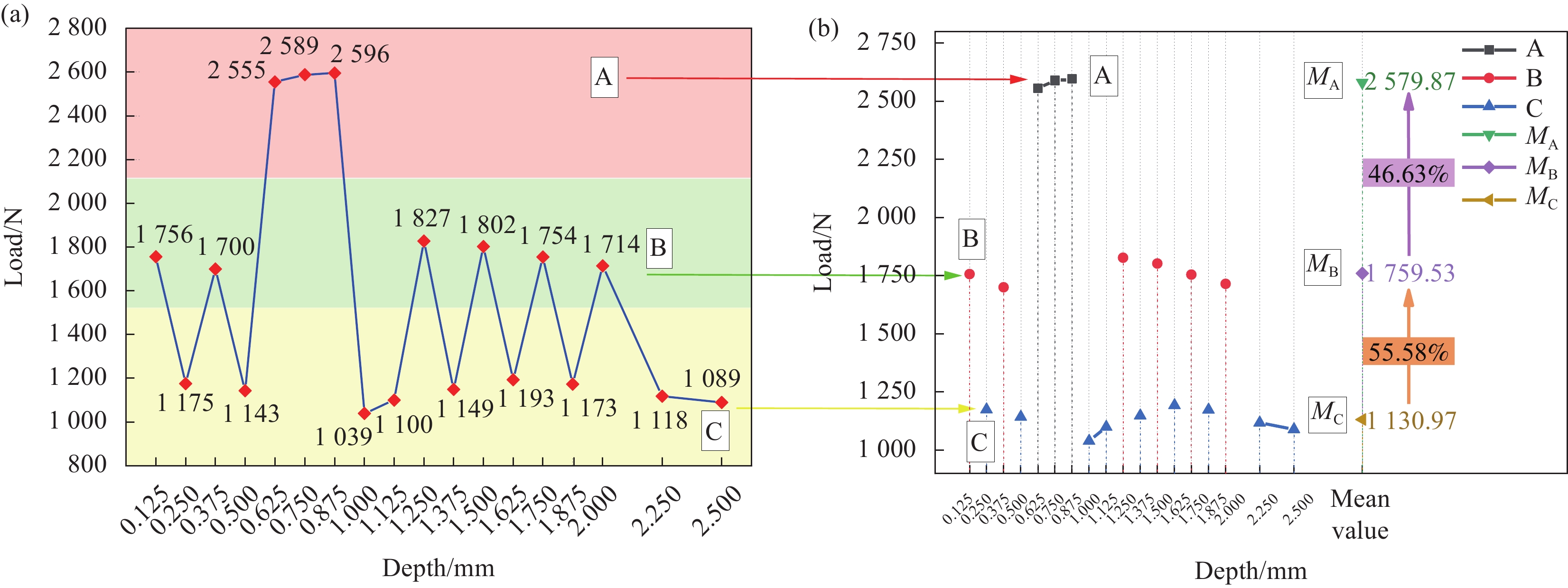
图 14 不同凹槽深度对应的钢-GFRP接头极限载荷:(a) 极限载荷折线图(按载荷值划分); (b) A、B、C数据折线图
Figure 14. Ultimate load of steel-GFRP joint corresponding to different groove depths: (a) Break-line diagram of ultimate load (Divided according to load value); (b) Break line diagram of A, B, C data
MA, MB, MC—Mean value of ultimate load of group A, B and C, respectively
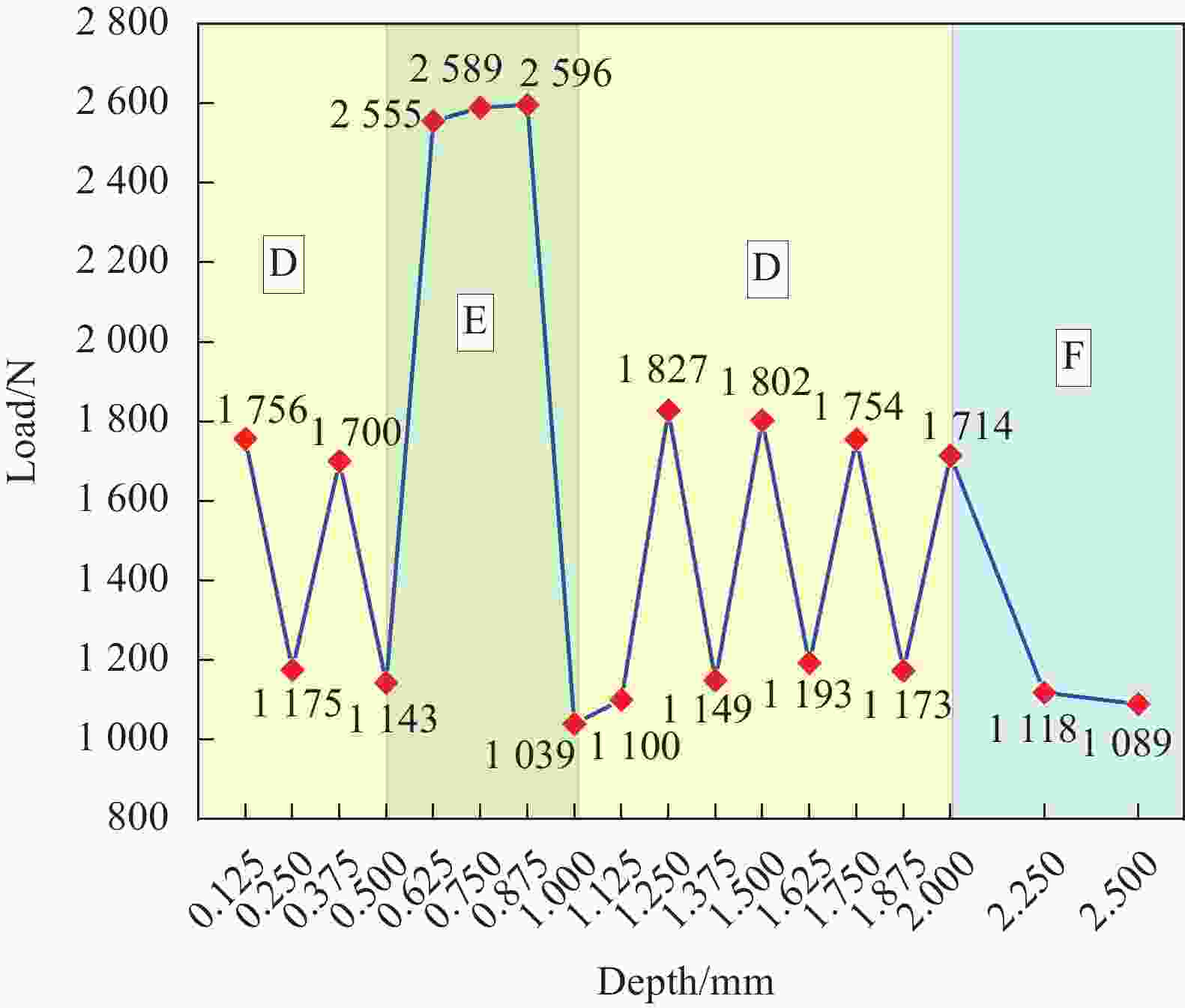
图 15 不同凹槽深度对应的钢-GFRP接头极限载荷(凹槽深度划分)
Figure 15. Ultimate load of steel-GFRP joint corresponding to different groove depths (Division of groove depth)
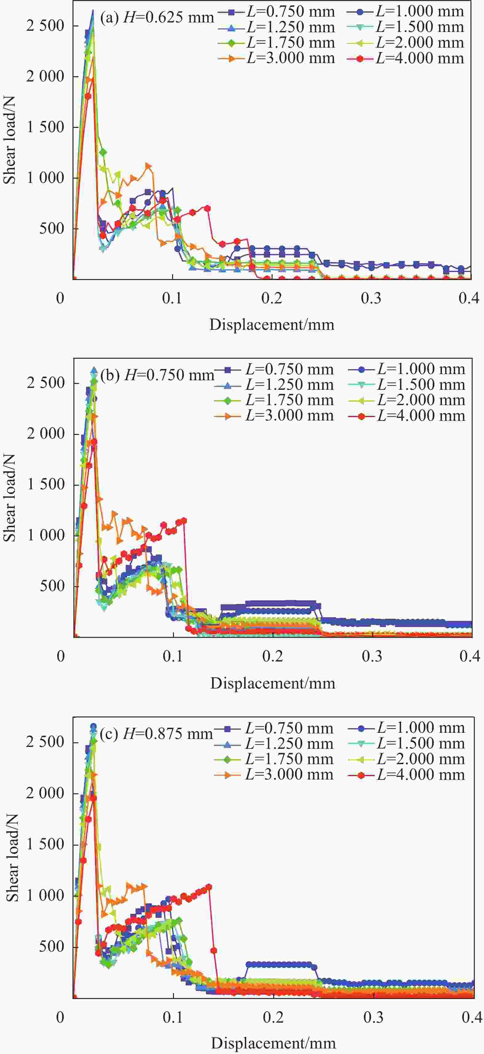
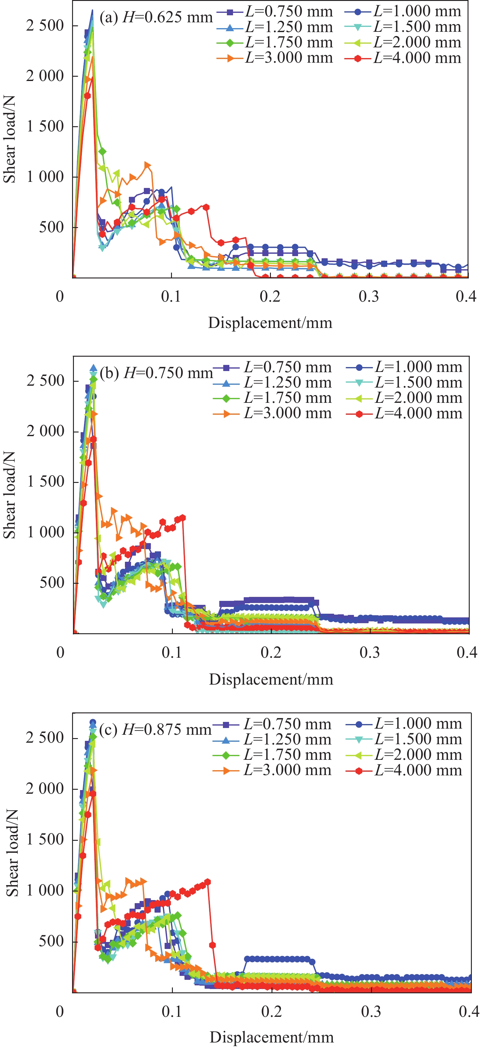
图 16 不同宽度的钢-GFRP接头载荷-位移曲线
Figure 16. Load-displacement curves of steel-GFRP joints with different widths

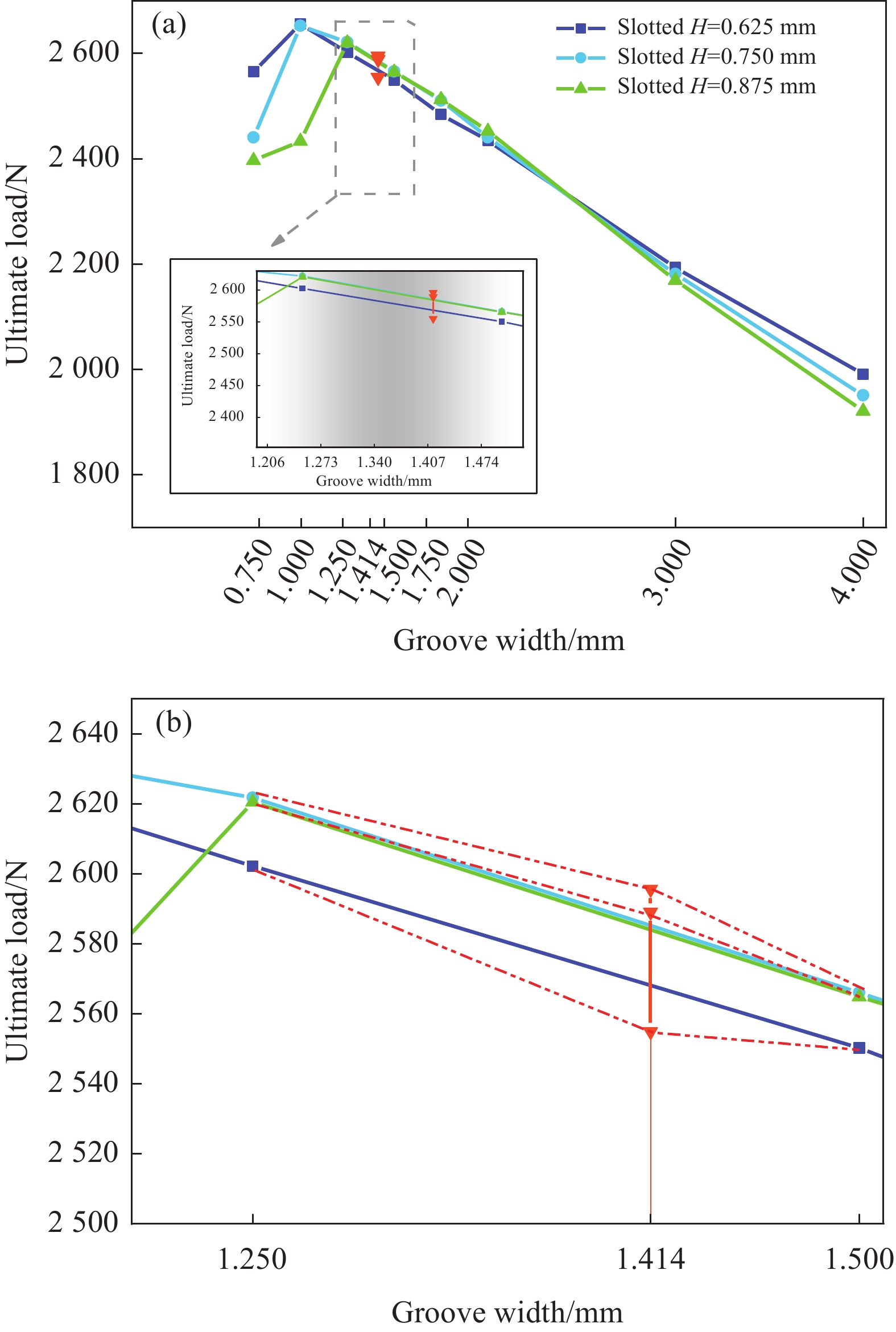
图 17 不同槽宽对应的钢-GFRP接头极限载荷:(a) 槽宽-极限载荷折线图;(b) 局部放大图
Figure 17. Ultimate load of steel-GFRP joints corresponding to different groove widths: (a) Groove width-ultimate load line graph; (b) Partially magnified graph
表 1 45#碳素结构钢基板力学性能参数
Table 1. Mechanical performance parameters of the 45# carbon structural steel substrate
Property Value Elastic modulus/GPa 210 Poisson's ratio 0.275 Density/(kg·m−3) 7900 Ultimate strength/MPa 600 Yield strength/MPa 355  下载: 导出CSV
表 2 玻璃纤维增强树脂复合材料的材料参数
Table 2. Material parameters of GFRP
Elastic modulus Value Material strength Value ${E_{11}}$/GPa 20.000 $ {X}_{\mathrm{t}} $/MPa 560 ${E_{22}}$/GPa 6.545 $ {X}_{\mathrm{c}} $/MPa 450 ${E_{33}}$/GPa 6.545 $ {Y}_{\mathrm{t}} $/MPa 10.42 ${G_{12}}$/GPa 3.545 $ {Y}_{\mathrm{c}} $/MPa 106.00 ${G_{13}}$/GPa 3.545 $ {Z}_{\mathrm{t}} $/MPa 10.42 ${G_{23}}$/GPa 1.520 $ {Z}_{\mathrm{c}} $/MPa 106.00 ${\nu _{12}}$ 0.30 $ {S}_{ 12} $/MPa 13.7 ${\nu _{13}}$ 0.30 $ {S}_{ 13} $/MPa 13.7 ${\nu _{23}}$ 0.45 $ {S}_{ 23} $/MPa 6.0 Notes: ${E_{11}}$, ${E_{22}}$ and ${E_{33}}$—Tensile moduli in the principal direction of the composite; ${G_{12}}$, ${G_{13}}$ and ${G_{23}}$—Shear moduli of the composite; ${\nu _{12}}$, ${\nu _{13}}$ and ${\nu _{23}}$—Poisson's ratios of the composite, where, 1 represents the fiber direction, 2 represents the direction perpendicular to the fiber, and 3 represents the direction perpendicular to the 1 and 2 planes; ${X_{\text{t}}}$, ${Y_{\text{t}}}$ and ${Z_{\text{t}}}$—Tensile strengths in the main direction of the composite; ${X_{\text{c}}}$, ${Y_{\text{c}}}$ and ${Z_{\text{c}}}$—Compressive strengths in the principal direction of the composite; ${S_{ 13}}$, ${S_{ 23}}$ and ${S_{ 12}}$—Shear strengths of the composites.
下载: 导出CSV
表 3 亚什兰Derakane™ 411环氧乙烯基树脂浇筑体的材料参数
Table 3. Material parameters of Ashland Derakane™ 411 epoxy-vinyl resin casting body
Property Value Tensile strength/MPa 83 Tensile modulus/GPa 2.9 Flexural strength/MPa 148 Flexural modulus/GPa 3.4 Impact strength/(kJ·m−2) 19
下载: 导出CSV
表 4 研究中所用材料性能的退化规律
Table 4. Degradation rules for the material properties used in the study
Failure mode Failure criterion Material degradation criterion Fiber tensile failure ${\sigma _{11}} \geqslant 0$ $ \begin{array}{l}E'_{11}=0.07{E}_{11}; G'_{12}=0.07{G}_{12}; G'_{13}=0.07{G}_{13}; \nu '_{12}=0.07{\nu }_{12}; \nu '_{13}=0.07{\nu }_{13}\end{array} $ Fiber compression failure ${\sigma _{11}} < 0$ $ \begin{array}{l}E'_{11}=0.07{E}_{11}; G'_{12}=0.07{G}_{12}; G'_{13}=0.07{G}_{13}; \nu '_{12}=0.07{\nu }_{12}; \nu '_{13}=0.07{\nu }_{13}\end{array} $ Matrix tensile failure ${\sigma _{22}} + {\sigma _{33}} \geqslant 0$ $ \begin{array}{l}E'_{22}=0.2{E}_{22}; G'_{12}=0.2{G}_{12}; G'_{23}=0.2{G}_{23}; \nu '_{12}=0.2{\nu }_{12}; \nu '_{23}=0.2{\nu }_{23}\end{array} $ Matrix compression failure ${\sigma _{22}} + {\sigma _{33}} < 0$ $ \begin{array}{l}E'_{22}=0.4{E}_{22}; G'_{12}=0.4{G}_{12}; G'_{23}=0.4{G}_{23}; \nu '_{12}=0.4{\nu }_{12}; \nu '_{23}=0.4{\nu }_{23}\end{array} $ Tensile delamination failure ${\sigma _{33}} \geqslant 0$ $ \begin{array}{l}E'_{33}=0.2{E}_{33}; G'_{13}=0.2{G}_{13}; G'_{23}=0.2{G}_{23}; \nu '_{13}=0.2{\nu }_{13}; \nu '_{23}=0.2{\nu }_{23}\end{array} $ Compression delamination failure ${\sigma _{33}} < 0$ $ \begin{array}{l}E'_{33}=0.2{E}_{33}; G'_{13}=0.2{G}_{13}; G'_{23}=0.2{G}_{23}; \nu '_{13}=0.2{\nu }_{13}; \nu '_{23}=0.2{\nu }_{23}\end{array} $ Notes: $E'_{11} $, $E'_{22} $ and $E'_{33} $—Tensile moduli in the principal direction of the composite after failure; $G'_{12} $, $G'_{13} $ and $G'_{23} $—Shear moduli of the composite after failure; ${{\nu '}_{12}} $, ${{\nu '}_{13}} $ and ${{\nu '}_{23}} $—Poisson's ratios of the composite after failure.
下载: 导出CSV
表 5 不同槽深钢-GFRP接头RVE结构失效模式
Table 5. Failure modes of steel-GFRP joint RVE structures with different groove depths
Depth/mm Failure mode Fig.13(a) 0.125 0.250 P&D Fig.13(b) 0.375 0.500 0.625 NP&PD 0.750 0.875 1.125 1.500 1.750 2.000 Fig.13(c) 1.000 1.125 1.375 PP&PD 1.625 1.875 2.250 2.500 − − Notes: P—Pulled out completely; D—Larger damage area; NP—Not pulled out at all; PD—Partially damaged; PP—Pulled out partially; PD—Partially destroyed.
下载: 导出CSV
-
[1] 毛振刚, 侯玉亮, 李成, 等. 搭接长度和铺层方式对CFRP复合材料层合板胶接结构连接性能和损伤行为的影响[J]. 复合材料学报, 2020, 37(1):121-131.MAO Zhen’gang, HOU Yuliang, LI Cheng, et al. Effect of lap length and stacking sequence on strength and damage behaviors of adhesively bonded CFRP composite laminates[J]. Acta Materiae Compositae Sinica,2020,37(1):121-131(in Chinese). [2] 邓雅琼, 陈洋, 栗娜, 等. 三维编织复合材料与金属胶接结构的力学性能及优化[J]. 复合材料学报, 2018, 35(10):2760-2767.DENG Yaqiong, CHEN Yang, LI Na, et al. Mechanical properties and optimization adhesive structure of three-dimensional braided composites and metal[J]. Acta Materiae Compositae Sinica,2018,35(10):2760-2767(in Chinese). [3] 段瑛涛, 武肖鹏, 王智文, 等. 碳纤维增强树脂复合材料-热成型钢超混杂层合板层间力学性能[J]. 复合材料学报, 2020, 37(10):2418-2427.DUAN Yingtao, WU Xiaopeng, WANG Zhiwen, et al. Interlaminar mechanical properties of carbon fiber reinforced plastics-thermoformed steel super-hybrid laminates[J]. Acta Materiae Compositae Sinica,2020,37(10):2418-2427(in Chinese). [4] PARK S Y, CHOI W J, CHOI H S, et al. Recent trends in surface treatment technologies for airframe adhesive bonding processing: A review (1995-2008)[J]. Journal of Adhesion,2010,86(2):192-221. doi: 10.1080/00218460903418345 [5] HE P, CHEN K, YANG J. Surface modifications of Ti alloy with tunable hierarchical structures and chemistry for improved metal-polymer interface used in deepwater composite riser[J]. Applied Surface Science,2015,328:614-622. doi: 10.1016/j.apsusc.2014.12.081 [6] CAPLAN I L. Marine composites—The US navy experience, lessons learned along the way[J]. Nist Special Publication SP,1995,887:91-114. [7] 李晓文. 舰船复合材料上层建筑连接结构设计优化研究[D]. 哈尔滨: 哈尔滨工程大学, 2017.LI Xiaowen. Research on optimization design of connection structure of ship composite superstructure [D]. Harbin: Harbin Engineering University, 2017(in Chinese). [8] DE FREITAS S T, SINKE J. Failure analysis of adhesively-bonded skin-to-stiffener joints: Metal-metal vs. composite-metal[J]. Engineering Failure Analysis,2015,56:2-13. doi: 10.1016/j.engfailanal.2015.05.023 [9] DA SILVA L F, FERREIRA N, RICHTER-TRUMMER V, et al. Effect of grooves on the strength of adhesively bonded joints[J]. International Journal of Adhesion and Adhesives,2010,30(8):735-743. doi: 10.1016/j.ijadhadh.2010.07.005 [10] MARQUES E A S, CARBAS R J C, SILVA F, et al. Use of master curves based on time-temperature superposition to predict creep failure of aluminium-glass adhesive joints[J]. International Journal of Adhesion and Adhesives,2017,74:144-154. doi: 10.1016/j.ijadhadh.2016.12.007 [11] BROCKMANN W, GEIß P L, KLINGEN J, et al. Adhesive bonding: Materials, applications and technology[M]. Weinheim Germany: John Wiley-VCH verlag GmbH & Co. KGaA, 2008. [12] DI BOON Y, JOSHI S C, ONG L S. Interfacial bonding between CFRP and mechanically-treated aluminum liner surfaces for risers[J]. Composite Structures,2018,188:374-386. doi: 10.1016/j.compstruct.2018.01.047 [13] HE P, HUANG M, FISHER S, et al. Effects of primer and annealing treatments on the shear strength between anodized Ti6Al4V and epoxy[J]. International Journal of Adhesion and Adhesives,2015,57:49-56. doi: 10.1016/j.ijadhadh.2014.10.004 [14] TAO R, ALFANO M, LUBINEAU G. Laser-based surface patterning of composite plates for improved secondary adhesive bonding[J]. Composites Part A: Applied Science and Manufacturing,2018,109:84-94. doi: 10.1016/j.compositesa.2018.02.041 [15] NGUYEN A T, BRANDT M, ORIFICI A C, et al. Hierarchical surface features for improved bonding and fracture toughness of metal-metal and metal-composite bonded joints[J]. International Journal of Adhesion and Adhesives,2016,66:81-92. doi: 10.1016/j.ijadhadh.2015.12.005 [16] FIELDEN-STEWART Z, COOPE T, BACHEVA D, et al. Effect of the surface morphology of SLM printed aluminium on the interfacial fracture toughness of metal-composite hybrid joints[J]. International Journal of Adhesion and Adhesives,2021,105:102779. doi: 10.1016/j.ijadhadh.2020.102779 [17] 陈潇凯, 符东, 孙凌玉, 等. CFRP/Al胶接接头形貌特征对连接性能影响[J]. 北京理工大学学报, 2020, 40(9):970-974.CHEN Xiaokai, FU Dong, SUN Lingyu, et al. The effect of morphology characteristics of CFRP/Al single lap joints on bonding properties[J]. Transactions of Beijing Institute of Technology,2020,40(9):970-974(in Chinese). [18] YANG G, YANG T, YUAN W, et al. The influence of surface treatment on the tensile properties of carbon fiber-reinforced epoxy composites-bonded joints[J]. Composites Part B: Engineering,2019,160:446-456. doi: 10.1016/j.compositesb.2018.12.095 [19] MOSTOFINEJAD D, MOGHADDAS A. Bond efficiency of EBR and EBROG methods in different flexural failure mechanisms of FRP strengthened RC beams[J]. Construction and Building Materials,2014,54:605-614. doi: 10.1016/j.conbuildmat.2014.01.002 [20] MOSTOFINEJAD D, MOFRAD M H, HOSSEINI A, et al. Investigating the effects of concrete compressive strength, CFRP thickness and groove depth on CFRP-concrete bond strength of EBROG joints[J]. Construction and Building Materials,2018,189:323-337. doi: 10.1016/j.conbuildmat.2018.08.203 [21] CANYURT O E, MERAN C. Fatigue strength estimation of adhesively bonded tongue and groove joint of thick woven composite sandwich structures using genetic algorithm approach[J]. International Journal of Adhesion and Adhesives,2012,33(5):80-88. doi: 10.1016/j.ijadhadh.2011.11.008 [22] CANYURT O E, MERAN C, USLU M. Strength estimation of adhesively bonded tongue and groove joint of thick composite sandwich structures using genetic algorithm approach[J]. International Journal of Adhesion and Adhesives,2010,30(5):281-287. doi: 10.1016/j.ijadhadh.2009.09.005 [23] ASTM. Standard guide for use of adhesive-bonded single lap-joint specimen test results: ASTM D4896—2001(2016)[S]. West Conshohocken: ASTM International, 2001. [24] FIORE V, DI FRANCO F, MIRANDA R, et al. Effects of anodizing surface treatment on the mechanical strength of aluminum alloy 5083 to fibre reinforced composites adhesive joints[J]. International Journal of Adhesion and Adhesives,2021,108:102868. doi: 10.1016/j.ijadhadh.2021.102868 [25] HASHIN Z. Failure criteria for unidirectional fibre composites[J]. Journal of Applied Mechanics,1980,47:329-334. doi: 10.1115/1.3153664 [26] TAN S C. A progressive failure model for composite laminates containing openings[J]. Journal of Composite Materials,1991,25(5):556-577. doi: 10.1177/002199839102500505 -

 下载:
下载:


 点击查看大图
计量
- 文章访问数: 919
- HTML全文浏览量: 537
- PDF下载量: 74
- 被引次数: 0
