

Cyclic compression behavior of FRP-ECC confined concrete cylinder
-
摘要: 考虑核心柱混凝土强度等级、碳纤维增强树脂复合材料(FRP)网格层数、反复荷载形式等因素,对FRP网格与工程水泥基复合材料(ECC)复合增强混凝土圆柱进行了轴向受压试验,研究约束圆柱的承载力和变形能力。试验结果表明,约束柱的破坏形态表现为FRP柔性网格断裂;随着网格层数的增加,约束柱的极限荷载和变形性能分别提高2%~35%和77%~145%;随着核心混凝土强度等级的提高,复合约束柱的极限承载力提高幅度降低。此外,根据试验结果并结合FRP约束混凝土的应力-应变关系模型,本文针对FRP-ECC复合约束圆柱在反复荷载作用下提出了相应的强度模型和应力-应变关系包络线模型。分析结果表明,模型所得轴向应力-轴向应变及轴向应力-环向应变关系曲线均与试验值吻合良好。Abstract: Considering the strength grade of core concrete, reinforcement layer of fiber-reinforced polymer (FRP) textile, the axial compressive tests of concrete cylinders strengthened with FRP textile and engineered cementitious composites (ECC) were carried out to study the bearing capacity and deformation performance of the FRP-ECC confined cylinder. The test results show that the failure mode of most strengthened cylinders is the rupture of embedded FRP flexible textile. With the increase of reinforcement FRP textile layers, the strengthened columns’ ultimate bearing capacity and deformation performance are improved by 2%-35% and 77%-145%, respectively. With the increase of the strength grade of the core concrete, the increase range of the ultimate bearing capacity is gradually reduced. In addition, according to the test results and the stress-strain model of FRP confined concrete, the corresponding strength model and envelope stress-strain models of FRP-ECC confined cylinder are given. The analysis results show that the stress-strain curves predicted by these models match well with test results.
-
Keywords:
- cyclic loading /
- FRP textile /
- ECC /
- confined cylinder /
- stress-strain model /
- concrete cylinder
-
熔模精密铸造广泛应用于航空航天关键零部件生产,特别是在高熔炼温度,高化学活性金属的成形中起着不可替代的作用,如发动机高温合金涡轮叶片、导向叶片、叶轮和机匣等[1]。一般地,陶瓷型壳由耐火材料和粘结剂逐层覆盖在蜡模表面制备,于脱蜡后形成复杂内腔,用以构建铸件主体与外轮廓[2]。因此,要求型壳具备良好的湿(生坯)强度防止脱蜡及搬运造成破裂,较高的烧结强度以抵御浇注熔体作用力,足够的透气性便于型腔气体逸出和理想的抗蠕变性确保铸件尺寸精度[1, 3]。但是,型壳的强度和孔隙率之间存在相互制约的关系,通过增加厚度提升型壳承载能力,将引起型壳透气性差、散热困难,致使铸件晶粒粗大、表面缺陷加剧[4]。为此,国内外学者就耐火材料种类[5]、粒度级配[6]、粘结剂[7]、焙烧制度[1, 8]、矿化剂[9]等方面进行了深入讨论与研究。然而,高性能熔模精铸陶瓷型壳制备及改性,尤其是上述对立性能的平衡与优化仍然是亟待解决的问题[1, 4]。
Jones等[10]率先提出以纤维材料改性型壳,在硅溶胶浆料中引入短切尼龙纤维(Nsf)显著增加了单次挂壳厚度,提升了型壳锐边抗裂能力。同期,Yuan等[11]指出Nsf烧失形成连通孔隙大幅度改善了型壳透气性。类似地,Pattnaik的研究表明0.6wt%植物椰壳纤维改性型壳获得28.43%开气孔率,透气性显著增加[12]。Lv等[13]制备了天然香蒲纤维增强锆英石-莫来石硅溶胶型壳,发现含有1.0wt%纤维型壳的湿强度相较于无纤维型壳提升44%,而在纤维含量为0.6wt%时取得烧结强度最大值为4.6 MPa。Huang等[14]对Nsf增强刚玉系硅溶胶型壳的研究指出型壳烧结强度随纤维含量先增后减少,过量纤维烧失将造成烧结强度的牺牲。文献表明[14-15],陶瓷纤维和玻璃纤维改性型壳在煅烧后,纤维仍然保留于基体起到强化作用,型壳分别增强至5.08 MPa和5.92 MPa。上述研究基于界面脱粘、应力再分布、纤维拔出等机制证实纤维可有效强化型壳强度[3, 16]。综合两类纤维材料的应用优势,有机-无机混杂纤维改性型壳的报道相继出现。例如,芦苇-硅酸铝纤维[17]、尼龙-陶瓷纤维[18]、聚丙烯-硅酸铝纤维[16]、尼龙-碳纤维[3]。混杂纤维引入有效克服了硅溶胶型壳强度和透气性对立性,实现了性能的协同提升。
高极性、低润湿性的短切纤维在溶液均匀分散相当困难,受静电力或范德华力作用的纤维极易发生团聚[19]。芦刚等[20]通过超声振荡和机械搅拌的协同处理Nsf改性硅溶胶,羟丙基甲基纤维素(HPMC)加入明显提高纤维分散均匀性。过多HPMC会增加浆料悬浮性和黏度,降低浆料可操作性并减少型壳强度[21]。为确保型壳内纤维分布均匀性,相关研究[3, 10, 12-14, 16, 21]中纤维加入量一般不超过1.0wt%(纤维与浆料中耐火粉料质量比)。由于型壳是浆料层与撒砂层逐层堆叠构筑,意味着纤维在型壳整体的占比远小于1.0wt%。因此,理论上在撒砂层构筑立体纤维网络是提升强化效果的可行途径。Lv等[22]采用手工搅拌方法在锆英砂中混入0.5wt%碳纤维制备型壳,但杂乱分布的簇状纤维束易成为断裂源,强度反而低于浆料纤维改性样品。撒砂层纤维改性型壳强化也建立纤维均匀分散基础上,现有搅拌或球磨等混合方法,尚且无法获得理想砂料。
本文采用“溶剂法”将Nsf和短切氧化铝纤维(Asf)均匀掺入刚玉砂,制备撒砂层Nsf-Asf混杂纤维改性硅溶胶型壳。研究Nsf和Asf质量比对型壳性能的影响,基于SEM分析纤维和基体微观结构演变和断裂特征,揭示其强化机制对进一步优化纤维改性精铸型壳性能,发挥纤维在型壳中的应用潜力有一定意义。
1. 实验材料及方法
1.1 原材料
主要材料包括进口锆英粉、郑州海旭磨料有限公司刚玉粉/砂,山东济南银丰硅制品有限责任公司硅溶胶。其中硅溶胶含29wt%~31wt% SiO2,胶体粒径约为78 nm,pH介于9~10。面层浆料采用45 μm锆英粉,其他层浆料耐火粉料为50 μm刚玉粉。180 μm刚玉砂用以面层撒砂,过渡层撒砂使用300 μm刚玉砂,背层撒砂为700 μm刚玉砂。Nsf(ρ=1.16 g·cm−3)及Asf(ρ=1.85 g·cm−3)长度均为4 mm分别由北京融信通科技有限公司和淄博华岩耐火纤维有限公司生产。
1.2 试样制备
市售Nsf和Asf多次洗涤过滤后备用。配制硅烷偶联剂乙醇溶液并滴入少量醋酸促进水解,称取不同质量(Nsf∶Asf=4∶1、3∶2、1∶1、2∶3、1∶4)混杂纤维浸入烧杯进行纤维表面处理。处理后混杂纤维经过滤干燥,加入0.2wt%~0.3wt%的HPMC乙醇溶液中,施加超声振荡至均匀分散。少量多次加入刚玉砂,持续机械搅拌直至砂粒呈悬浊状态。过滤蒸干后获得不同质量比混杂纤维刚玉砂待用,实物图由图1可见,其制备参数如表1所示。采用Nsf-Asf混杂纤维改性硅溶胶浆料进行挂壳,混杂纤维改性硅溶胶浆料制备方法可见于已报道的工作[3, 18],本研究涉及的浆料参数如表2所示,涂挂后手工撒上混杂纤维刚玉砂。溶剂法制备混杂纤维刚玉砂及撒砂制壳流程示意图如图2所示。型壳干燥温度为22~26℃,环境湿度介于40%~70%,面层及过渡层干燥12 h,其他层干燥24 h。采用DRTF蒸汽脱蜡釜(东营市硕纬机械有限公司)脱除蜡模,获得生坯型壳,PD-MJ10马弗炉(洛阳高新开发区蓬达窑炉厂)内焙烧型壳,阶梯式烧成制度如图3所示。
![]() 图 1 不同质量比短切尼龙纤维(Nsf)-氧化铝纤维(Asf)混杂纤维刚玉砂实物图Figure 1. Real images of corundum sands with hort nylon fiber (Nsf)- short alumina fiber (Asf) hybrid fibers in different fiber mass ratios表 1 混杂纤维刚玉砂制备参数Table 1. Preparation details of hybrid fibers modified corundum sands
图 1 不同质量比短切尼龙纤维(Nsf)-氧化铝纤维(Asf)混杂纤维刚玉砂实物图Figure 1. Real images of corundum sands with hort nylon fiber (Nsf)- short alumina fiber (Asf) hybrid fibers in different fiber mass ratios表 1 混杂纤维刚玉砂制备参数Table 1. Preparation details of hybrid fibers modified corundum sandsStuccoing layers Corundum size/μm Mass ratios (Nsf∶Asf) Hybrid fiber content String time/h Primary layer 180 4∶1, 3∶2, 1∶1, 2∶3, 1∶4 0.75wt% of sands 6 Translation layer 300 9 Back layer 700 12 表 2 混杂纤维改性硅溶胶型壳浆料制备参数Table 2. Preparation details of slurry for modified silica sol ceramic shellSmearing layers Filler/μm Binder Filler∶binder/
(g·mL−1)Fiber type Hybrid fiber content Additive Primary layer Zirconium (45) Silica sol 3.03∶1 None fiber None fiber JFC wetting agent (0.2wt%-0.3wt%) and antifoaming
agent (0.3wt%-0.5wt%)Translation layer Corundum (50) 1.5∶1 4 mm Nsf and
Asf at a mass
ratio of 3∶20.6wt% of
fillersBack layer Seal layer 2.26∶1 Note: JFC—fatty alcohol-polyoxyethylene ether. ![]() 图 2 溶剂法获得Nsf-Asf混杂纤维刚玉砂并制备改性硅溶胶型壳示意图Figure 2. Preparation details of solvent method for Nsf-Asf hybrid fibers corundum sands and the modified silica sol ceramic shellHPMC—Hydroxypropyl methyl cellulose
图 2 溶剂法获得Nsf-Asf混杂纤维刚玉砂并制备改性硅溶胶型壳示意图Figure 2. Preparation details of solvent method for Nsf-Asf hybrid fibers corundum sands and the modified silica sol ceramic shellHPMC—Hydroxypropyl methyl cellulose![]() 图 3 撒砂层Nsf-Asf混杂纤维改性硅溶胶型壳烧成温度制度Figure 3. Sintering temperature system of stuccoing layer Nsf-Asf hybrid fibers modified silica sol ceramic shell
图 3 撒砂层Nsf-Asf混杂纤维改性硅溶胶型壳烧成温度制度Figure 3. Sintering temperature system of stuccoing layer Nsf-Asf hybrid fibers modified silica sol ceramic shell1.3 测试分析
通过ZTY智能型砂型测试仪(无锡天牧仪器科技有限公司),测定煅烧型壳透气性[18],试样尺寸为直径Φ50 mm×5 mm,以阿基米德排水法测量该样品开气孔率,计算公式如下:
O=M3−M1M3−M2×100% (1) 其中:
O 为开气孔率;M1 为试样质量;M2 为水中试样质量;M3为擦干后试样质量。采用SWY液压万能强度实验机(北京同德创业科技有限公司),以三点抗弯法获得型壳湿强度及烧结强度,样品尺寸为40 mm×20 mm×6 mm,计算公式如下:σf=3PL2bW2 (2) 其中:
σf 为样品抗弯强度(MPa);P 为最大应力(N);L 、b 和W 分别为跨距、样品宽度和高度(mm)。强度数据取5根样品平均值,并计算标准差。高温自重变形率初始样品直径为100 mm,厚度为20 mm的圆环状型壳,放置到1350℃马弗炉内加热0.5 h,冷却到300℃时取出测量其尺寸,计算公式如下:δt−τ=A−BB×100% (3) 其中:
δt−τ 为高温自重变形率(%);A 、B 分别为加热前后样品直径(mm)。采用美国FEI公司的Quanta200型扫描电镜观察试样三点抗弯试验后断口形貌,加速电压为20 kV。2. 结果与分析
2.1 型壳断口形貌及烧结演变特征
图4为Nsf-Asf混杂纤维改性型壳生坯断口SEM图像。可见,型壳断面凹凸不平,基体组织疏松,细小陶瓷粉料填充粗大刚玉砂粒间隙,部分粉粒因硅溶胶粘结,附着于砂粒表面。随着Nsf占比的下降,视场内可视纤维数量逐渐增加。如图4(a)、图4(b)所示,拔出纤维垂直于断面均匀分布,而在图4(d)中,纤维明显团聚。簇状纤维取代刚玉砂间陶瓷浆料,降低了纤维与基体实际接触面积,同时,相较于其他样品其纤维拔出长度锐减。
![]() 图 4 不同质量比撒砂层Nsf-Asf混杂纤维改性型壳生坯断口SEM图像:(a) 4∶1;(b) 3∶2;(c) 2∶3;(d) 1∶4Figure 4. SEM images of green body for stuccoing layer Nsf-Asf hybrid fibers modified silica sol ceramic shell with different fiber mass ratios: (a) 4∶1; (b) 3∶2; (c) 2∶3; (d) 1∶4
图 4 不同质量比撒砂层Nsf-Asf混杂纤维改性型壳生坯断口SEM图像:(a) 4∶1;(b) 3∶2;(c) 2∶3;(d) 1∶4Figure 4. SEM images of green body for stuccoing layer Nsf-Asf hybrid fibers modified silica sol ceramic shell with different fiber mass ratios: (a) 4∶1; (b) 3∶2; (c) 2∶3; (d) 1∶4图5为煅烧型壳断口形貌。如图5(a)、图5(b)所示,较粗Nsf完全烧失形成原位长孔而较细的Asf完整保留在型壳基体。焙烧过程中,粘结剂中水分和残余有机物气化脱除,型壳不断干燥,耐火粉体间黏附力下降,陶瓷颗粒持续收缩,张力不足时浆料连接区萌生微裂纹(图5(c))。陶瓷材料的煅烧是生坯颗粒比表面积降低的低能晶界代替高能晶界过程[23]。随温度升高,硅溶胶中SiO2质点优先受热作用激活发生扩散迁移,构成立体玻璃骨架连接基体陶瓷颗粒。随机附着于刚玉砂表层的高表面能粉体,晶格内原子重排加速并向表层运动,引起粉体体积生长,晶界孔隙缩小。因此,型壳强度主要由颗粒/颗粒或颗粒/Asf界面连接层提供,故如同图4(c)所示,样品呈典型沿晶断裂特征。由于型壳终烧温度仅950℃,大尺寸刚玉颗粒及残留Asf均未发生变形(图5(c)、图5(d)),良好地保证了型壳尺寸稳定。
![]() 图 5 不同质量比撒砂层Nsf-Asf混杂纤维改性型壳煅烧样品断口SEM图像:(a) 4∶1;(b) 3∶2;(c) 2∶3;(d) 1∶4Figure 5. SEM images of sintering body for stuccoing layer Nsf-Asf hybrid fibers modified ceramic shell with different fiber mass ratios: (a) 4∶1; (b) 3∶2; (c) 2∶3; (d) 1∶4d—Distance
图 5 不同质量比撒砂层Nsf-Asf混杂纤维改性型壳煅烧样品断口SEM图像:(a) 4∶1;(b) 3∶2;(c) 2∶3;(d) 1∶4Figure 5. SEM images of sintering body for stuccoing layer Nsf-Asf hybrid fibers modified ceramic shell with different fiber mass ratios: (a) 4∶1; (b) 3∶2; (c) 2∶3; (d) 1∶4d—Distance需要指出的是,Nsf与Asf长度均为4 mm,密度比约为0.627,直径比约1.776,即等质量Asf在数量上约是Nsf的两倍。当Nsf占比减少,Asf上升时,溶剂内纤维实际数量增加,纤维缠绕概率增大[14]。此外,对比图5(d)纤维数量可进一步证实图4(d)中簇状纤维为分散不足导致。同理,对比图5(a)中单丝Nsf烧失孔,图5(d)中的超尺寸孔隙归因于交织Nsf。
2.2 混杂纤维质量比对型壳孔隙和高温变形的影响
图6为撒砂层Nsf-Asf混杂纤维质量比对型壳透气性及开气孔率的影响。可知,Nsf∶Asf=4∶1样品透气性和气孔率最高,分别为4.4、20.80%。随着Nsf占比下降,型壳透气性和开气孔率持续减小,性能最差的Nsf∶Asf=1∶4样品为2.6、18.96%。型壳透气性与开气孔率有直接关联性,二者保持近似衰减趋势,但下降幅度差异较大分别约50%、8.96%。Nsf纤维的烧失直接在型壳基体内造孔,Nsf占比降低是下降的主要原因。此外,由图5可见,焙烧后Asf纤维并未与型壳基体完全贴合。Asf表面与刚玉砂粒之间存在界面间隙,证实Asf可连通型壳基体内孤立闭气孔。Nsf占比下降的同时,型壳内纤维单丝数量上升,意味着Asf/砂粒界面间隙数量增加,弥补了烧失Nsf原位孔隙减少引起的开气孔率降低。交织的烧失Nsf孔隙网络(图5(a))允许加压气体直接透过型壳。然而,Asf/砂粒界面间隙分布弥散、尺寸较小,故气体传输路径长,阻力也更大,因此Asf对型壳透气性的增益相对微弱。
![]() 图 6 撒砂层Nsf-Asf混杂纤维质量比对型壳透气性及开气孔率的影响Figure 6. Effects of fiber mass ratios on the permeability and open porosity for stuccoing layer Nsf-Asf hybrid fibers modified ceramic shell
图 6 撒砂层Nsf-Asf混杂纤维质量比对型壳透气性及开气孔率的影响Figure 6. Effects of fiber mass ratios on the permeability and open porosity for stuccoing layer Nsf-Asf hybrid fibers modified ceramic shell图7为撒砂层Nsf-Asf混杂纤维质量比对型壳高温自重变形率的影响。该性能指标即型壳高温下的蠕变特性。可以看出,随Nsf占比下降,蠕变程度先减小后增大,Nsf∶Asf=2∶3样品高温自重变形率最低为0.81%,增幅达35.2%。陶瓷坯体的蠕变破坏受基体孔洞扩展连通控制,流入孔洞或晶界间的黏滞相将引起材料整体尺寸变化[24]。因此过多烧失Nsf孔隙对型壳高温变形是有害的。Jones[25]研究指出,高温下SiO2玻璃相黏性流动是导致型壳高温蠕变的主要原因。文献[26-27]表明,无定形非晶相黏性流动易被高熔点高荷重软化点物质扰乱。Asf熔点远高于1300℃,故基体内立体互锁Asf网络有效抑制了型壳玻璃相骨架软化,阻碍SiO2黏滞相向大尺寸烧失Nsf孔隙填充。然而,刚玉砂粒间的局部簇状Nsf或Asf会割裂型壳,这些不均匀结构对型壳高温下的尺寸稳定性是不利的。因此,Nsf∶Asf=1∶4样品蠕变加剧,下降18.52%。
![]() 图 7 撒砂层Nsf-Asf混杂纤维质量比对型壳高温自重变形率的影响Figure 7. Effects of fiber mass ratios on the high temperature self-loaded deflection rate for stuccoing layer Nsf-Asf hybrid fibers modified ceramic shell
图 7 撒砂层Nsf-Asf混杂纤维质量比对型壳高温自重变形率的影响Figure 7. Effects of fiber mass ratios on the high temperature self-loaded deflection rate for stuccoing layer Nsf-Asf hybrid fibers modified ceramic shell2.3 混杂纤维质量比对型壳强度的影响及其强化机制
图8为撒砂层Nsf-Asf混杂纤维质量比对型壳湿强度和烧结强度的影响。随Nsf占比下降,湿强度由5.08 MPa下降至4.31 MPa,烧结强度先增加后降低,Nsf∶Asf=2∶3样品最高烧结强度达10.54 MPa。图9为浆料层、撒砂层纤维改性及典型硅溶胶型壳湿强度及烧结强度性能对比图(焙烧温度约为950℃)。如图9所示,有机纤维改性硅溶胶型壳湿强度显著提升[12, 14, 28],而无机纤维对型壳的烧结强度增强效果明显[14, 29-30]。由于有机纤维造孔有利于型壳透气,混杂纤维改性型壳被开发出以补偿焙烧后强度的损失,样品强度介于两类单一纤维改性型壳之间[3, 16-18, 31]。值得注意的是,上述改性型壳中,纤维引入均通过浆料的涂挂,而纤维含量则依据纤维与填料质量比或纤维质量与硅溶胶体积比。通过纤维混合硅溶胶浆料制备型壳,纤维不可避免地集中在浆料层,未能实现对型壳整体强化。因此,本文中撒砂层引入纤维并结合纤维混合硅溶胶浆料制备型壳,纤维实际体积占比增加,其烧结强度提升近一倍于浆料涂挂[32-36](图9)。
![]() 图 8 撒砂层Nsf-Asf混杂纤维质量比对型壳湿强度及烧结强度的影响Figure 8. Effects of fiber mass ratios on the green and sintering strength for stuccoing layer Nsf-Asf hybrid fibers modified ceramic shell
图 8 撒砂层Nsf-Asf混杂纤维质量比对型壳湿强度及烧结强度的影响Figure 8. Effects of fiber mass ratios on the green and sintering strength for stuccoing layer Nsf-Asf hybrid fibers modified ceramic shell![]() 图 9 浆料层、撒砂层纤维改性及典型硅溶胶型壳湿强度及烧结强度性能对比图Figure 9. Comparison charts of green and sintering strength between stuccoing layer fiber modified silica sol ceramic shell in the current study and typical shell as well as slurry layer fiber modified shell
图 9 浆料层、撒砂层纤维改性及典型硅溶胶型壳湿强度及烧结强度性能对比图Figure 9. Comparison charts of green and sintering strength between stuccoing layer fiber modified silica sol ceramic shell in the current study and typical shell as well as slurry layer fiber modified shell图10为撒砂层Nsf-Asf混杂纤维改性型壳生坯断裂实物图。可知,型壳断面上存在大量拔出纤维,Nsf∶Asf=4∶1样品裂纹呈曲线形,而Nsf∶Asf=3∶2样品中出现宏观裂纹分支(图10(b)),但随着Nsf占比下降,裂纹逐渐平直化。众所周知,纤维增强复合材料强化效果与纤维/基体界面结合强度及接触面积有关。早期纤维改性型研究中观察到,较短的陶瓷纤维(长度约1~2 mm)与硅溶胶凝胶界面及耐火材料接触较小时,纤维易与基体脱粘,裂纹向周围损伤区扩展[29]。类似地,Lv等[22]在碳纤维改性型壳研究中也指出,因纤维拔出摩擦路径延长,型壳湿强度随纤维长度增加而上升。
![]() 图 10 不同质量比撒砂层Nsf-Asf混杂纤维改性型壳生坯三点抗弯断裂实物图:(a) 4∶1;(b) 3∶2;(c) 1∶1;(d) 2∶3;(e) 1∶4Figure 10. Real fracture images of green body for stuccoing layer Nsf-Asf hybrid fibers modified ceramic shell with different fiber mass ratios after three-point bending test: (a) 4∶1; (b) 3∶2; (c) 1∶1; (d) 2∶3; (e) 1∶4
图 10 不同质量比撒砂层Nsf-Asf混杂纤维改性型壳生坯三点抗弯断裂实物图:(a) 4∶1;(b) 3∶2;(c) 1∶1;(d) 2∶3;(e) 1∶4Figure 10. Real fracture images of green body for stuccoing layer Nsf-Asf hybrid fibers modified ceramic shell with different fiber mass ratios after three-point bending test: (a) 4∶1; (b) 3∶2; (c) 1∶1; (d) 2∶3; (e) 1∶4本文中,Nsf占比下降意味刚玉砂中纤维单丝数量上升,纤维/基体理论界面面积增加。但型壳断口纤维数量及湿强度均呈下降趋势,说明撒砂层Asf对型壳湿强度的影响极其微弱。由于型壳耐火材料附着依赖重力堆积和硅溶胶黏附,撒砂层内刚玉砂粒粒径较大,故型壳撒砂层是天然疏松的。刚性纤维Asf主要分布在陶瓷颗粒间隙,与基体界面结合较弱,Asf不能以纤维拔出的方式强化生坯型壳。而Nsf具有一定柔韧性,易缠绕附着在砂粒表面,在型壳承载断裂过程,Nsf能产生有效摩擦耗能作用。
为进一步揭示焙烧后撒砂层Nsf-Asf混杂纤维改性型壳断裂机制,含典型断裂特征SEM如图11所示。如图11(a)所示,型壳制备过程基体中已形成的微裂纹在承载时不断生长,在无纤维区域形成连续裂纹,并朝向刚玉砂粒扩展,引起砂粒的整体剥离,最终导致型壳断裂。然而,煅烧过程刚玉砂间隙粉体颗粒生长与晶界孔隙缩小,如图5(b)、5(c)可见,Asf与基体结合不断紧密化。当裂纹尖端生长至纤维表面时,由于纤维本身强度较高,裂纹无法直接破坏纤维。首先,受Asf阻碍,裂纹尖端的应力分叉,随后裂纹在纤维表面沿轴向偏转,同时伴随纤维-基体界面脱粘及微裂纹增殖(图11(b))。对于某Asf单丝,当裂纹扩展至纤维末端时,界面结合较弱的一侧纤维完全与基体脱粘,发生纤维拔出直至脱离型壳断面。然而,当该Asf两端均形存在较强的结合界面,即便型壳发生宏观断裂,仍可以纤维桥接的方式连接两侧断裂型壳(图11(c))。互锁Asf网络结构有效抑制大范围的刚玉砂粒剥离,型壳由原先沿晶断裂转为包含裂纹分叉、偏转、增殖及纤维拔出和桥连的混合断裂模式。
![]() 图 11 含典型断裂特征的撒砂层Nsf-Asf混杂纤维改性型壳煅烧样品高倍SEM图像Figure 11. High magnification SEM images of sintering body for stuccoing layer Nsf-Asf hybrid fibers modified ceramic shell with type fracture characteristics
图 11 含典型断裂特征的撒砂层Nsf-Asf混杂纤维改性型壳煅烧样品高倍SEM图像Figure 11. High magnification SEM images of sintering body for stuccoing layer Nsf-Asf hybrid fibers modified ceramic shell with type fracture characteristics3. 结 论
(1) 型壳透气性主要依赖烧失短切尼龙纤维(Nsf)连通孔隙,氧化铝纤维(Asf)/基体界面间隙有利于补偿开气孔率损失,但对透气性影响不大。质量比Nsf∶Asf=4∶1的样品获得最佳透气性和开气孔率,分别为4.4、20.80%。立体互锁Asf网络抑制型壳玻璃相骨架软化,阻碍SiO2黏滞相向烧失Nsf孔隙填充。Nsf∶Asf=2∶3样品高温自重变形率仅0.81%。
(2) 生坯型壳撒砂层堆积疏松,纤维/基体界面结合弱,刚性Asf对型壳湿强度影响较小,而柔性Nsf可缠绕刚玉砂通过纤维拔出摩擦耗散载荷能量,强化生坯型壳,Nsf∶Asf=4∶1样品宏观裂纹呈曲线形,湿强度达5.08 MPa。
(3) 大尺寸孔隙或团聚簇状纤维易成为煅烧型壳断裂源。型壳基体内Asf有效抑制连续裂纹生长,阻碍基体刚玉砂粒剥离,原沿晶断裂型壳呈裂纹分叉、偏转、增殖及纤维拔出和桥连的混合断裂特征。当Nsf∶Asf=2∶3时,撒砂层混杂纤维改性型壳烧结强度高达10.54 MPa。
-
![]()
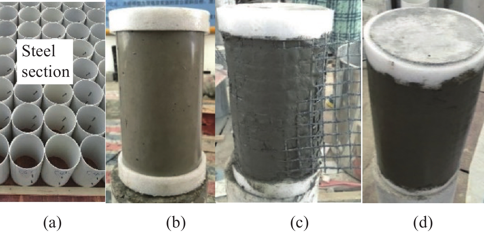
图 3 圆柱增强过程:(a) 模具;(b) 预处理;(c) 缠网格;(d) 增强柱
Figure 3. Strengthening of cylinder: (a) Mould; (b) Pretreatment; (c) Wrapping textile; (d) Strengthening cylinder
![]()
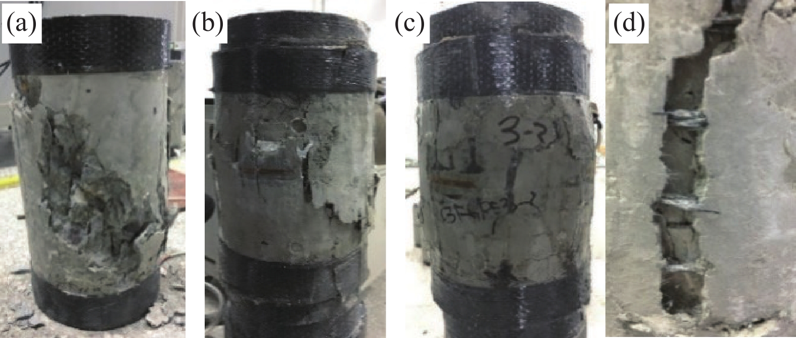
图 5 CFRP-ECC复合约束混凝土圆柱破坏形态:(a) 无约束柱;(b) 2层增强;(c) 3层增强;(d) 主裂缝
Figure 5. Failure mode of CFRP-ECC confined column: (a) Unconfined column; (b) 2 layers strengthening; (c) 3 layers strengthening; (d) Main crack
![]()
图 6 CFRP-ECC复合约束混凝土圆柱荷载-位移曲线
Figure 6. Load-deformation curves of CFRP-ECC confined column
![]()
图 7 CFRP-ECC复合约束混凝土圆柱应力-应变曲线
εc—Axial compressive strain; εl—Lateral strain
Figure 7. Stress-strain curves of CFRP-ECC confined column
![]()
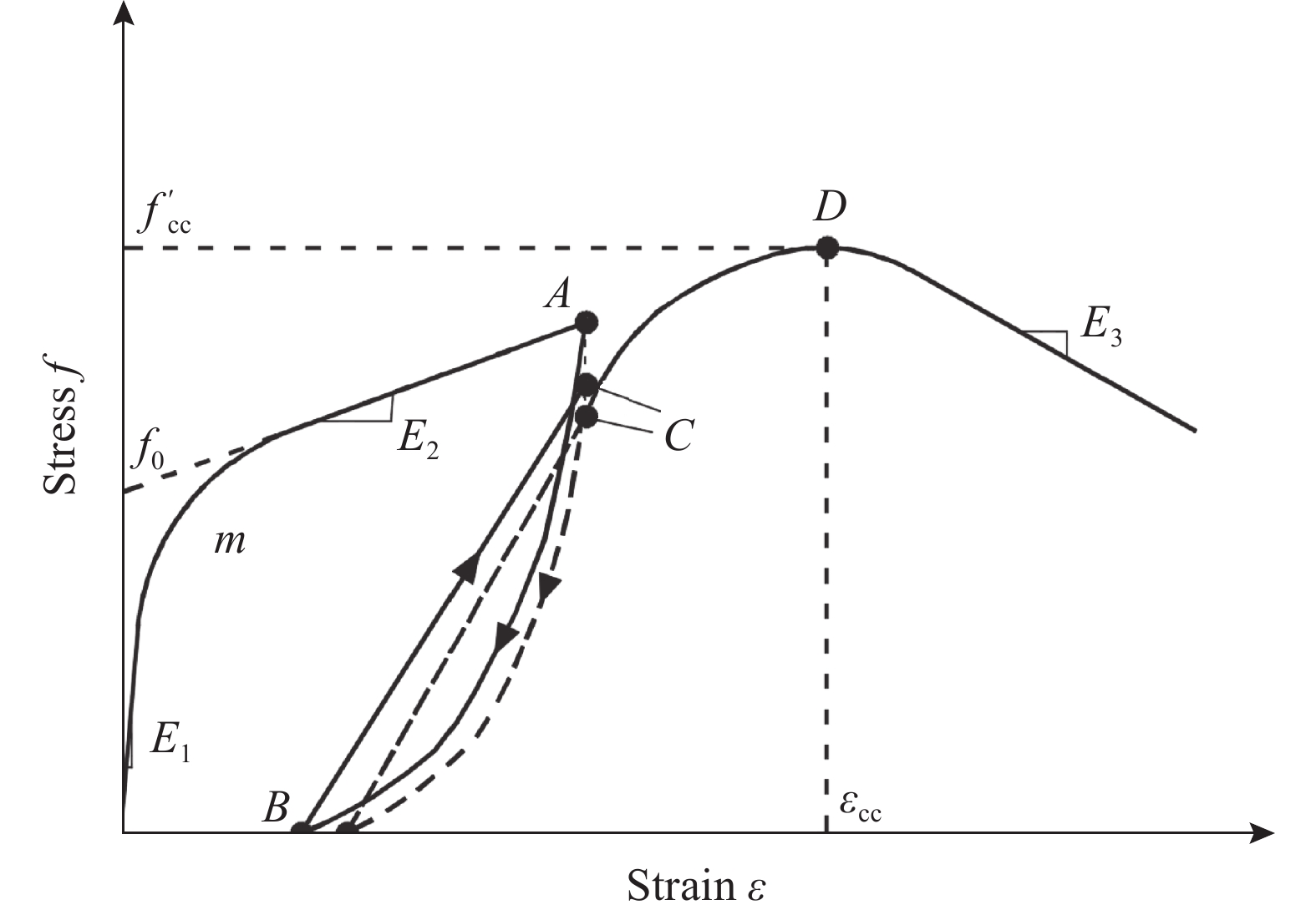
图 8 CFRP-ECC复合约束混凝土圆柱应力-应变关系
A, B, C, D—Reference points; E1, E2, E3—Slope at each stage of the curve; m—Curvature parameter; fcc' and εcc—Ultimate strength and strain; f0—Intercept stress
Figure 8. Stress-strain relationship of CFRP-ECC confined column
![]()
图 9 CFRP-ECC复合约束混凝土圆柱极限应力/应变分析
Figure 9. Analysis of CFRP-ECC confined cylinders’ ultimate stress/strain
![]()
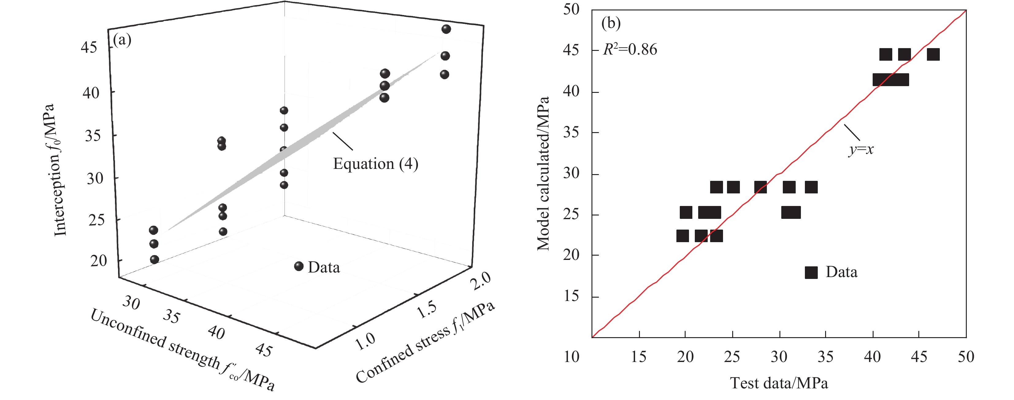
图 10 CFRP-ECC复合约束混凝土圆柱截距应力及模型-试验对比
Figure 10. Intercept stress of CFRP-ECC confined cylinders and model-test comparsion
![]()
图 11 CFRP-ECC复合约束混凝土圆柱峰值后曲线斜率发展规律及模型-试验对比
Figure 11. Relationship of post-peak curve slope of CFRP-ECC confined cylinders and model-test comparsion
![]()
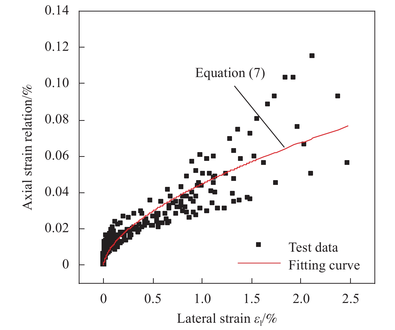
图 12 CFRP-ECC复合约束混凝土圆柱轴向-环向应变关系
Figure 12. Axial-lateral strain relationship of CFRP-ECC confined cylinders
![]()
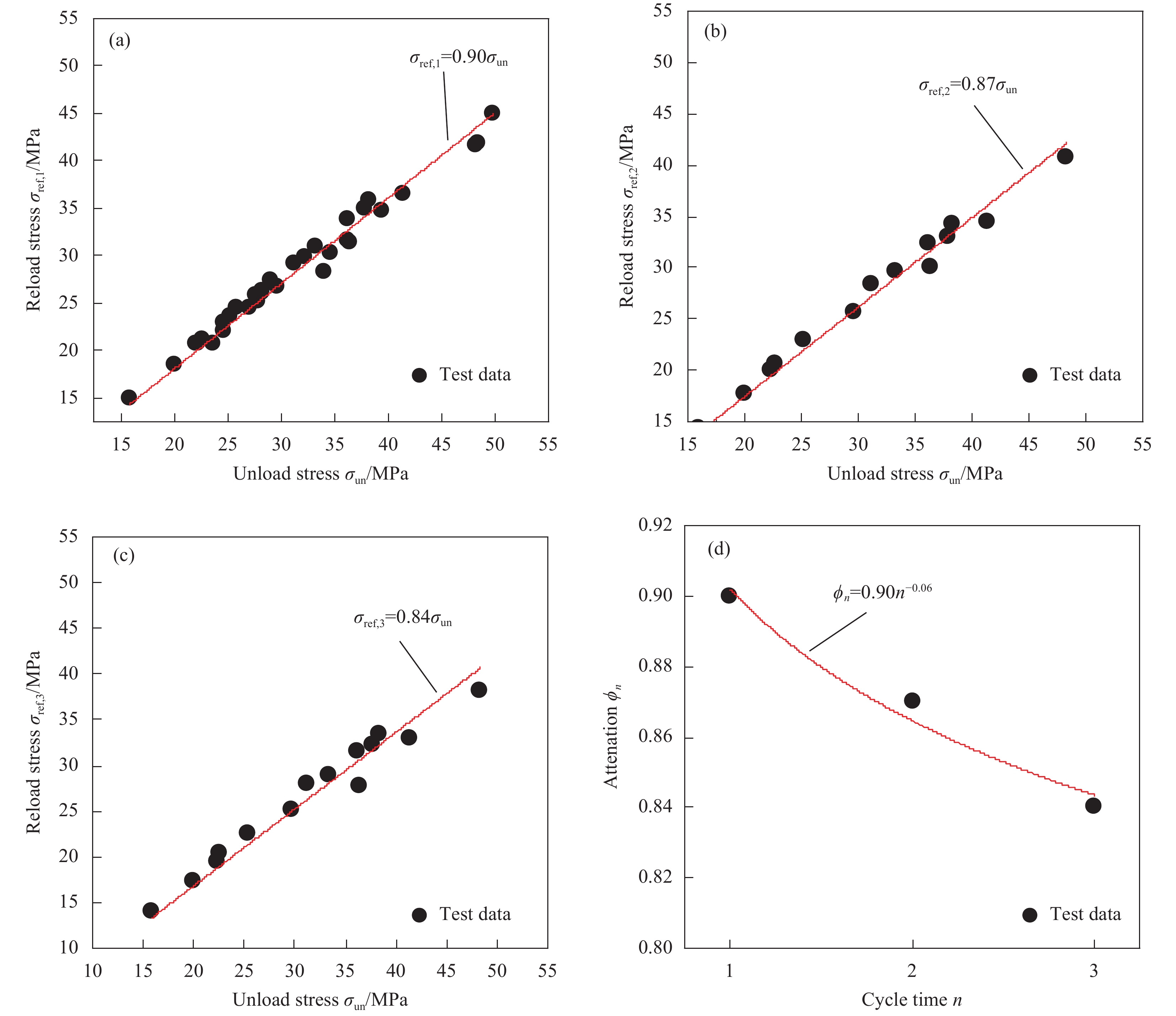
图 13 CFRP-ECC复合约束混凝土圆柱再加载应力与初始卸载点应力关系
Figure 13. Initial unload stress vs reload stress of CFRP-ECC confined cylinders
![]()
图 14 CFRP-ECC复合约束混凝土圆柱残余应变与初始卸载点应变关系
Figure 14. Initial unload strain vs residual plastic strain of CFRP-ECC confined cylinders
![]()
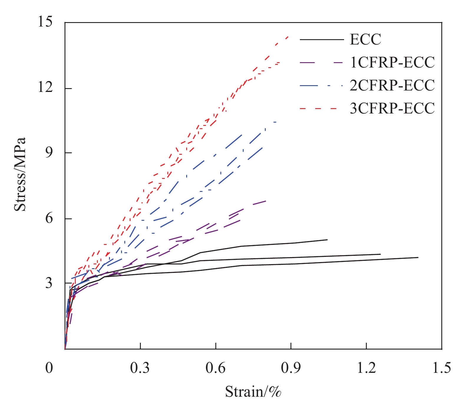
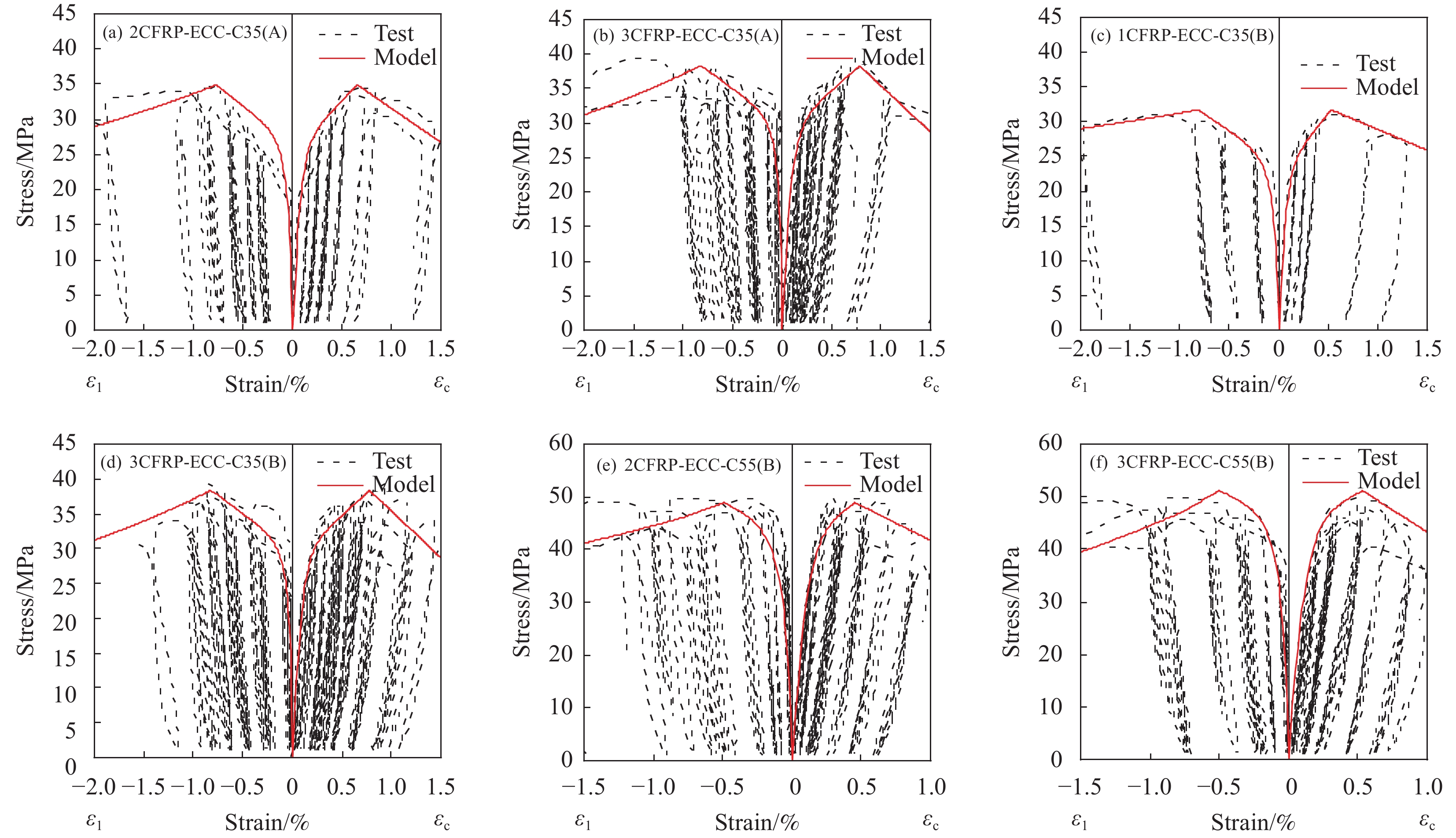
图 15 CFRP-ECC复合约束混凝土圆柱应力-应变关系对比
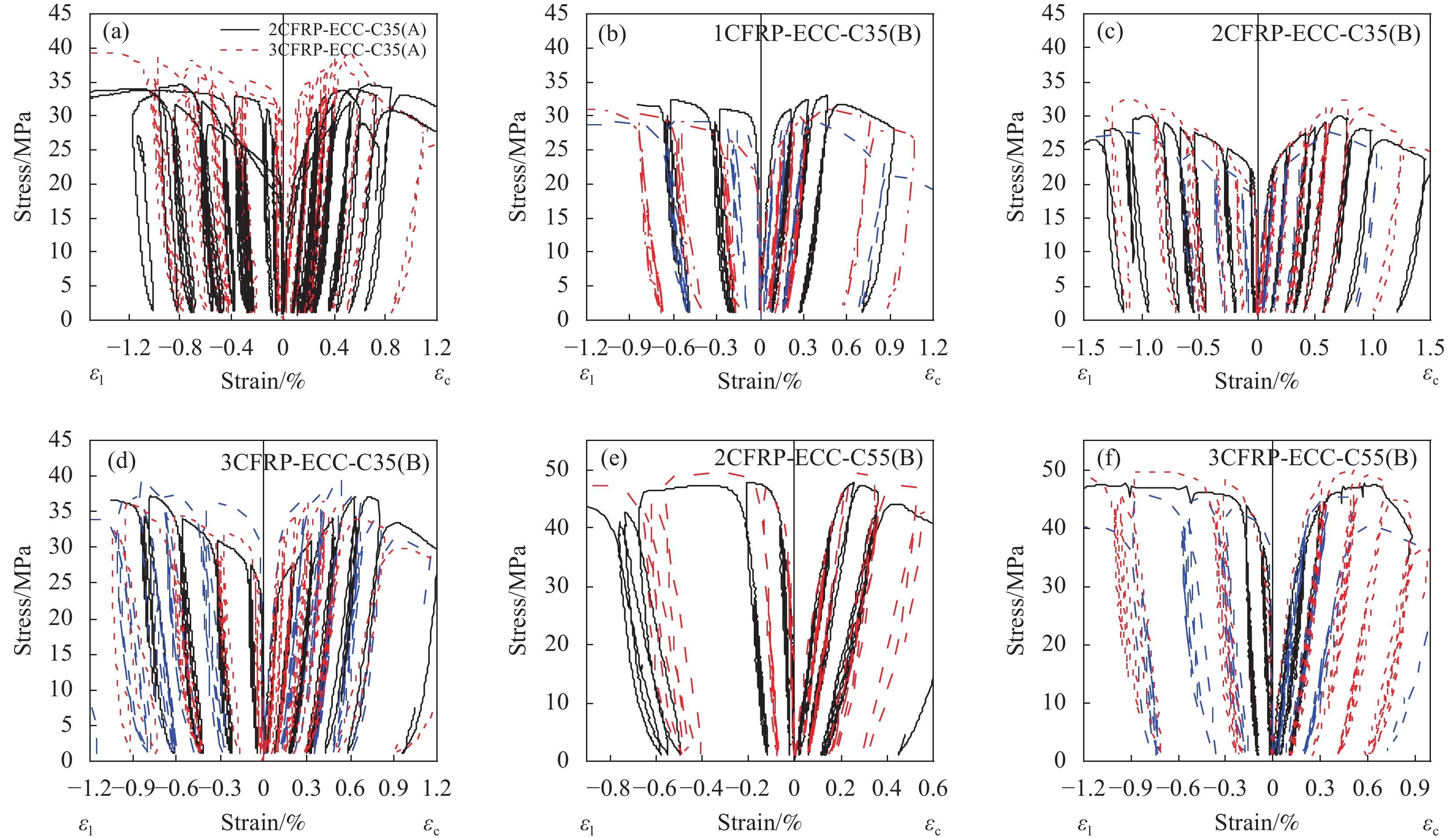
Figure 15. Comparison of stress-strain curves of CFRP-ECC confined cylinders
表 1 工程水泥基复合材料(ECC)配合比
Table 1 Mix proportion of engineered cementitous composites (ECC)
kg/m3 Water Cement Sand Water reducer Fly ash Fiber Silica fume 330 351 317 4.5 1052 26 40  下载: 导出CSV
表 2 试验方案
Table 2 Experimental program
Sample Number in
each groupCFRP
layerThickness of ECC/mm 2CFRP-ECC-C35(A) 3 2 10 3CFRP-ECC-C35(A) 3 3 1CFRP-ECC-C35(B) 3 1 2CFRP-ECC-C35(B) 3 2 3CFRP-ECC-C35(B) 3 3 1CFRP-ECC-C55(B) 3 1 2CFRP-ECC-C55(B) 3 2 3CFRP-ECC-C55(B) 3 3 Notes:For the sample, the first number represents the layer of CFRP textile; CFRP—Carbon fiber reinforced polymer; CFRP-ECC—Strengthening CFRP-ECC composite layer; C35, C55—Strength grade of core concrete; A, B—Loading scheme.
下载: 导出CSV
表 3 素混凝土强度
Table 3 Compressive strength of plain concrete
ID ε′co/% f′co/MPa Average 150 mm cube strength ε′co/% f′co/MPa C35 0.35 25.75 0.32 28.74 36.38 0.28 31.44 0.32 29.03 C55 0.24 48.41 0.24 46.67 59.08 0.28 44.61 0.21 46.99 Notes:ε′co, f′co—Peak strain and stress of plain concrete; Conversion ratio between cylinder and cube is 0.79[43].
下载: 导出CSV
表 4 CFRP-ECC复合约束混凝土圆柱试验数据
Table 4 Test results of CFRP-ECC confined columns
Sample εl/% εcc/% f′cc/MPa Average εcc/ε′co f′cc/f′co εl
/%εcc/% f′cc/MPa 1CFRP-ECC-C35(B)-1 1.06 0.70 33.1 1.07 0.56 31.1 1.77 1.08 1CFRP-ECC-C35(B)-2 1.01 0.39 29.1 1CFRP-ECC-C35(B)-3 1.13 0.60 31.0 2CFRP-ECC-C35(B)-1 0.96 0.71 30.1 1.06 0.67 31.2 2.12 1.09 2CFRP-ECC-C35(B)-2 1.16 0.63 32.3 3CFRP-ECC-C35(B)-1 0.78 0.73 37.2 0.86 0.76 37.7 2.40 1.31 3CFRP-ECC-C35(B)-2 0.95 0.60 36.4 3CFRP-ECC-C35(B)-3 0.85 0.95 39.5 2CFRP-ECC-C55(B)-1 – 0.25 47.8 0.97 0.46 49.1 1.89 1.05 2CFRP-ECC-C55(B)-2 1.15 0.67 49.8 2CFRP-ECC-C55(B)-3 0.78 0.46 49.6 3CFRP-ECC-C55(B)-1 0.88 0.51 47.3 0.88 0.51 47.5 2.10 1.02 3CFRP-ECC-C55(B)-2 – 0.29 45.4 3CFRP-ECC-C55(B)-3 0.88 0.51 49.8 2CFRP-ECC-C35(A)-1 0.80 0.70 34.6 1.01 0.58 34.1 1.83 1.19 2CFRP-ECC-C35(A)-2 1.09 0.56 34.1 2CFRP-ECC-C35(A)-3 1.15 0.48 33.8 3CFRP-ECC-C35(A)-1 0.71 0.79 38.1 1.01 0.78 38.7 2.45 1.35 3CFRP-ECC-C35(A)-2 1.30 0.76 39.3 Notes: εcc and f′cc—Ultimate axial strain and ultimate strength of confined cylinders.
下载: 导出CSV
表 5 CFRP-ECC复合约束混凝土圆柱模型和试验结果对比
Table 5 Comparison of model and test results of CFRP-ECC confined cylinders
Sample Test Prediction Prediction/Test εcc
/%f′cc
/MPaεcc
/%f′cc
/MPaεcc f′cc 1CFRP-ECC-C35(B) 0.56 31.06 0.53 31.72 0.94 1.02 2CFRP-ECC-C35(B) 0.67 31.19 0.65 34.84 0.97 1.12 3CFRP-ECC-C35(B) 0.76 37.68 0.78 38.33 1.03 1.02 2CFRP-ECC-C55(B) 0.46 49.07 0.45 48.98 0.98 1.00 3CFRP-ECC-C55(B) 0.51 47.50 0.53 51.13 1.04 1.08 2CFRP-ECC-C35(A) 0.58 34.13 0.65 34.84 1.13 1.02 3CFRP-ECC-C35(A) 0.78 38.70 0.78 38.33 1.01 0.99 Mean 1.01 1.04 SD 0.06 0.03 CV 0.055 0.034 Notes: Mean—Average value; SD—Standard deviation; CV—Coefficient of variation.
下载: 导出CSV
-
[1] TAELJSTEN B, BLANKSVAERD T. Mineral-based bonding of carbon FRP to strengthen concrete structures[J]. Jour-nal of Composites for Construction,2007,11(2):120-128. DOI: 10.1061/(ASCE)1090-0268(2007)11:2(120)
[2] YU K Q, YU J T, DAI J G, et al. Development of ultra-high performance engineered cementitious composites using polyethylene (PE) fibers[J]. Construction Building Materials,2018,158:217-227. DOI: 10.1016/j.conbuildmat.2017.10.040
[3] POURFALAH S. Behaviour of engineered cementitious composites and hybrid engineered cementitious compo-sites at high temperatures[J]. Construction Building Materials,2018,158(15):921-937.
[4] ZHOU Y W, XI B, YU K Q, et al. Mechanical properties of hybrid ultra-high performance engineered cementitous composites incorporating steel and polyethylene fibers[J]. Materials (Basel),2018,11(8):1448. DOI: 10.3390/ma11081448
[5] ZHOU Y, ZHENG Y, SUI L, et al. Behavior and modeling of FRP-confined ultra-lightweight cement composites under monotonic axial compression[J]. Composites Part B: Engineering,2019,162:289-302. DOI: 10.1016/j.compositesb.2018.10.087
[6] 徐世烺, 蔡新华. 超高韧性水泥基复合材料碳化与渗透性能试验研究[J]. 复合材料学报, 2010, 27(3):177-183. XU Shilang, CAI Xinhua. Experimental studies on permeability and carbonation properties of ultra high toughness cementitious composites[J]. Acta Materiae Compositae Sinica,2010,27(3):177-183(in Chinese).
[7] MA H, ZHANG Z G. Paving an engineered cementitious composite (ECC) overlay on concrete airfield pavement for reflective cracking resistance[J]. Construction and Building Materials,2020,252:119048. DOI: 10.1016/j.conbuildmat.2020.119048
[8] LIU Y M, ZHANG Q H, BAO Y, et al. Static and fatigue push-out tests of short headed shear studs embedded in engi-neered cementitious composites (ECC)[J]. Engineering Structures,2019,182:29-38. DOI: 10.1016/j.engstruct.2018.12.068
[9] LIU H Z, ZHANG Q, LI V, et al. Durability study on engi-neered cementitious composites (ECC) under sulfate and chloride environment[J]. Construction and Building Materials,2017,133:171-181. DOI: 10.1016/j.conbuildmat.2016.12.074
[10] QIU J S, YANG E H. Micromechanics-based investigation of fatigue deterioration of engineered cementitious compo-site (ECC)[J]. Cement and Concrete Research,2017,95:65-74. DOI: 10.1016/j.cemconres.2017.02.029
[11] SINGH M, SAINI B, CHALAK H D. Performance and composition analysis of engineered cementitious composite (ECC)—A review[J]. Journal of Building Engineering,2019,26:100851. DOI: 10.1016/j.jobe.2019.100851
[12] ZHANG D, YU J, WU H, et al. Discontinuous microfibers as intrinsic reinforcement for ductile engineered cementitious composites (ECC)[J]. Composites Part B:Engineering,2020,184:107741. DOI: 10.1016/j.compositesb.2020.107741
[13] 刘少龙. 级配复合水泥基 ECC 的设计制备及其微观力学与拉伸行为的研究[D]. 广州: 华南理工大学, 2020. LIU Shaolong. On the design and preparation, microstructure and tensile behaviors of gap-graded cement-based engineered cementitious composite[D]. Guangzhou: South China University of Technology, 2020(in Chinese).
[14] 徐世烺, 刘问. 超高韧性水泥基复合材料疲劳损伤模型试验[J]. 中国公路学报, 2011, 24(6): 1-8. XU Shilang, LIU Wen. Fatigue damage model test of ultra-high toughness cmentitious composites[J]. China Journal of Highway and Transport, 2011, 24(6): 1-8(in Chinese).
[15] CHEN Y, YAO J, LU Z, et al. Experimental study on the shrinkage reduction of high strength strain-hardening cementitious composites[J]. Cement and Concrete Composites,2019,104:103416. DOI: 10.1016/j.cemconcomp.2019.103416
[16] DING Y, YU J T, YU K Q, et al. Basic mechanical properties of ultra-high ductility cementitious composites: From 40 MPa to 120 MPa[J]. Composite Structures,2018,185:634-645. DOI: 10.1016/j.compstruct.2017.11.034
[17] DING Y, YU K Q, YU J T, et al. Structural behaviors of ultra-high performance engineered cementitious composites (UHP-ECC) beams subjected to bending-experimental study[J]. Construction and Building Materials,2018,177:102-115. DOI: 10.1016/j.conbuildmat.2018.05.122
[18] GUO M H, ZHONG Q L, ZHOU Y W, et al. Influence of flexural loading and chloride exposure on the fatigue behavior of high-performance lightweight engineered cementitious composites[J]. Construction and Building Materials,2020,249:118512. DOI: 10.1016/j.conbuildmat.2020.118512
[19] HUANG B T, LI Q H, XU S L, et al. Fatigue deformation behavior and fiber failure mechanism of ultra-high toughness cementitious composites in compression[J]. Materials & Design,2018,157:457-468.
[20] LI X, ZHOU X, TIAN Y, et al. A modified cyclic constitutive model for engineered cementitious composites[J]. Engi-neering Structures,2019,179:398-411. DOI: 10.1016/j.engstruct.2018.09.030
[21] ZHANG Z G, YANG F, LIU J C, et al. Eco-friendly high strength, high ductility engineered cementitious compo-sites (ECC) with substitution of fly ash by rice husk ash[J]. Cement and Concrete Research,2020:137: 106200.
[22] TIAN J, WU X, ZHENG Y, et al. Investigation of damage behaviors of ECC-to-concrete interface and damage prediction model under salt freeze-thaw cycles[J]. Construction and Building Materials,2019,226:238-249. DOI: 10.1016/j.conbuildmat.2019.07.237
[23] TIAN J, WU X, ZHENG Y, et al. Investigation of interface shear properties and mechanical model between ECC and concrete[J]. Construction and Building Materials,2019,223:12-27. DOI: 10.1016/j.conbuildmat.2019.06.188
[24] BOSHOFF W P, NIEUWOUDT P D. Tensile crack widths of strain hardening cement-based composites[C]//2nd International RILEM Conference on Strain Hardening Cementitious Composites (SHCC2-Rio). Rio de Brazil: RILEM Publications SARL, 2011: 199-206.
[25] 朱忠锋, 王文炜. 玄武岩格栅增强水泥基复合材料单轴拉伸力学性能试验及本构关系模型[J]. 复合材料学报, 2017, 34(10):2367-2374. ZHU Zhongfeng, WANG Wenwei. Experiment on the uniaxial tensile mechanical behavior of basalt grid reinforced engineered cementitious composites and its constitutive model[J]. Acta Materiae Compositae Sinica,2017,34(10):2367-2374(in Chinese).
[26] CHEN C, CAI H Y, LI J J, et al. One-dimensional extended FEM based approach for predicting the tensile behavior of SHCC-FRP composites[J]. Engineering Fracture Mecha-nics,2020,225:106775. DOI: 10.1016/j.engfracmech.2019.106775
[27] 朱忠锋, 王文炜, 郑宇宙, 等. 基于非接触式观测技术的FRP/ECC复合材料反复受拉本构关系模型[J]. 土木工程学报, 2019, 52(10):36-45, 55. ZHU Zhongfeng, WANG Wenwei, ZHENG Yuzhou, et al. The constitutive model of FRP/ECC composite materials under uniaxial cyclic tensile loading based on the digital image correlation technique[J]. China Civil Engineering Journal,2019,52(10):36-45, 55(in Chinese).
[28] ZHU Z F, WANG W W, HARRIES K A, et al. Uniaxial tensile stress-strain behavior of carbon-fiber grid-reinforced engineered cementitious composites[J]. Journal of Composites for Construction, 2018, 22(6): 04018057.
[29] 王新玲, 杨广华, 钱文文, 等. 高强不锈钢绞线网增强工程水泥基复合材料受拉应力-应变关系[J]. 复合材料学报, 2020, 37(12):3220-3228. WANG Xinling, YANG Guanghua, QIAN Wenwen, et al. Tensile stress-strain relationship of engineered cementitious composites reinforced by high-strength stainless steel wire mesh[J]. Acta Materiae Compositae Sinica,2020,37(12):3220-3228(in Chinese).
[30] 夏立鹏, 张黎飞, 郑愚. CFRP增强工程水泥基复合材料桥面连接板的结构和性能[J]. 复合材料学报, 2019, 36(4):848-859. XIA Lipeng, ZHANG Lifei, ZHENG Yu. Structural perfor-mance of CFRP reinforced ECC link slabs in jointless bridge decks[J]. Acta Materiae Compositae Sinica,2019,36(4):848-859(in Chinese).
[31] 朱忠锋, 王文炜. FRP编织网/ECC复合加固钢筋混凝土圆柱力学性能的试验[J]. 东南大学学报(自然科学版), 2016, 46(5):1082-1087. ZHU Zhongfeng, WANG Wenwei. Experimental study on mechanical behaviour of circular reinforced concrete columns strengthened with FRP textile and ECC[J]. Journal of Southeast University (Natural Science Edition),2016,46(5):1082-1087(in Chinese).
[32] YUAN F, CHEN M C, PAN J L. Experimental study on seismic behaviours of hybrid FRP-steel-reinforced ECC-concrete composite columns[J]. Composites Part B: Engineering,2019,176:107272.
[33] ZHU Z F, WANG W W, HUI Y X, et al. Mechanical behavior of concrete columns confined with CFRP grid-reinforced engineered cementitious composites[J]. Journal of Composites for Construction, 2022, 26(1): 4021060.
[34] 江佳斐, 隋凯. 纤维网格增强超高韧性水泥复合材料加固混凝土圆柱受压性能试验[J]. 复合材料学报, 2019, 36(8):1957-1967. JIANG Jiafei, SUI Kai. Experimental study of compression performance of concrete cylinder strengthened by extile reinforced engineering cement composites[J]. Acta Materiae Compositae Sinica,2019,36(8):1957-1967(in Chinese).
[35] HUANG B T, LI Q H, XU S L, et al. Development of reinforced ultra-high toughness cementitious composite permanent formwork: Experimental study and digital image correlation analysis[J]. Composite Structures,2017,180:892-903. DOI: 10.1016/j.compstruct.2017.08.016
[36] ZHENG Y Z, WANG W W, BRIGHAM J C. Flexural behaviour of reinforced concrete beams strengthened with a composite reinforcement layer: BFRP grid and ECC[J]. Construction Building Materials,2016,115(15):424-437.
[37] ZHENG Y Z, WANG W W, MOSALAM K M, et al. Mechani-cal behavior of ultra-high toughness cementitious compo-site strengthened with fiber reinforced polymer grid[J]. Composite Structures,2018,184:1-10. DOI: 10.1016/j.compstruct.2017.09.073
[38] HU B, ZHOU Y W, XING F, et al. Experimental and theoretical investigation on the hybrid CFRP-ECC flexural strengthening of RC beams with corroded longitudinal reinforcement[J]. Engineering Structures,2019,200:109717. DOI: 10.1016/j.engstruct.2019.109717
[39] QIN F J, ZHANG Z G, YIN Z W, et al. Use of high strength, high ductility engineered cementitious composites (ECC) to enhance the flexural performance of reinforced concrete beams[J]. Journal of Building Engineering,2020,32:101746. DOI: 10.1016/j.jobe.2020.101746
[40] YUAN F, CHEN M C, PAN J L. Flexural strengthening of reinforced concrete beams with high-strength steel wire and engineered cementitious composites[J]. Construction and Building Materials,2020,254:119284. DOI: 10.1016/j.conbuildmat.2020.119284
[41] LIN Y W, WOTHERSPOON L, SCOTT A, et al. In-plane strengthening of clay brick unreinforced masonry wallettes using ECC shotcrete[J]. Engineering Structures,2014,66(5):57-65.
[42] DENG M K, DONG Z F, MA P. Cyclic loading tests of flexural-failure dominant URM walls strengthened with engineered cementitious composite[J]. Engineering Structures,2019,194:173-182. DOI: 10.1016/j.engstruct.2019.05.073
[43] 中华人民共和国住房和城乡建设部. 普通混凝土力学性能试验方法标准: GB/T 50081—2002[S]. 北京: 中国建筑工业出版社, 2003. Ministry of Housing and Urban-Rural Development of the People's Republic of China. Standard for test method of mechanical properties on ordinary concrete: GB/T 50081—2002[S]. Beijing: China Architecture & Publishing Press, 2003(in Chinese).
[44] ZHOU Y W, WU Y F. General model for constitutive relationships of concrete and its composite structures[J]. Composite Structures,2012,94(2):580-592. DOI: 10.1016/j.compstruct.2011.08.022
[45] ZHOU Y, LIU X, XING F, et al. Axial compressive behavior of FRP-confined lightweight aggregate concrete: An experimental study and stress-strain relation model[J]. Construction and Building Materials,2016,119:1-15. DOI: 10.1016/j.conbuildmat.2016.02.180
[46] LI P D, WU Y F, ZHOU Y W, et al. Stress-strain model for FRP-confined concrete subject to arbitrary load path[J]. Composites Part B: Engineering,2019,163:9-25. DOI: 10.1016/j.compositesb.2018.11.002
[47] LI P D, SUI L L, XING F, et al. Stress-strain relation of FRP-confined predamaged concrete prisms with square sections of different corner radii subjected to monotonic axial compression[J]. Journal of Composites for Construction,2019,23(2):04019001. DOI: 10.1061/(ASCE)CC.1943-5614.0000921
[48] LAM L, TENG J. Design-oriented stress-strain model for FRP-confined concrete in rectangular columns[J]. Journal of Reinforced Plastics Composites in Construction,2003,22(13):1149-1186. DOI: 10.1177/0731684403035429
[49] WU Y F, YUN Y C, WEI Y Y, et al. Effect of predamage on the stress-strain relationship of confined concrete under monotonic loading[J]. Journal of Structural Engineering,2014,140(12):04014093. DOI: 10.1061/(ASCE)ST.1943-541X.0001015
[50] TENG J G, HUANG Y L, LAM L, et al. Theoretical model for fiber-reinforced polymer-confined concrete[J]. Journal of Composites for Construction, 2007, 11(2): 201-210.
[51] DAI J, BAI Y, TENG J G. Behavior and modeling of concrete confined with FRP composites of large deformability[J]. Journal of Composites for Construction,2011,15(6):963-973. DOI: 10.1061/(ASCE)CC.1943-5614.0000230
[52] SHAO Y, ZHU Z, MIRMIRAN A. Cyclic modeling of FRP-confined concrete with improved ductility[J]. Cement and Concrete Composites,2006,28(10):959-968. DOI: 10.1016/j.cemconcomp.2006.07.009
-
期刊类型引用(1)
1. 张飞宇,丁琪,武振强,李果,赵云松,姚建省,夏敏,姜乃生. 精密铸造用硅溶胶黏结剂研究现状. 特种铸造及有色合金. 2025(01): 6-14 .  百度学术
百度学术
其他类型引用(3)
-


计量
- 文章访问数: 1197
- HTML全文浏览量: 542
- PDF下载量: 91
- 被引次数: 4
