


Effect factors of stress distribution and failure behavior of threaded connection for carbon materials
-
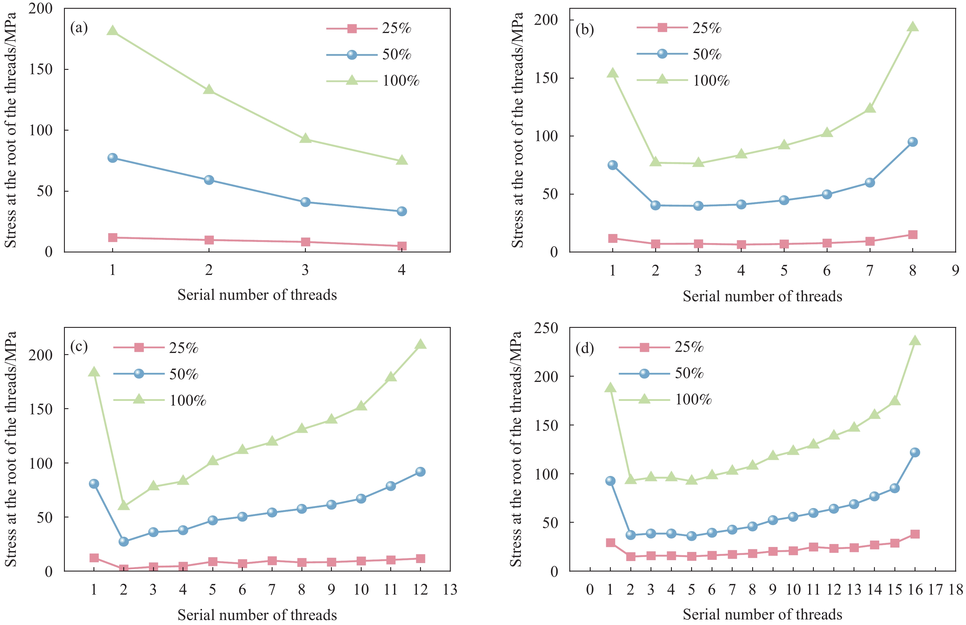
摘要: 了解螺纹连接结构应力分布有助于预测连接件在实际工况下的损伤和失效行为。然而碳材料本身的脆性,以及受载时形变主要发生于内部螺纹的特性,常用的数字图像法(DIC)等应力分析手段并不适用。本文采用有限元仿真方法,对受载时的均质石墨螺柱-螺母内外连接结构进行研究。研究了弹性阶段,螺距P、螺纹咬合齿数n对结构应力变化的影响,并分析其损伤过程。结果表明:当螺纹咬合齿数值较小时,载荷分布较均匀,螺母的受载荷端面螺纹根部发生轻微应力集中。随着螺纹咬合齿数值的增加,连接部分螺纹根部的应力分布呈U型分布,两端螺纹承担更多应力,同时承载螺纹数量增加,导致螺纹连接强力提高。而螺距对于螺纹连接的整体应力分布影响较小。von Mises应力分布云图表明,螺母两端的应力集中最为严重,且随着载荷增加,内外螺纹根部的应力集中加剧,两端的螺纹区域将最先发生失效。Abstract: Understanding the stress distribution of threaded connection can help to predict the damage and failure behavior of the joints under actual working conditions. However, due to the brittle nature of carbon materials and the fact that deformation under load mainly occurs in the internal threads, commonly used stress analysis methods such as digital image method (DIC) are not applicable. In this paper, a finite element simulation method was used to investigate the internal and external connection structure of a homogeneous graphite stud-nut under load. The effects of pitch P and the number of thread bite teeth n on the stress change of the structure during the elastic phase were investigated, and the damage process was analyzed. The results show that when the value of thread bite teeth is small, the load distribution is more uniform and a slight stress concentration occurs at the root of the thread on the loaded end face of the nut. With the increase of the number of teeth of the thread, the stress distribution at the root of the connecting part shows a U-shaped distribution, and the two ends of the thread bear more stress. At the same time, the number of carrying threads increases, resulting in the increase of the strength of the thread connection. The pitch for threaded connections has little impact on the overall stress distribution. The von Mises stress distribution chart shows that the stress concentration at the ends of the nut is most serious, and with the increase of load, the internal and external screw thread root stress concentration increased, at the ends of the thread area will be the first failure happened.
-
Key words:
- carbon material /
- screw joint structure /
- thread parameter /
- stress distribution /
- damage behavior
-
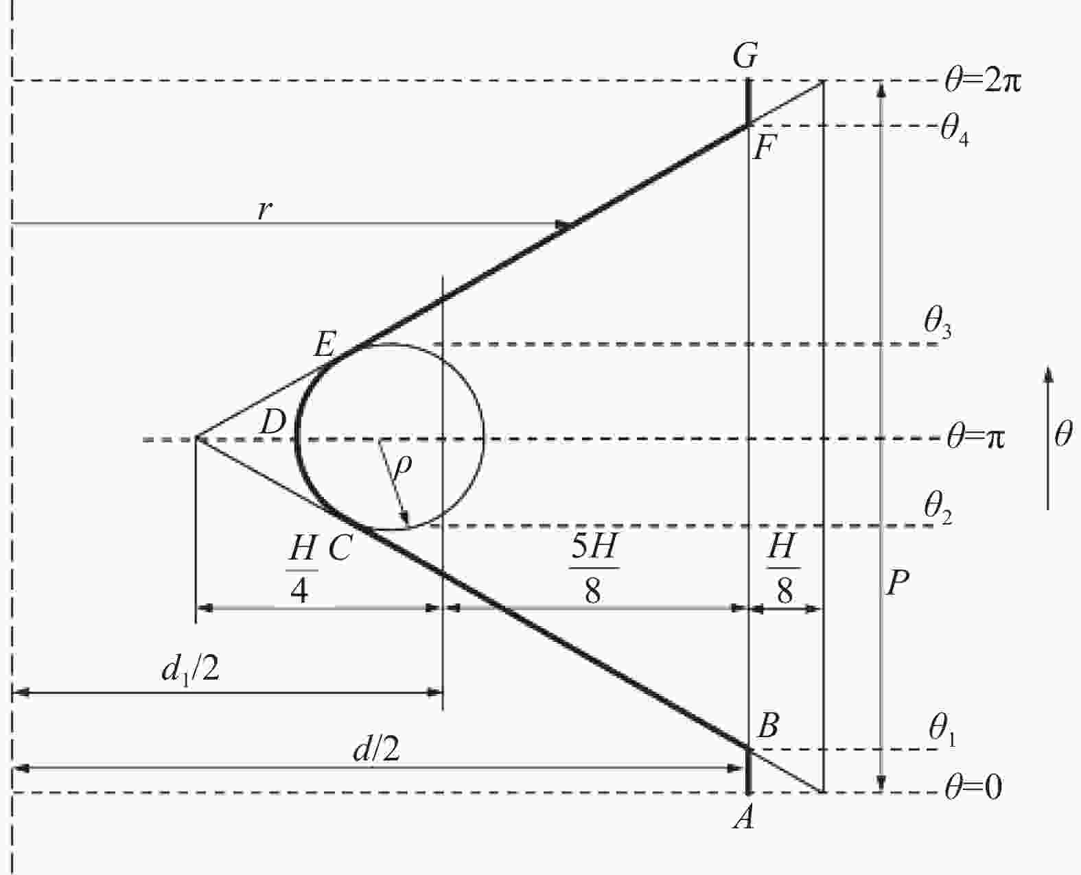
图 1 沿螺柱中心轴线的螺纹截面
Figure 1. Section of the thread along the central axis of the stud
P—Pitch; H—Height of thread; R—Radial coordinate; θ—Circumferential coordinate; d1—Thread path; d—Nominal diameter of the thread; ρ—Radius of the tooth root
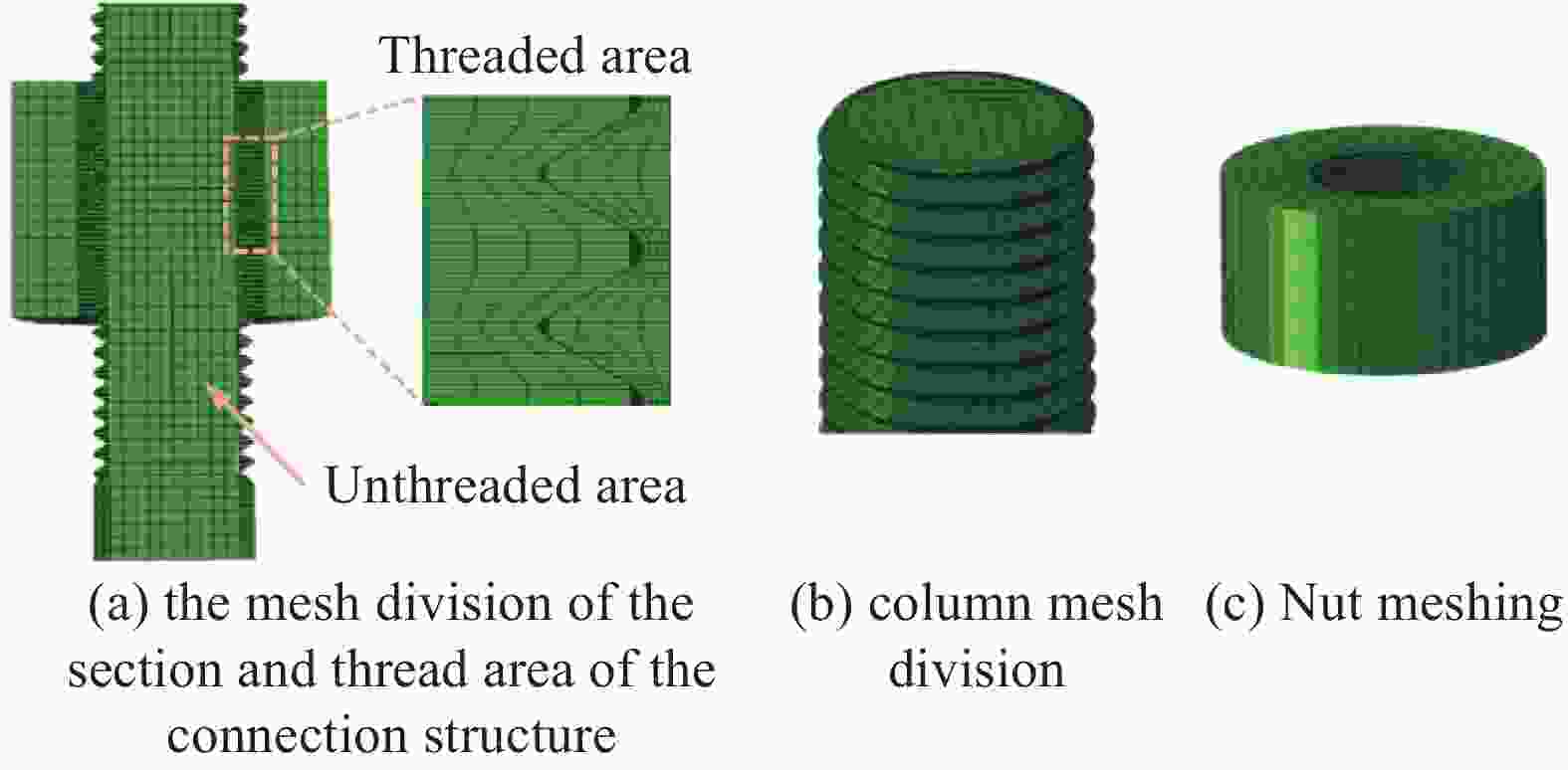
图 3 螺纹连接结构网格模型
Figure 3. Mesh model of threaded connection structure:
(a) the mesh division of the section and thread area of the connection structure; (b) column mesh division; (c) Nut meshing

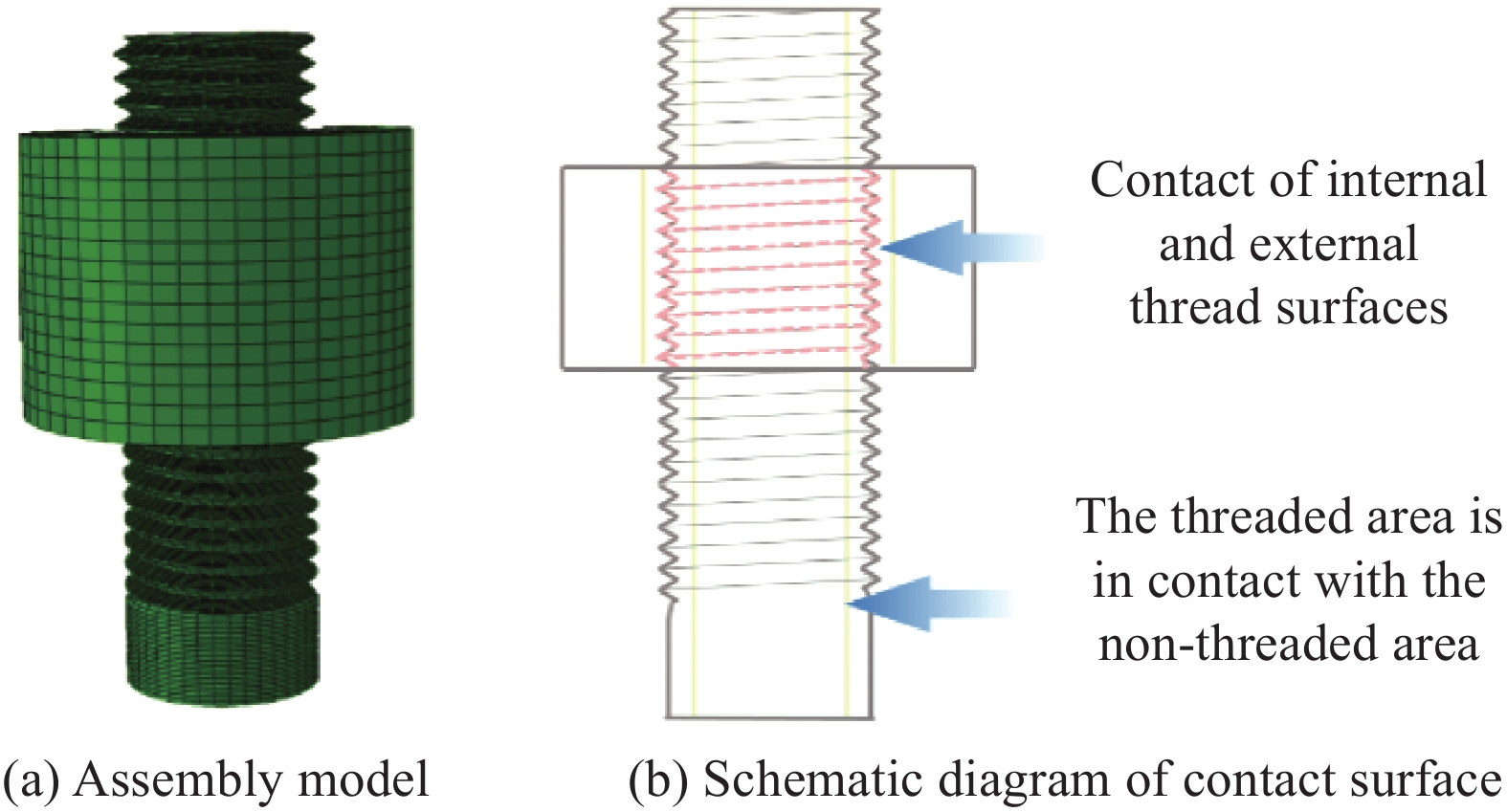
图 4 螺纹连接结构装配模型及接触面示意图
Figure 4. Assembly model and contact surface diagram of threaded connection structure
(a) Assembly model (b) Schematic diagram of contact surface
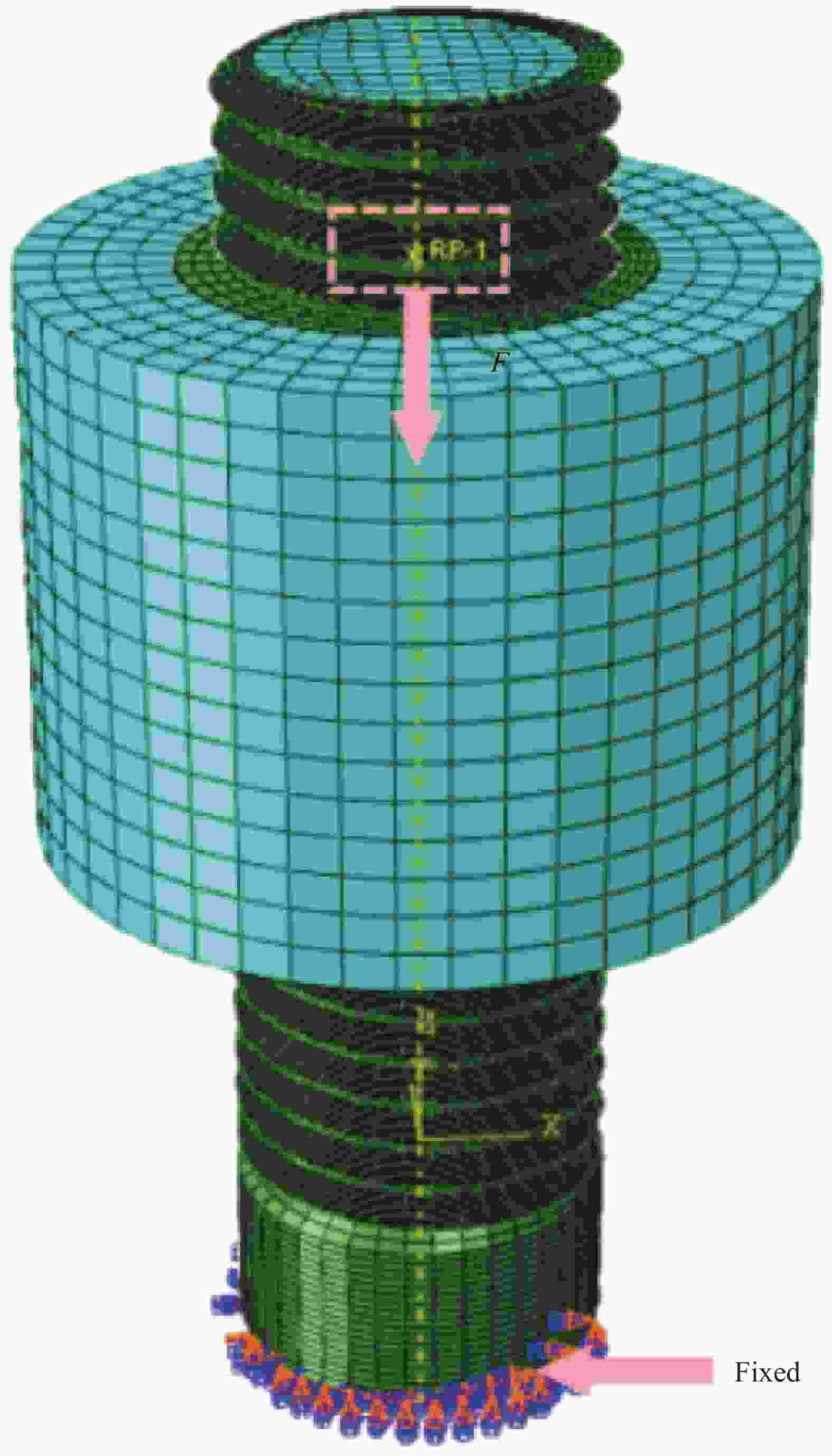
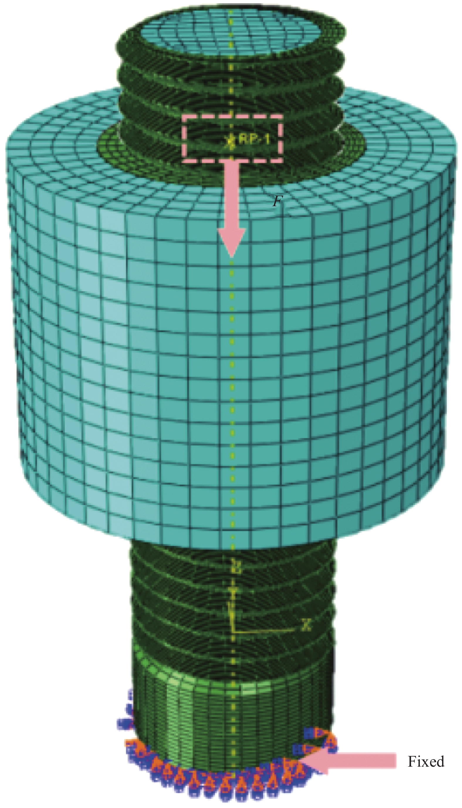
图 5 有限元仿真计算时边界条件示意图
Figure 5. Schematic diagram of boundary conditions in finite element simulation
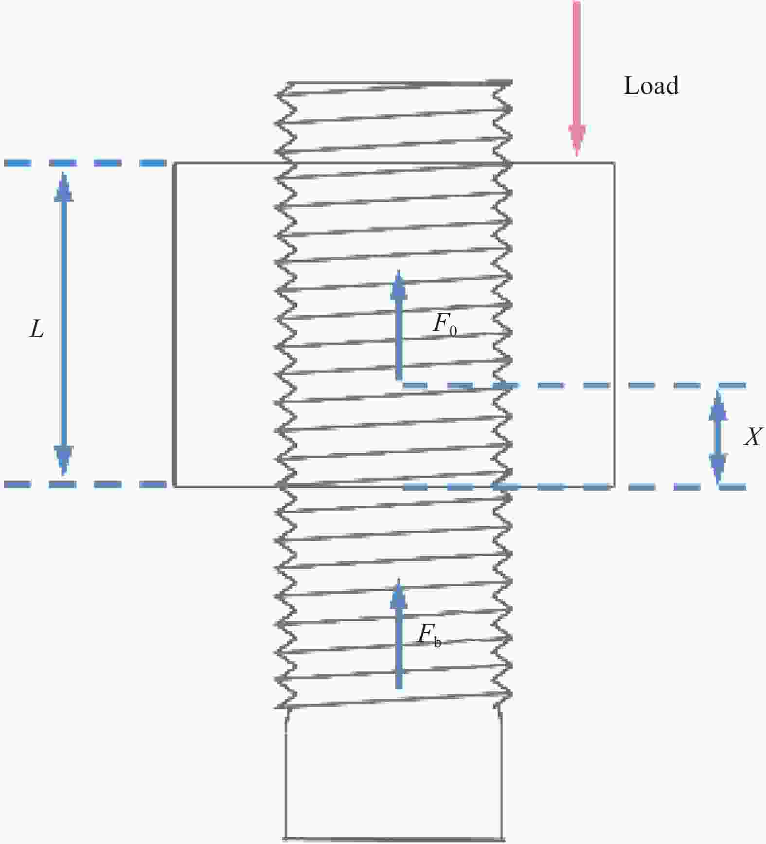
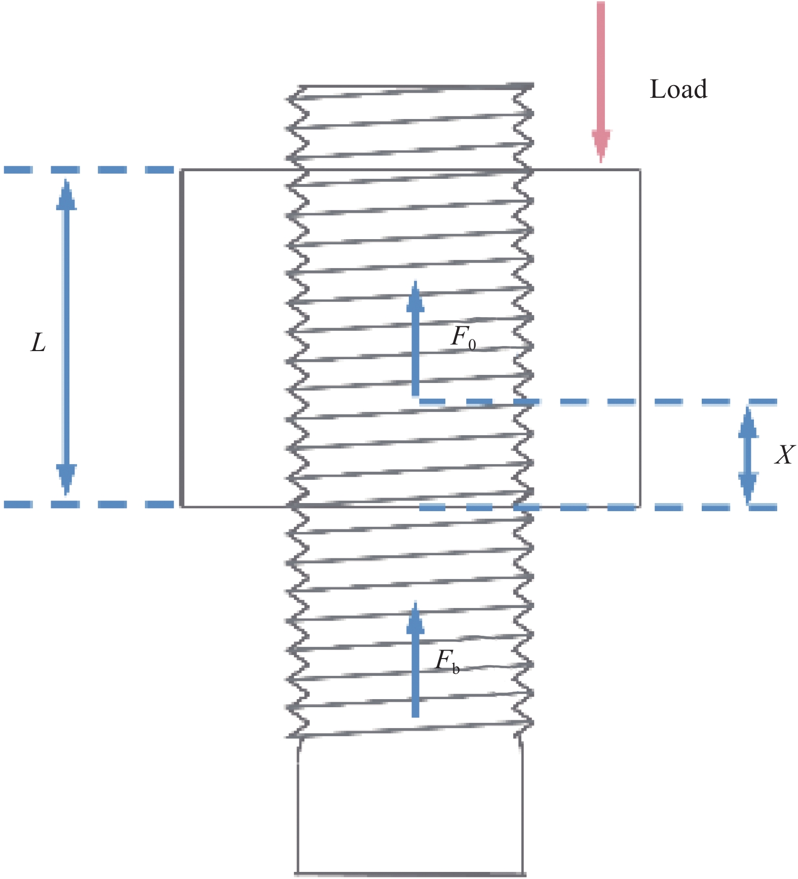
图 6 旋合螺纹连接部分轴向力示意图
Figure 6. Axial force diagram of threaded connection part
L—Threaded screwing length; F0—Axial force on the vertical section of a stud; Fb—Force applied to the stud axial; X—Distance from the bottom of the nut to the X position
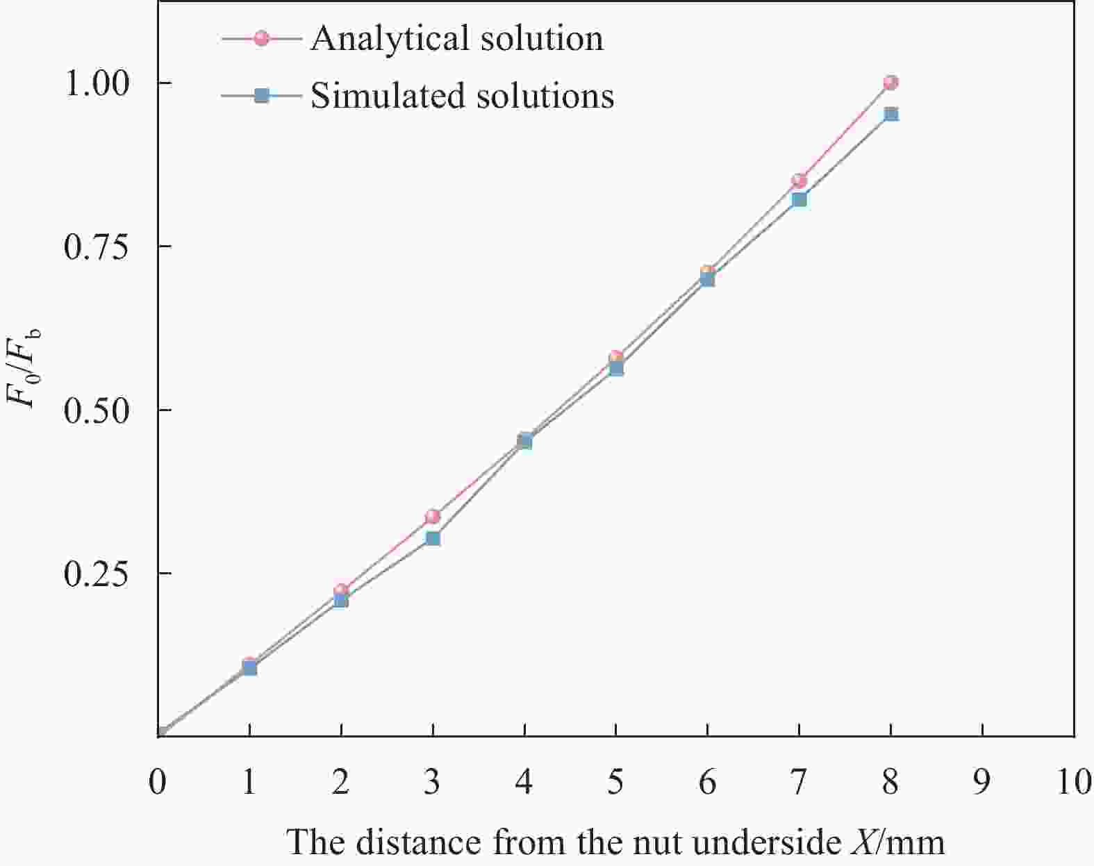
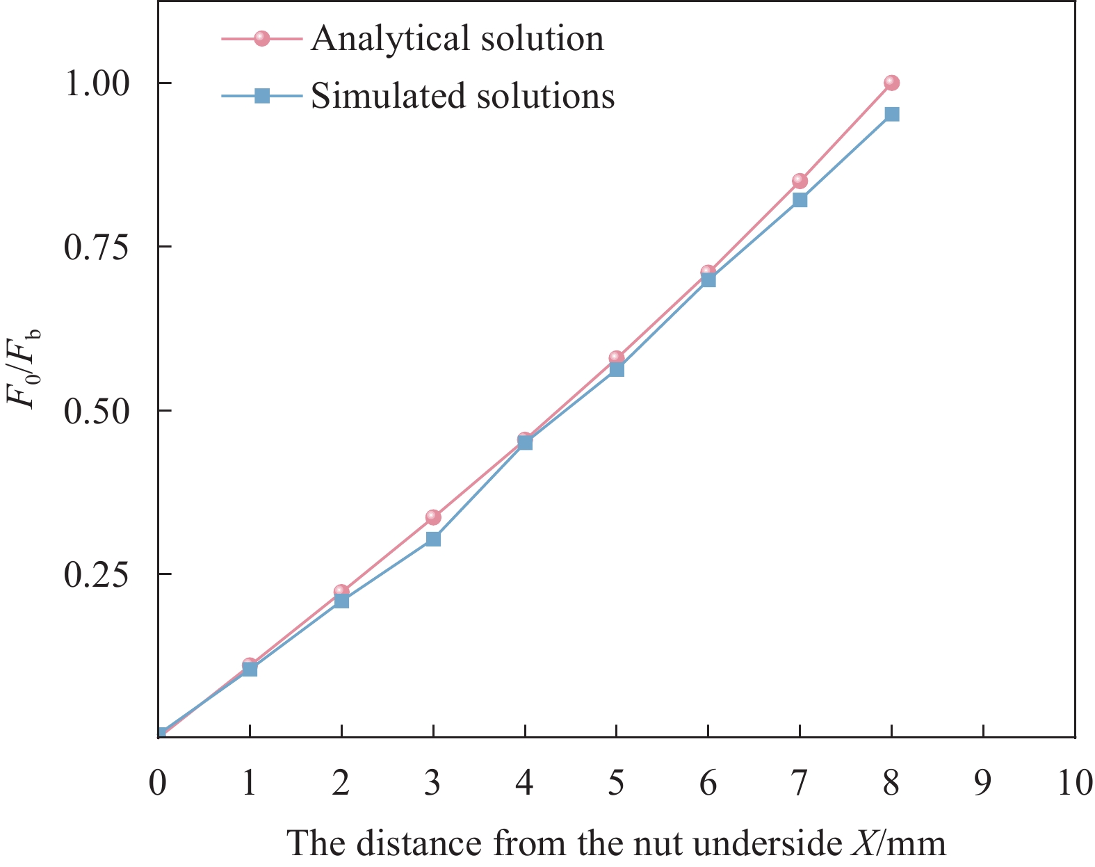
图 7 25%实验载荷下解析解和模拟解对比
Figure 7. Comparison of analytical solution and Simulation solution under 25% experimental load
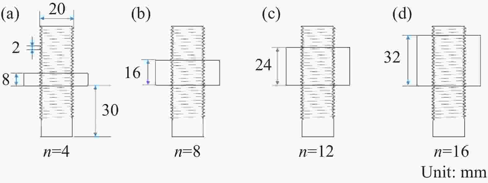
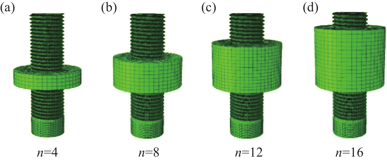
图 8 不同螺纹咬合齿数石墨螺纹连接结构尺寸示意图
Figure 8. Schematic diagram of graphite thread connection structure size with different thread occlusion teeth

图 9 不同螺纹咬合齿数n连接结构模型图
Figure 9. Diagram of connection structure model with different number of teeth
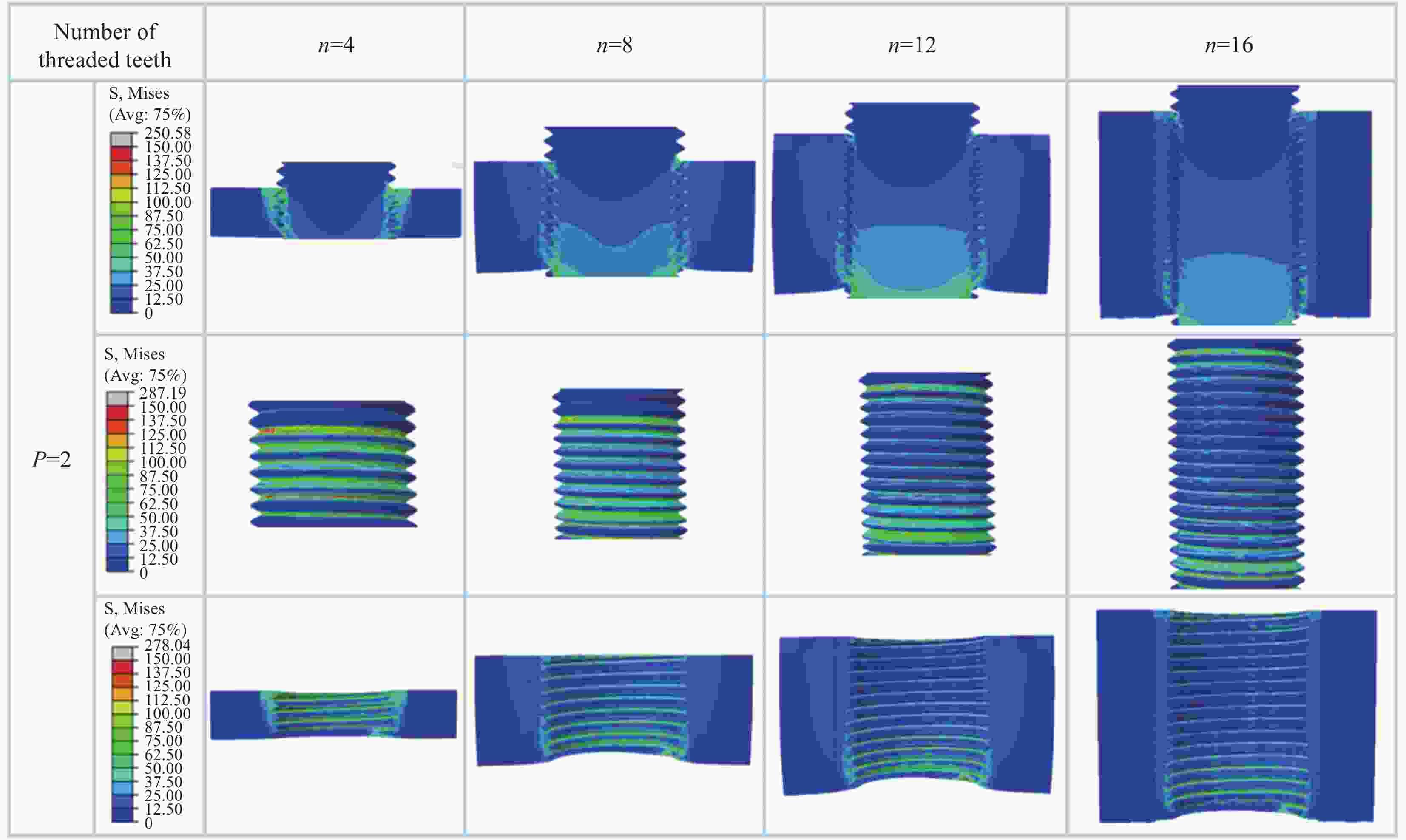
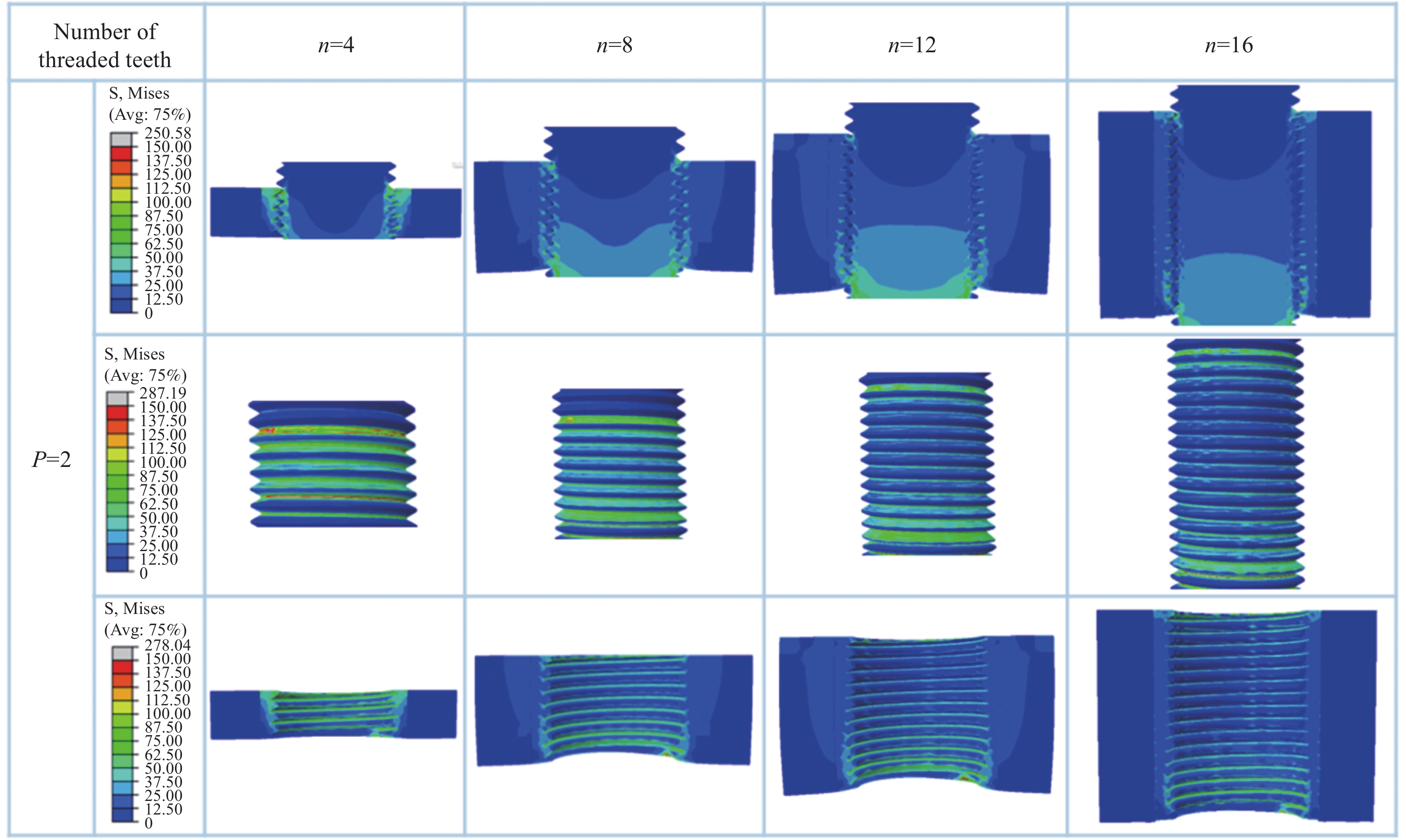
图 11 不同咬合齿数石墨螺纹连接结构应力分布云图
Figure 11. Stress distribution nephogram of graphite thread connection structure with different number of teeth
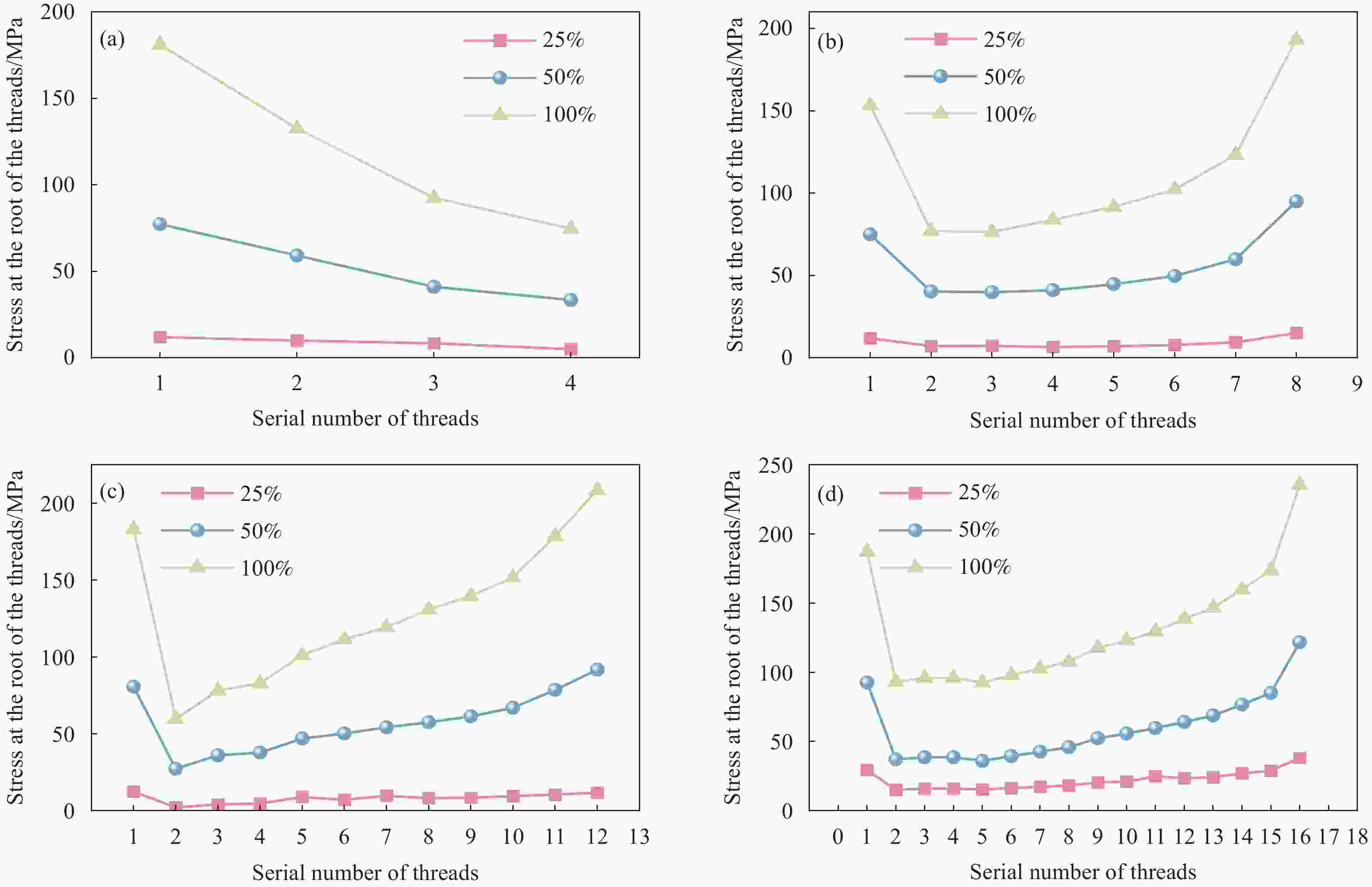
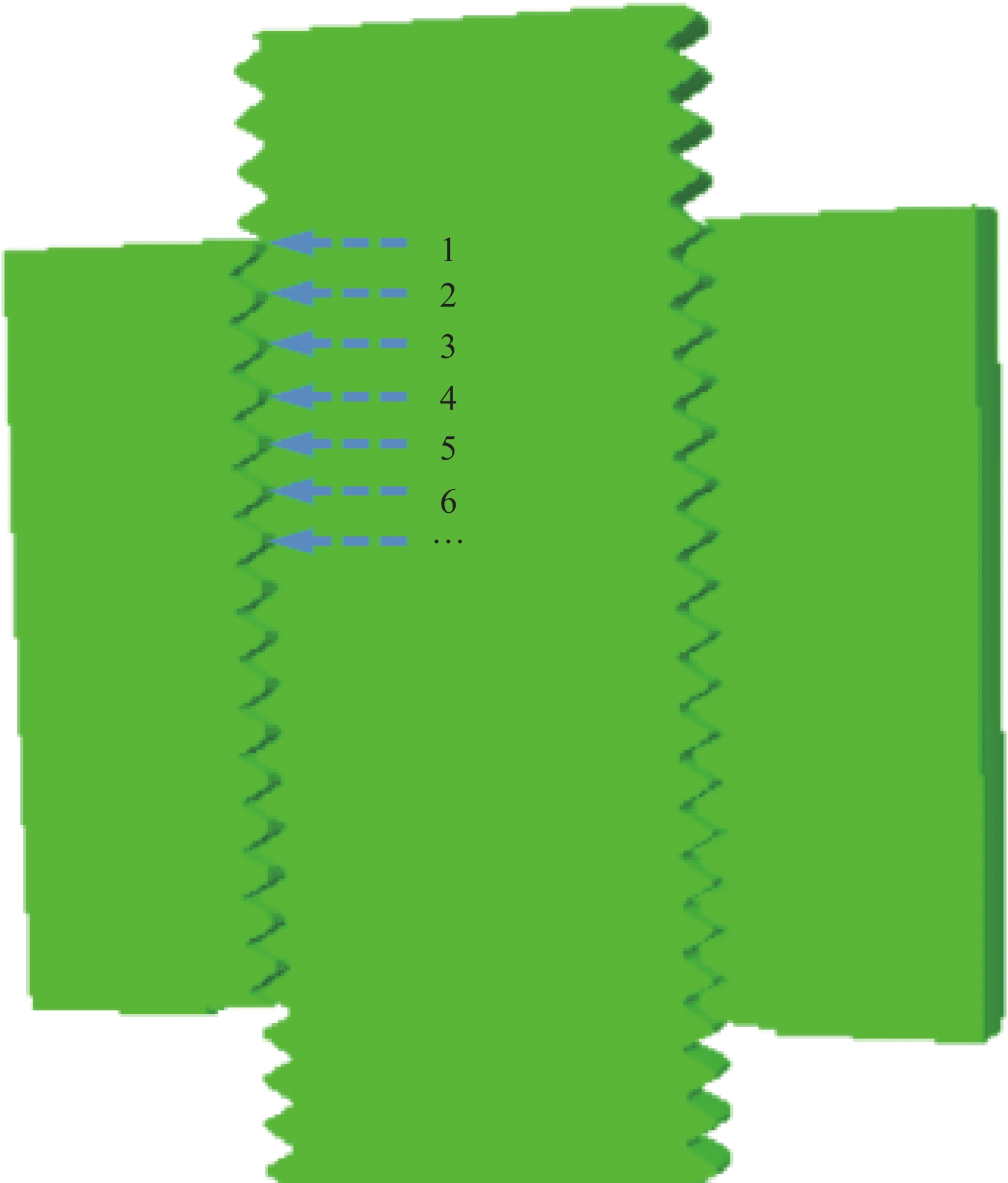
图 12 石墨螺纹根部的应力情况:(a) n=4;(b) n=8;(c) n=12;(d) n=16
Figure 12. TStress of the root of the graphite screw thread: (a) n=4; (b) n=8; (c) n=12; (d) n=16
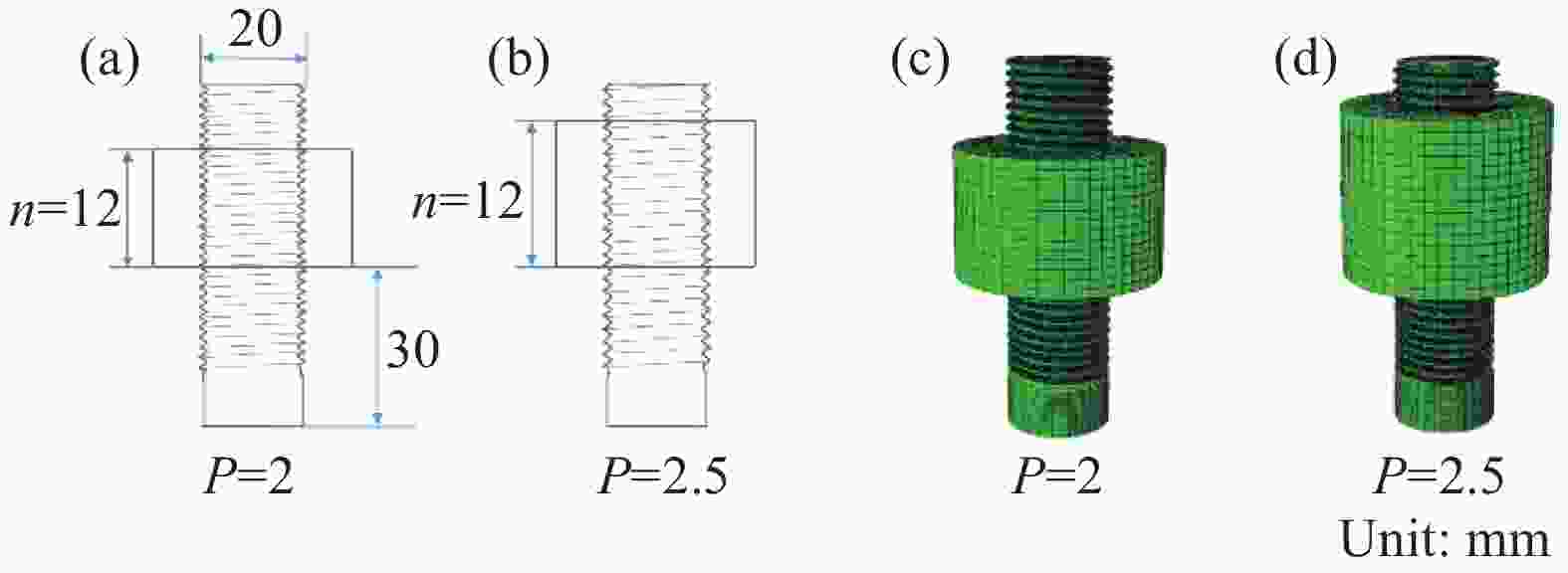
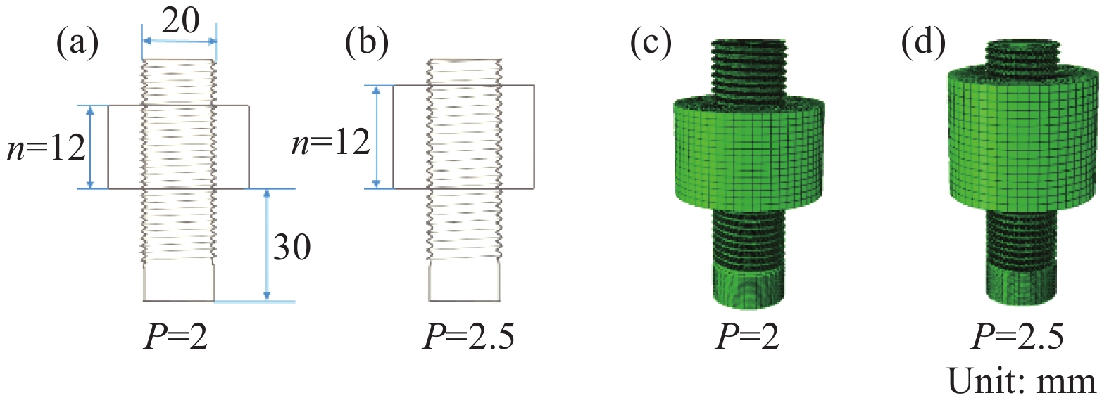
图 13 不同螺距连接结构示意图:(a)、(b)尺寸;(c)、(d)模型
Figure 13. Different pitch connection structure diagram: (a), (b) size; (c), (d) model
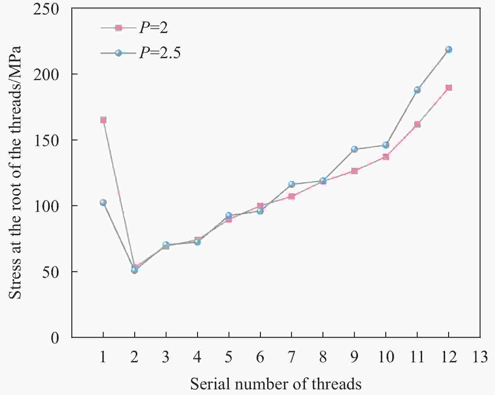
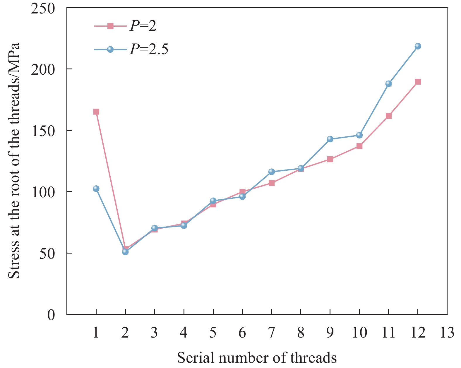
图 14 10 kN载荷下螺纹根部应力分布
Figure 14. Stress distribution of screw thread root under 10 kN load
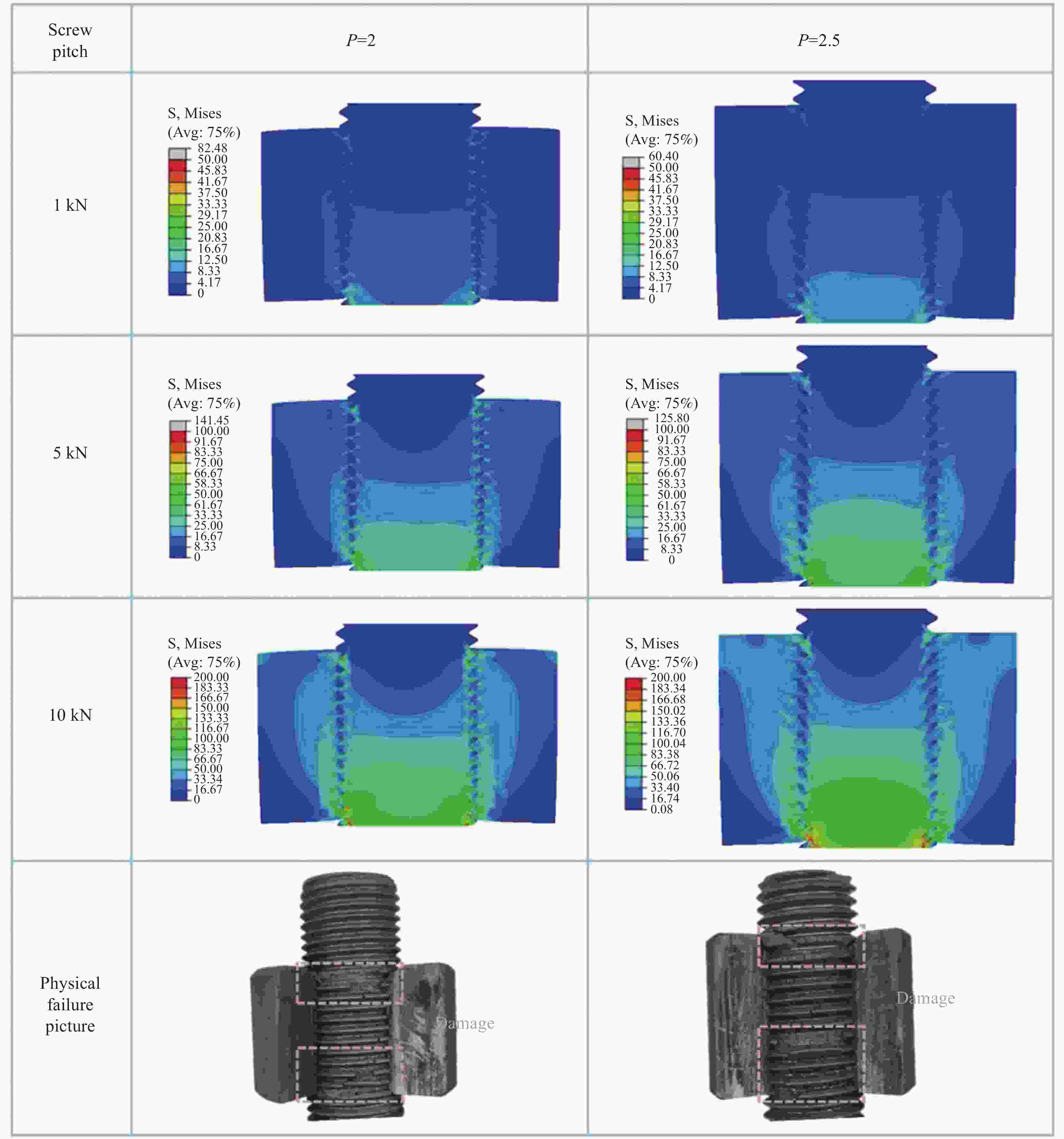
图 15 P=2和P=2.5螺纹连接结构的应力分布云图和实际损伤形貌
Figure 15. Stress distribution chart and the actual damage morphology of P=2 and P=2.5 threaded connection structure
表 1 模型不同部位网格情况
Table 1. Mesh situation of different parts of the model
Mesh Stud Nut Thread area Unthread area Thread area Unthread area Type C3D8 C3D8 C3D8 C3D8 Number of mesh 99200 4512 48000 2880 Number of node 124200 5424 60200 3840  下载: 导出CSV
表 2 材料基本性能参数
Table 2. Basic performance parameters of materials
Material Density ρ /(g·cm−3) Young's modulus E /GPa Poisson's ratio ν Graphite 1.85 10 0.15
下载: 导出CSV
表 3 25%实验载荷下解析解和有限元解差异
Table 3. Difference between analytical solution and finite element solution under 25% experimental load
X Theoretical
solution αSolution
simulation βRate of
deviation/%0 0 0.005 - 1 0.110 0.105 5.27 2 0.222 0.209 5.88 3 0.337 0.303 9.81 4 0.455 0.451 0.97 5 0.579 0.563 2.86 6 0.710 0.699 1.55 7 0.850 0.822 3.33 8 1 0.953 4.74
下载: 导出CSV
表 4 不同咬合齿数石墨螺纹连接结构的模拟工作载荷
Table 4. Simulated working load of graphite threaded connection structure with different number of teeth
n Load of
experiment/kNSimulated
load ratio/%Load of
simulation/kN4 2.74 25
75
1000.69
2.06
2.748 8.12 25
75
1002.03
6.09
8.1212 11.98 25
75
1003.00
6.00
11.9816 13.49 25
75
1003.37
10.12
13.49
下载: 导出CSV
-
[1] FENG W, QIN M M, FENG Y Y. Toward highly thermally conductive all-carbon composites: Structure control[J]. Carbon, 2016, 109: 575-597. doi: 10.1016/j.carbon.2016.08.059 [2] YIN X M, ZHANG X, LIU H M, et al. Novel Structural Design Strategies in Ceramic-Modified C/C Composites[J]. Accounts of Materials Research, 2023, 4(12): 1095-1107. doi: 10.1021/accountsmr.3c00192 [3] 沈杰, 陈红鸟, 陆忠晓, 等. 核工程石墨断裂力学研究进展[J]. 应用力学学报, 2023, 40(6): 1213-1238.SHEN Jie, CHEN Hongniao, LU Zhongxiao, et al. Research progress in fracture mechanics of graphite for nuclear engineering[J]. Chinese journal of applied mechanics, 2023, 40(6): 1213-1238 (in Chinese). [4] YU M M, LI H L, XUE K, et al. Effect of microstructure evaluation during the PIP process on macroscopic properties of C/C composites[J]. Composite Structures, 2023, 308: 116651. doi: 10.1016/j.compstruct.2022.116651 [5] ZHANG G F, ZHANG Y, BAO J D, et al. A novel active braze composition design route for C/C composite using Fe as active element[J]. Carbon, 2021, 181: 177-192. doi: 10.1016/j.carbon.2021.05.012 [6] CHENG Z, FANG H. C, ZHU J. M, et al. Effect of carbon type and morphology on the microstructure and properties of carbon/copper composites[J]. Wear, 2020, 460-461: 203473. doi: 10.1016/j.wear.2020.203473 [7] WANG M, ZENG C, GUO Y, et al. In situ growth of SiC nanowires toughened preceramic resin-based adhesive for connecting Cf/C composites in extreme environments[J]. Ceramics International, 2020, 46(16): 24860-24872. doi: 10.1016/j.ceramint.2020.06.270 [8] BELARDI V, FANELLI P, VIVIO F. FE analysis of single-bolt composite bolted joint by means of a simplified modeling technique[J]. Procedia Structural Integrity, 2019, 24: 888-897. doi: 10.1016/j.prostr.2020.02.078 [9] BELARDI V, FANELLI P, VIVIO F. A novel composite bolted joint element: application to a single-bolted joint[J]. Procedia Structural Integrity, 2018, 12: 281-295. doi: 10.1016/j.prostr.2018.11.087 [10] YUE X, AN L, YE X, et al. Effect of Gap and Shims on the Strain and Stress State of the Composite-Aluminum Hybrid Bolted Structure[J]. International Journal of Aerospace Engineering, 2020, 5: 1-19. [11] 龙旦风, 黄成海, 徐卫国, 等. 基于简化模型仿真的内螺纹应力分析方法研究[J]. 计算力学学报, 2016, 33(6): 939-945.LONG Danfeng, HUANG Chenghai, XU WeiGuo, et al. Research on stress analyzing approach of internal threads based on simplified-model simulation[J]. Chinese Journal of Computational Mechanics, 2016, 33(6): 939-945 (in Chinese). [12] HOLLOCH J. Neue Modellklasse 3b: Modellierung einer Schraube als Solid mit einem vereinfachten Ersatzgewinde[J]. VDI Berichte, 2022, 2403: 167-178. [13] TIM W, SEBASTIAN H, ULI B. Neue A simplified and semi-analytical bolted joint model for crash and impact simulations of composite structures[J]. Composite Structures, 2020, 233: 111628. doi: 10.1016/j.compstruct.2019.111628 [14] DENG W, DAN L P, JIA D W, et al. Steel–aluminum screw–thread pair tightening mechanism and fastening axial force conversion efficiency[J]. Results in Engineering, 2024, 22: 102049. doi: 10.1016/j.rineng.2024.102049 [15] LIN Q Y, ZHAO Y, PAN W, et al. An improved 3D model of composite bolted joints with detailed thread structure and progressive damage analysis of realistic tightening process[J]. Composite Structures, 2023, 315: 117016. doi: 10.1016/j.compstruct.2023.117016 [16] 李佳泽, 朱晓磊, 陆晓峰. 横向振动载荷下有无螺纹配合间隙对连接松脱性能的影响[J]. 化工机械, 2024, 51(2): 242-251.LI Jiaze, ZHU Xiaolei, LU Xiaofeng. Influence of Threaded Joint Fit Clearance on Loosening Performance under Transverse Vibration Load[J]. Chemiacl Engineering & Machinery, 2024, 51(2): 242-251 (in Chinese). [17] JIA D W, CAI C, LI Y P, et al. Research on optimizing the axial force of thread connection of engine connecting rod[J]. Engineering Failure Analysis, 2021, 130: 105771. doi: 10.1016/j.engfailanal.2021.105771 [18] 涂文兵, 何海斌, 王筱鑫, 等. 螺纹深度和螺距对螺纹连接强度影响的有限元分析[J]. 华东交通大学学报, 2017, 34(2): 118-123.TU Wenbing, HE Haibin, WANG Xiaoxin, et al. FEM Analysis of the Effect of Thread Pitch and Depth on Strength of the Threaded Connection[J]. Journal of East China Jiaotong University, 2017, 34(2): 118-123 (in Chinese). [19] LIU F Q, GUAN Z D, BIAN T Y. Damage model for predicting shear strength of carbon/carbon composite fastener based on post-failure behavior[J]. Composite Structures, 2019, 221: 110864. doi: 10.1016/j.compstruct.2019.04.036 [20] ZHANG J T, YANG T, DU Y, et al. Tensile mechanical properties and damage analysis of layered woven GFRP composite bolts[J]. Composites Part B: Engineering, 2024, 271: 111155. doi: 10.1016/j.compositesb.2023.111155 [21] CHEN F, ZHANG J N, WANG C C, et al. Three-dimensional mechanical characteristics analysis of bolted joints and loosening mechanism[J]. Engineering Failure Analysis, 2024, 157: 107894. doi: 10.1016/j.engfailanal.2023.107894 -


 下载:
下载:


 点击查看大图
计量
- 文章访问数: 62
- HTML全文浏览量: 36
- 被引次数: 0
