


Influence of embossed wrinkle and its grinding on the compressive failure behavior of laminates
-
摘要: 评估打磨处理对含外突褶皱结构承载能力的影响,是开展复合材料制造质量评定与制定装配策略的重要依据。本文采用实验与数值模拟相结合的方法研究了外突褶皱及打磨处理对层合板压缩失效行为的影响。实验方面,借助数字图像DIC技术监测加载过程表面应变分布,采用电子显微相机捕捉损伤过程,分析试样的压缩承载行为和破坏模式。数值模拟方面,采用Hashin失效准则与内聚力方法构建高保真度含褶皱层合板层内/层间失效分析有限元模型,探讨含外突褶皱及打磨褶皱层合板的应力分布特征及失效机制并分析褶皱高度对层合板压缩强度影响。结果表明:外突褶皱降低层合板压缩承载能力,而打磨处理会进一步降低层合板的承载能力与刚度。本文所建立的数值模型与实验结果吻合较好。对于外突褶皱层合板,层合板向褶皱凸起一侧屈曲,褶皱上方发生分层损伤并向端部扩展,纤维损伤从褶皱下侧铺层波谷处向其他层扩展;对于打磨褶皱层合板,主层板向褶皱凸起的相反方向屈曲,首先在打磨断层处发生面外拱起分层损伤,随后褶皱上方纤维层发生拱起断裂,纤维损伤向其他层扩展。随外突褶皱高度的增加,含褶皱层合板及打磨褶皱层合板的压缩失效载荷均显著降低。以上研究可为含外突褶皱复合材料结构的处置方案评估提供参考。Abstract: Evaluation of the grinding impact on the bearing capacity of laminates with embossed wrinkle is essential for the manufacturing quality assessment and the determination of assembly strategies for composites. In this work, both experimental and numerical investigations were carried out to understand the impact of embossed wrinkle and its grinding treatment on the compressive failure behavior of laminates. In experimental study, digital imaging correlation (DIC) technology was applied to monitor the distribution of surficial strain and industrial digital camera with electron microscope was used to record the damage process. The bearing behavior and fracture mode of the laminates were analyzed. In numerical study, high-fidelity finite element models were created to predict the intra/inter-laminar failure by combining the Hashin failure criterion and cohesive element method. The features of stress distribution and failure mechanism of the laminates with embossed wrinkle and the one grinded were investigated, the influence of wrinkle height on compressive strength were also explored. The results show that the embossed wrinkle plays a significantly negative impact on the compressive loading capacity of laminates, and the loading capacity would be decreased further by the grinding operation, as well as the stiffness. The numerical prediction fits well with the test data. For the embossed wrinkle samples, the laminate buckles along the convex direction of wrinkled layers. Delamination occurs above the wrinkled area and extends to the loading ends. The fiber breakage extends from the trough of wave layer under the wrinkled area to the other layers. For the grinded samples, the laminate buckles opposite the wrinkle convex direction. First, the discontinuous layer arches and delamination occurs. Afterwards, the upside continuous layer at wrinkle area arches and breaks, the fiber damage spreads around. With the increase of wrinkle height, the compressive failure loads of wrinkled laminates and the grinding samples both significantly decrease. This work provides a reference for the assessment of the treatment scheme for composite structures with embossed wrinkle defects.
-
Key words:
- composite laminates /
- wrinkle defect /
- compressive strength /
- numerical analysis /
- grinding operation
-
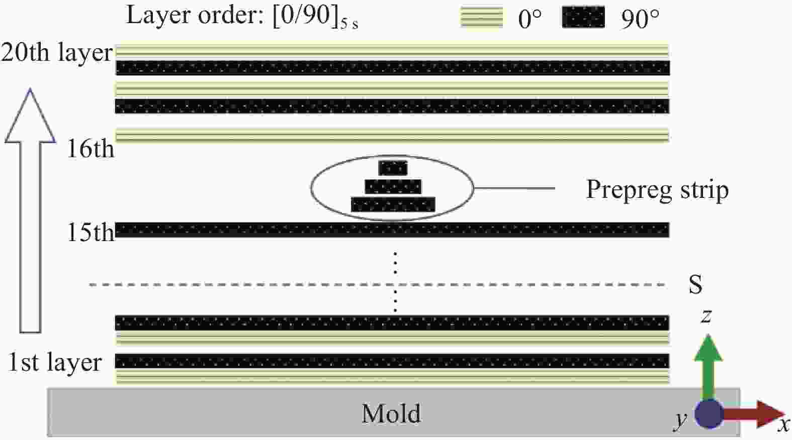
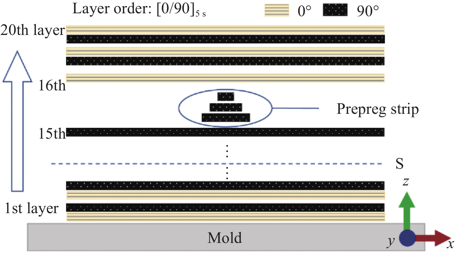
图 3 横条法制备含褶皱试样示意图
Figure 3. Wrinkled specimen manufacture using the strip-insertion method
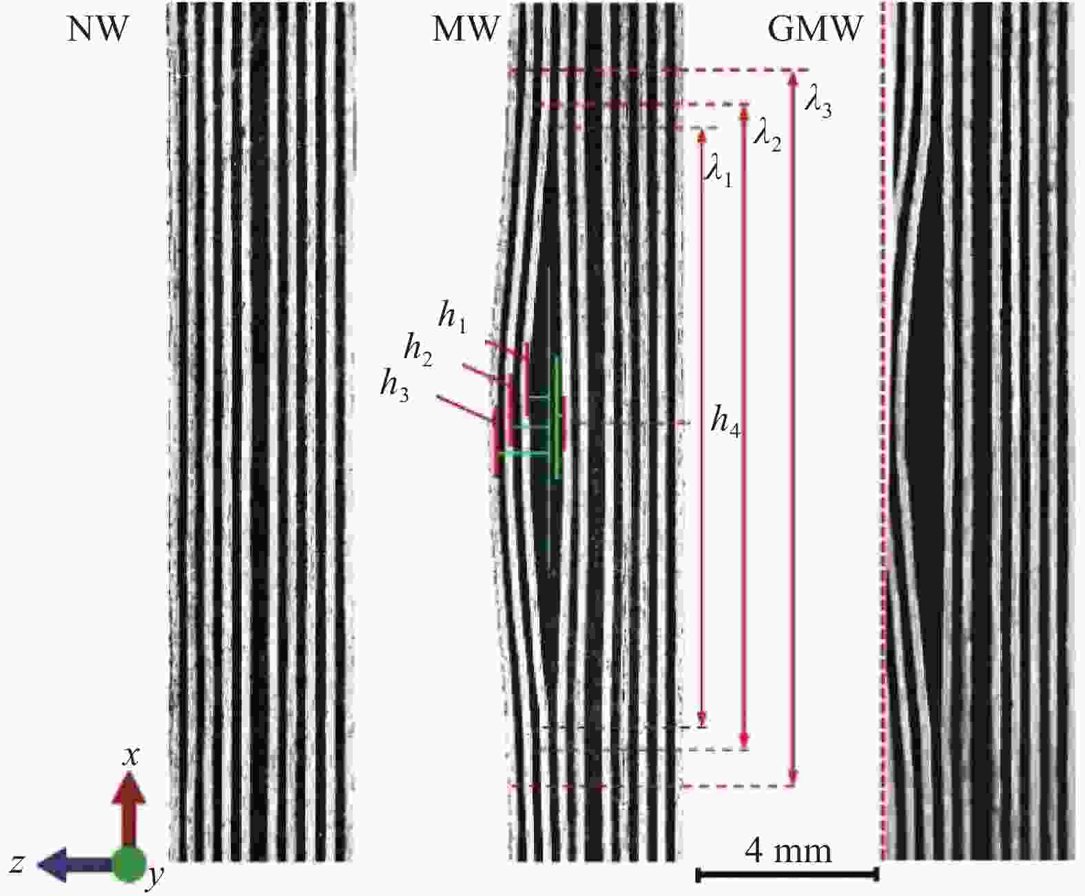
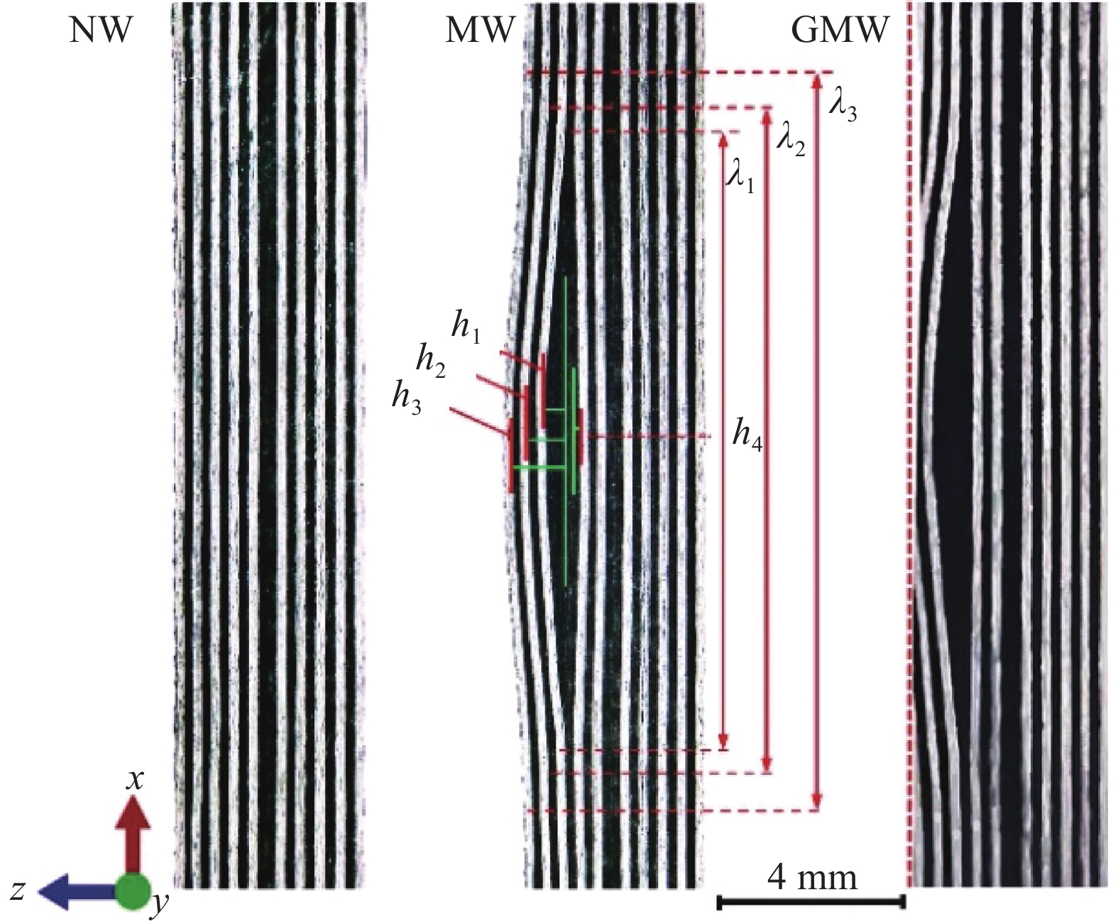
图 4 试样褶皱区域横截面形貌
Figure 4. Cross-sectional morphologies of specimen wrinkles region
NW—No wrinkle; MW—Middle wrinkle; GMW—Grinding middle wrinkle; h1—Wrinkle height of the 15th layer; h2—Wrinkle height of the 17th layer; h3—Wrinkle height of the 20th layer; h4—Wrinkle height of the 14th layer; λ1—Wavelength of the 11th layer to the 17th layer; λ2—Wavelength of the 17th layer to the 19th layer; λ3—Wavelength of the 20th layer

图 5 实验装置示意图
Figure 5. Schematic diagram of experimental device
DIC—Digital imaging correlation

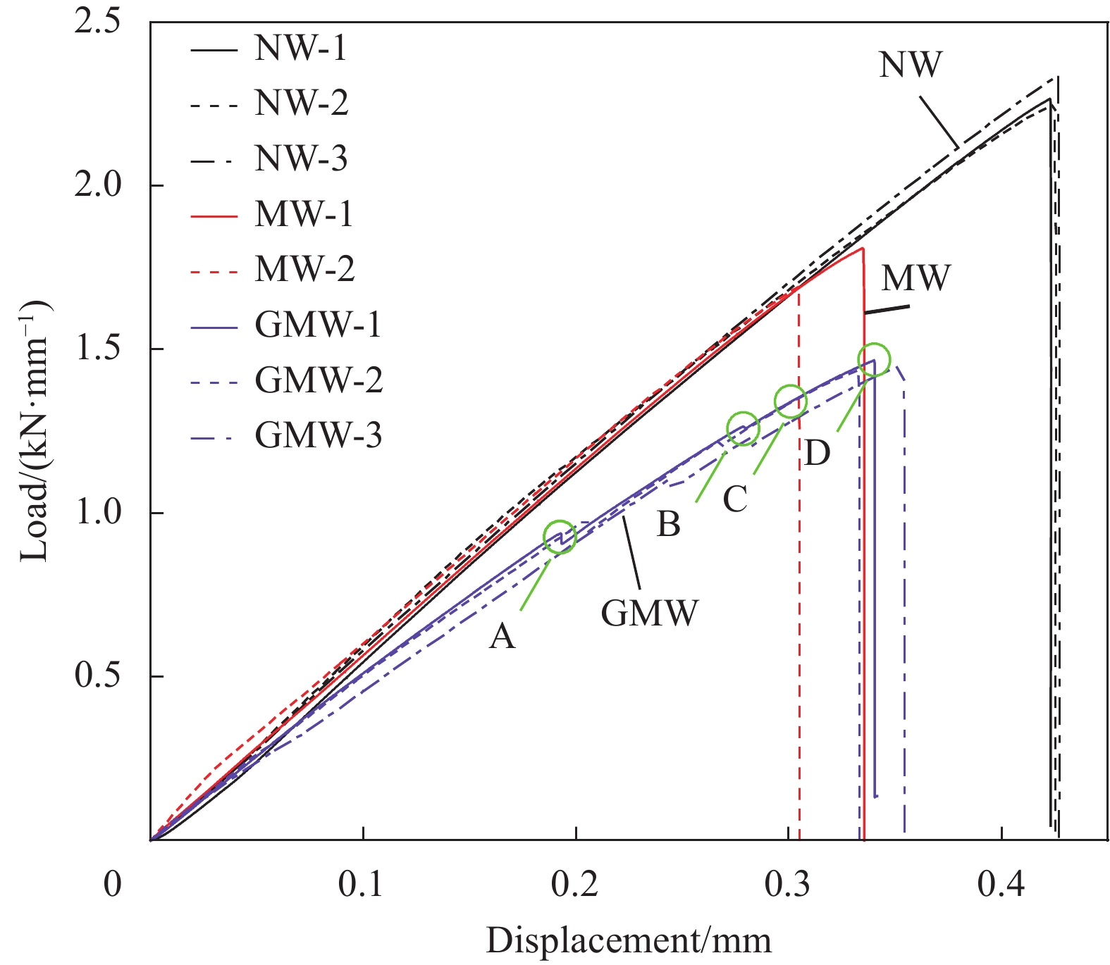
图 6 T300级碳纤维/环氧树脂正交层合板压缩位移-载荷曲线
Figure 6. Compressive displacement-load curves of T300 carbon fiber/epoxy orthogonal laminates

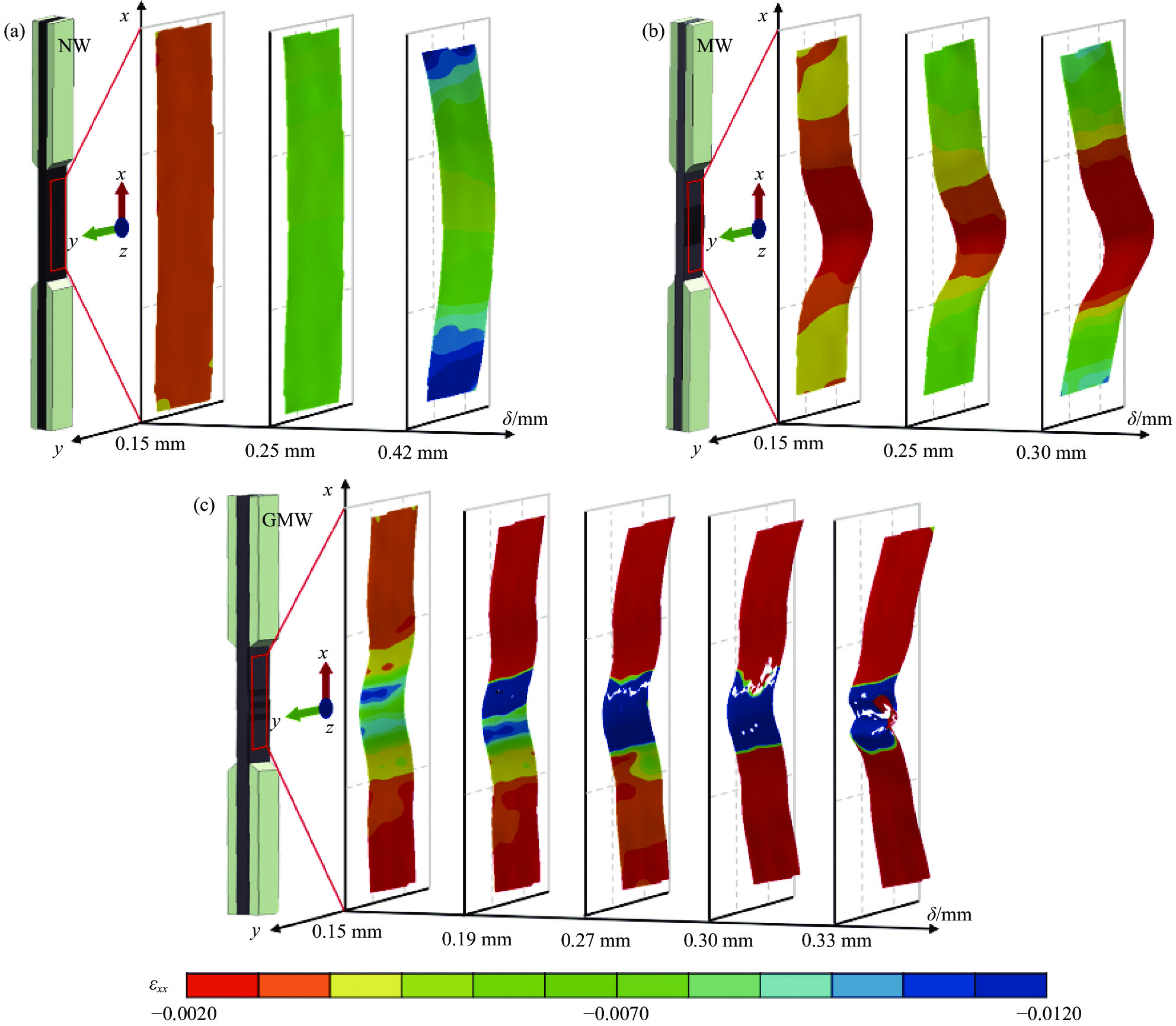
图 7 压缩过程中T300级碳纤维/环氧树脂表面应变εxx分布的演变过程:(a) NW;(b) MW;(c) GMW
Figure 7. Variation of surface strain εxx distribution of T300 carbon fiber/epoxy during compression: (a) NW; (b) MW; (c) GMW
δ—Compression displacement; εxx—Compressive strain

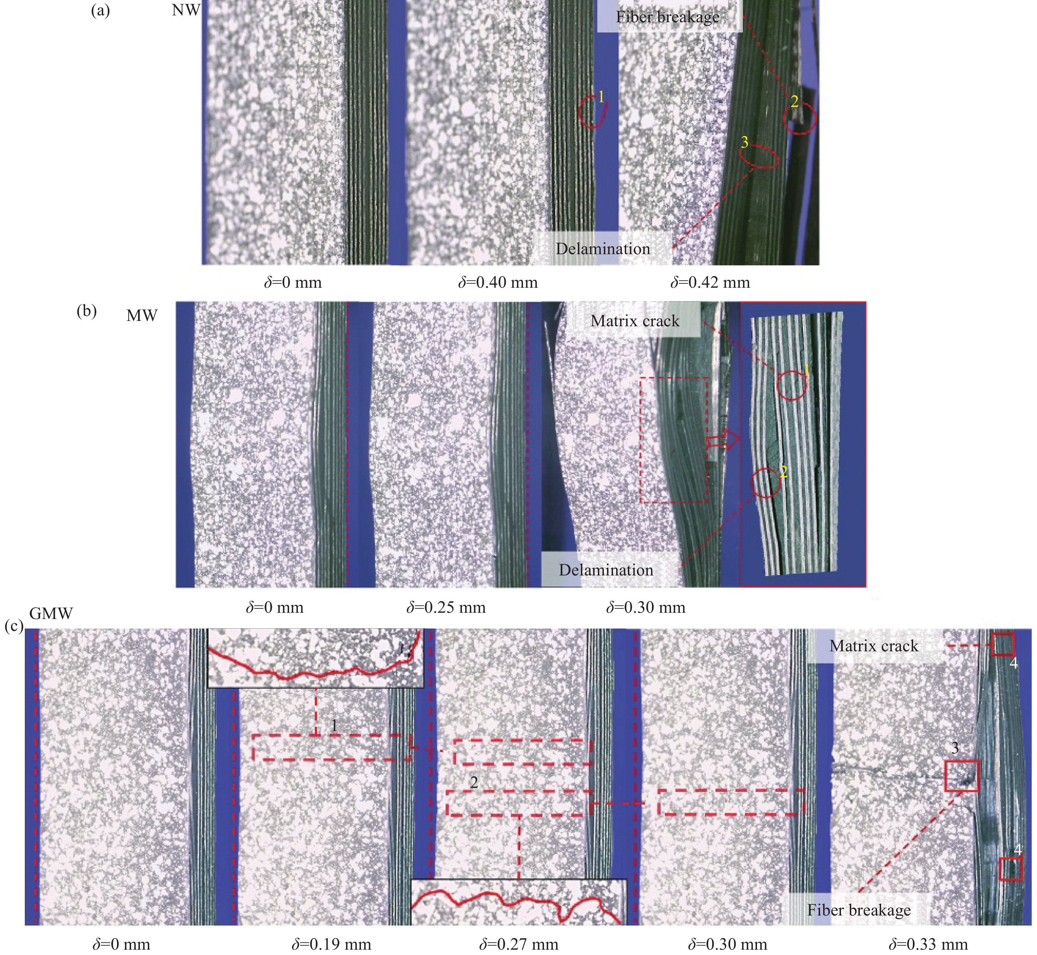
图 8 T300级碳纤维/环氧树脂试样压缩破坏过程:(a) NW;(b) MW;(c) GMW
Figure 8. Damage process of of T300 carbon fiber/epoxy samples: (a) NW; (b) MW; (c) GMW
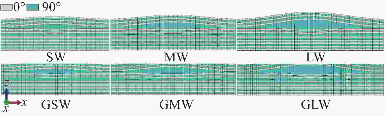
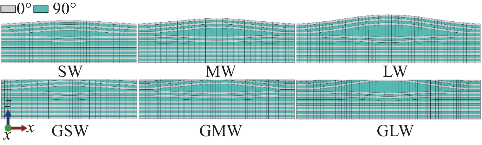
图 10 不同褶皱大小层合板模型的局部网格信息
Figure 10. Local mesh information of the different wrinkled laminate models
SW—Small Wrinkle; GSW—Grinding Small Wrinkle; LW—Large Wrinkle; GLW—Grinding Large Wrinkle
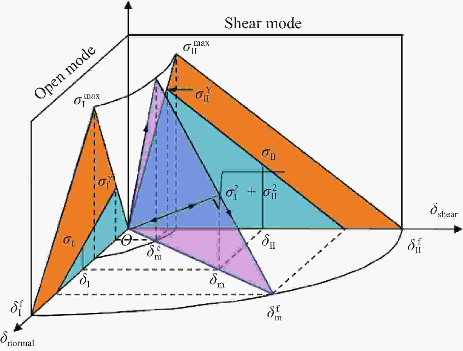
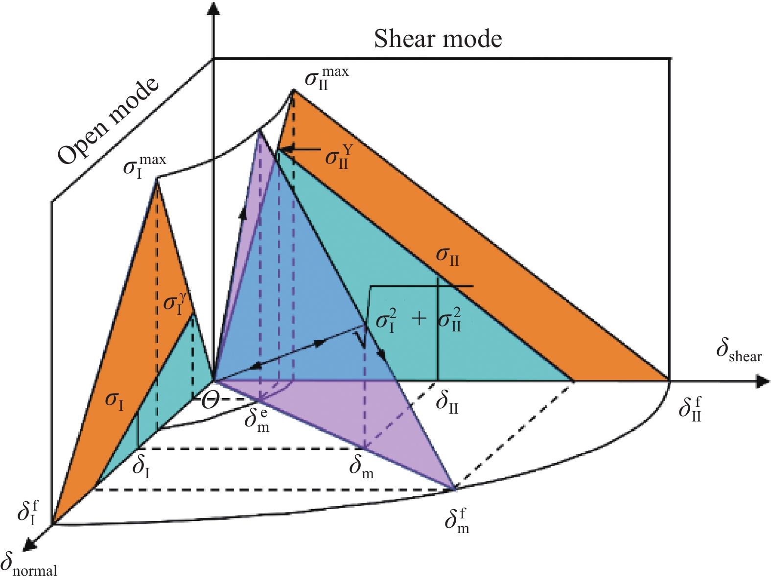
图 11 双线性混合软化本构[19]
Figure 11. Bilinear mixed-mode softening law[19]
δI f, δII f—Mode I, II relative diaplacemnet for failure; δm—Mixed-mode relative displacement ; δm e—Mixed-mode relative displacement for damage initiation; δm f—Mixed-mode relative displacement for failure; δshear—Relative displacement for Mode II; δnormal—Relative displacement for Mode I; δII—Resultant shear relative displacement; δI—Normal opening relative displacement; σI max, σII max—Mode I, II interfacial strength; σII—Shear stress resultant of interface; σI—Normal interlaminar tensile stress; σI Y, σII Y—Yield stress for Mode I, II
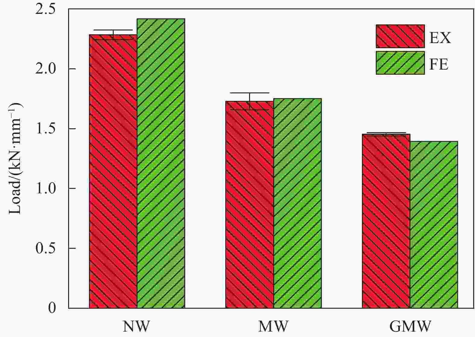
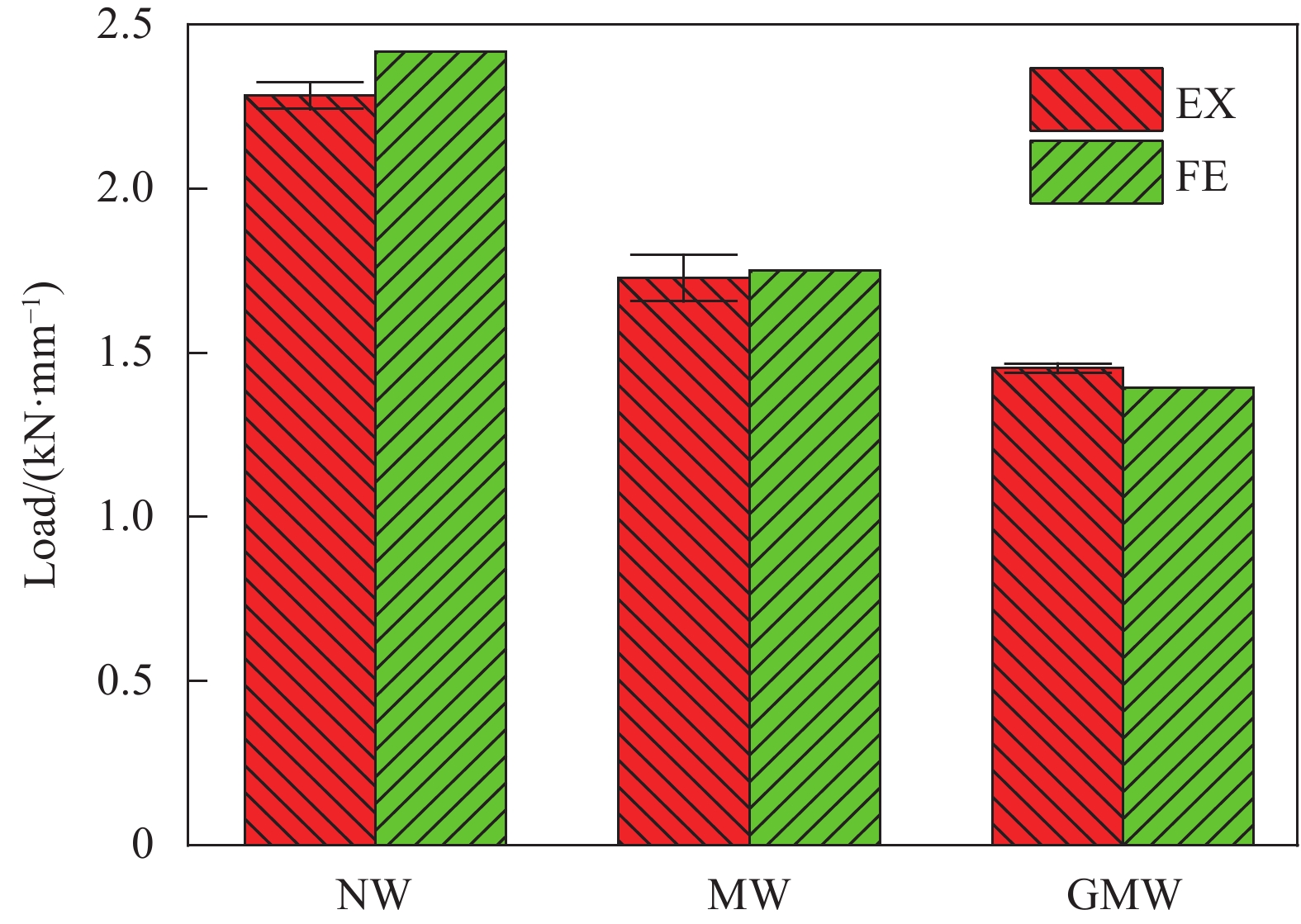
图 12 试样实验及数值模拟的压缩失效载荷
Figure 12. Experimental and numerical results of compressive failure load
EX—Experiment; FE—Finite element
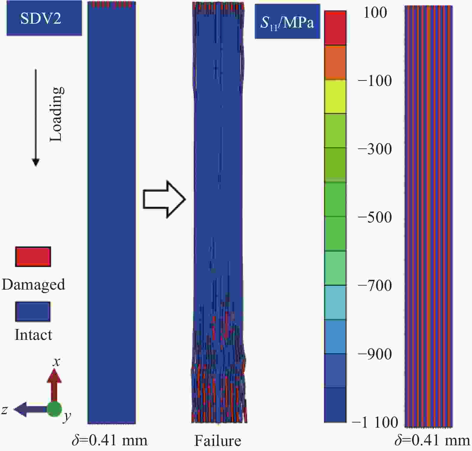
图 13 NW模型纤维压缩损伤演化与应力分布
Figure 13. Fiber compressive damage progression and stress distribution of NW model
SDV2—Fibre tensile damage state variable; S11—Longitudinal stress; δ—Compressive diaplacement

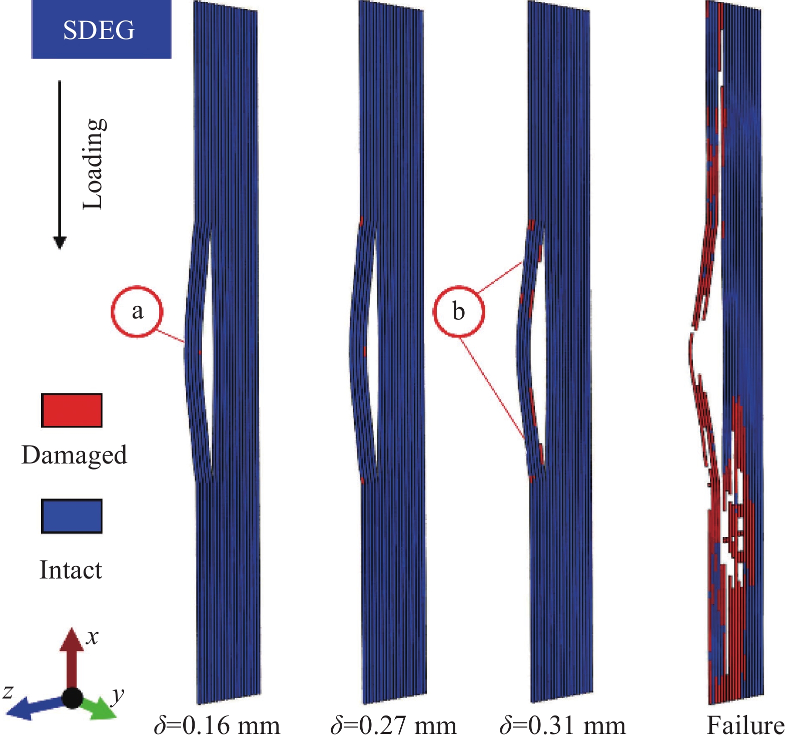
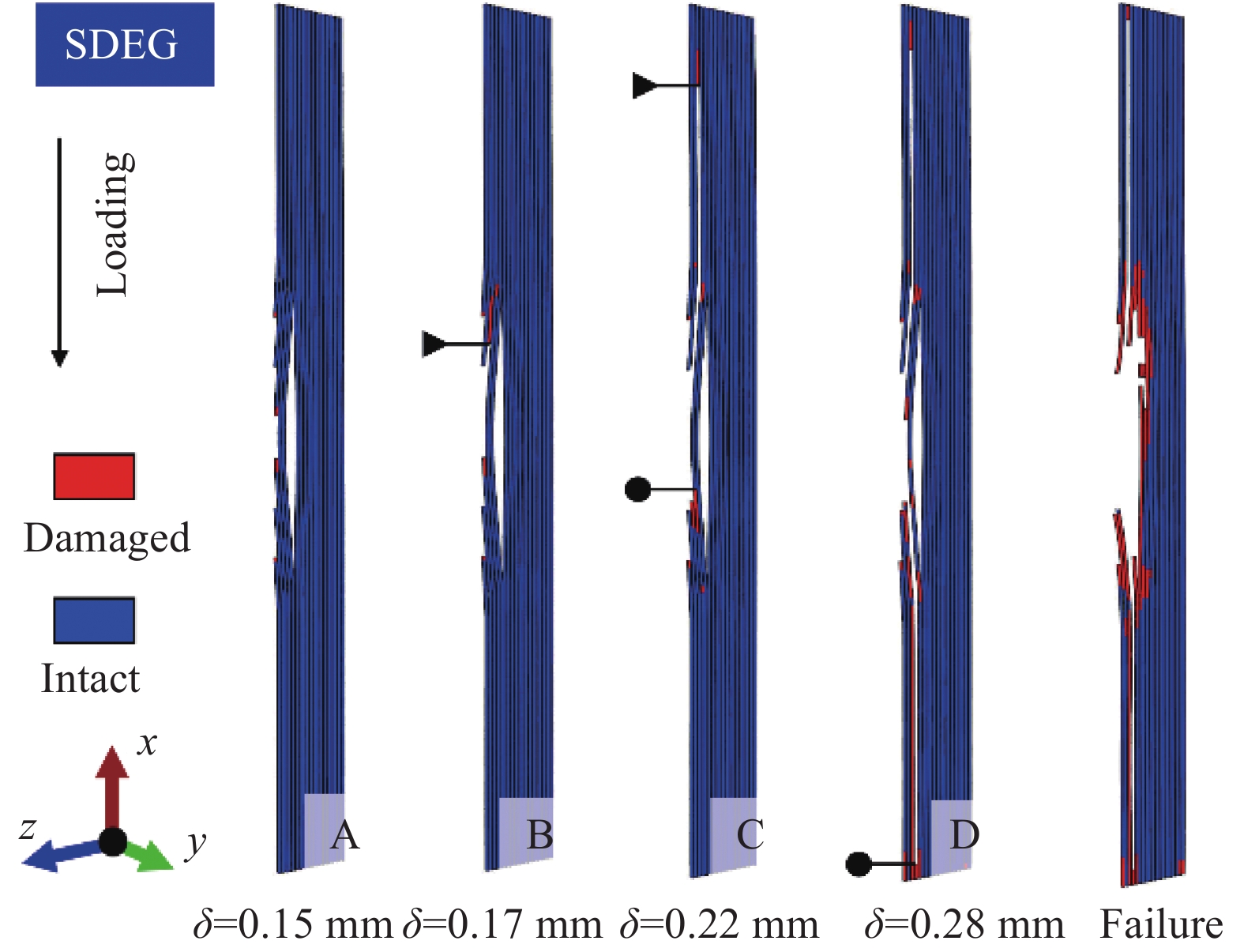
图 14 MW模型分层损伤起始与扩展
Figure 14. Delamination damage initiation and progression of MW model
SDEG—Scalar stiffness degradation variable
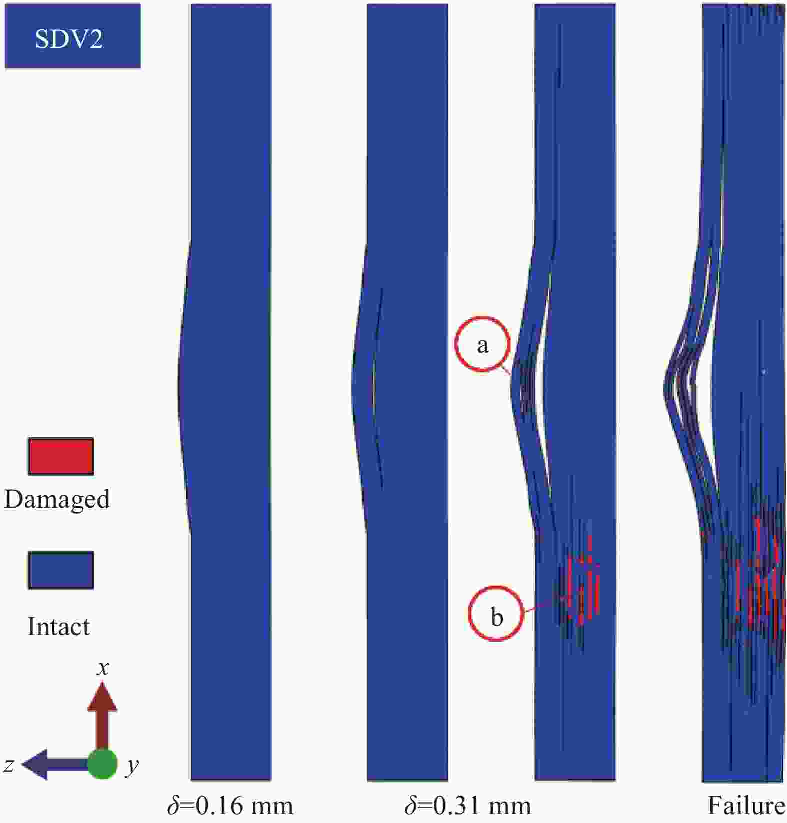
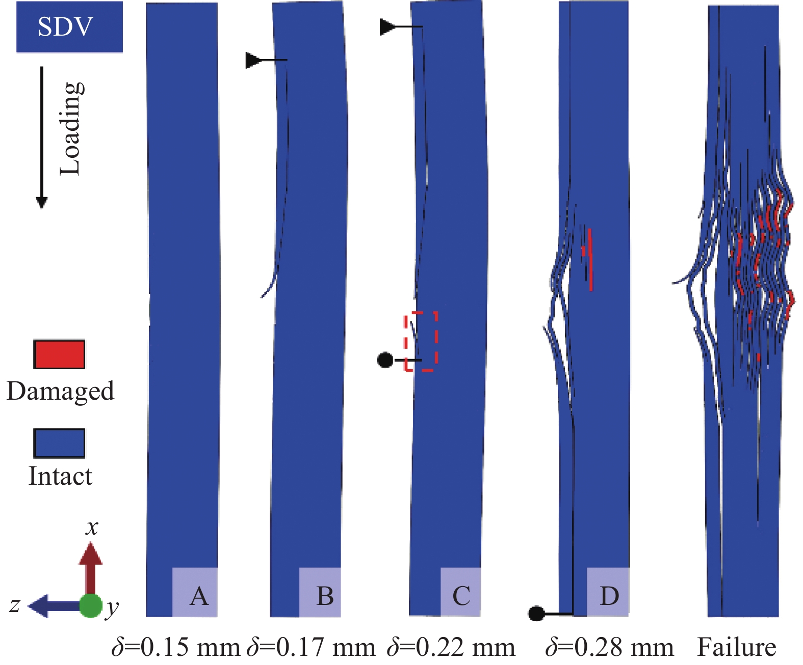
图 15 MW模型纤维损伤起始与扩展
Figure 15. Fiber and matrix damage initiation and progression of MW model

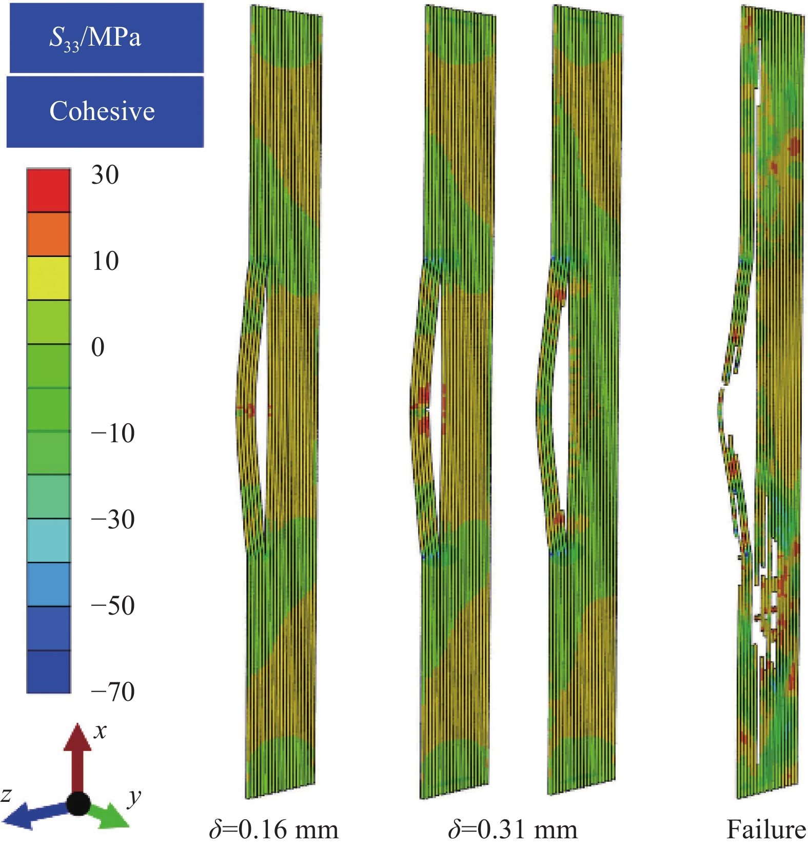
图 16 MW模型内聚力单元面外应力S33变化
Figure 16. Variation of out-plane stress S33 of cohesive element in MW model
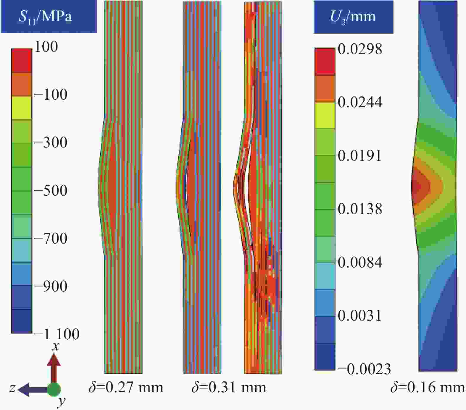
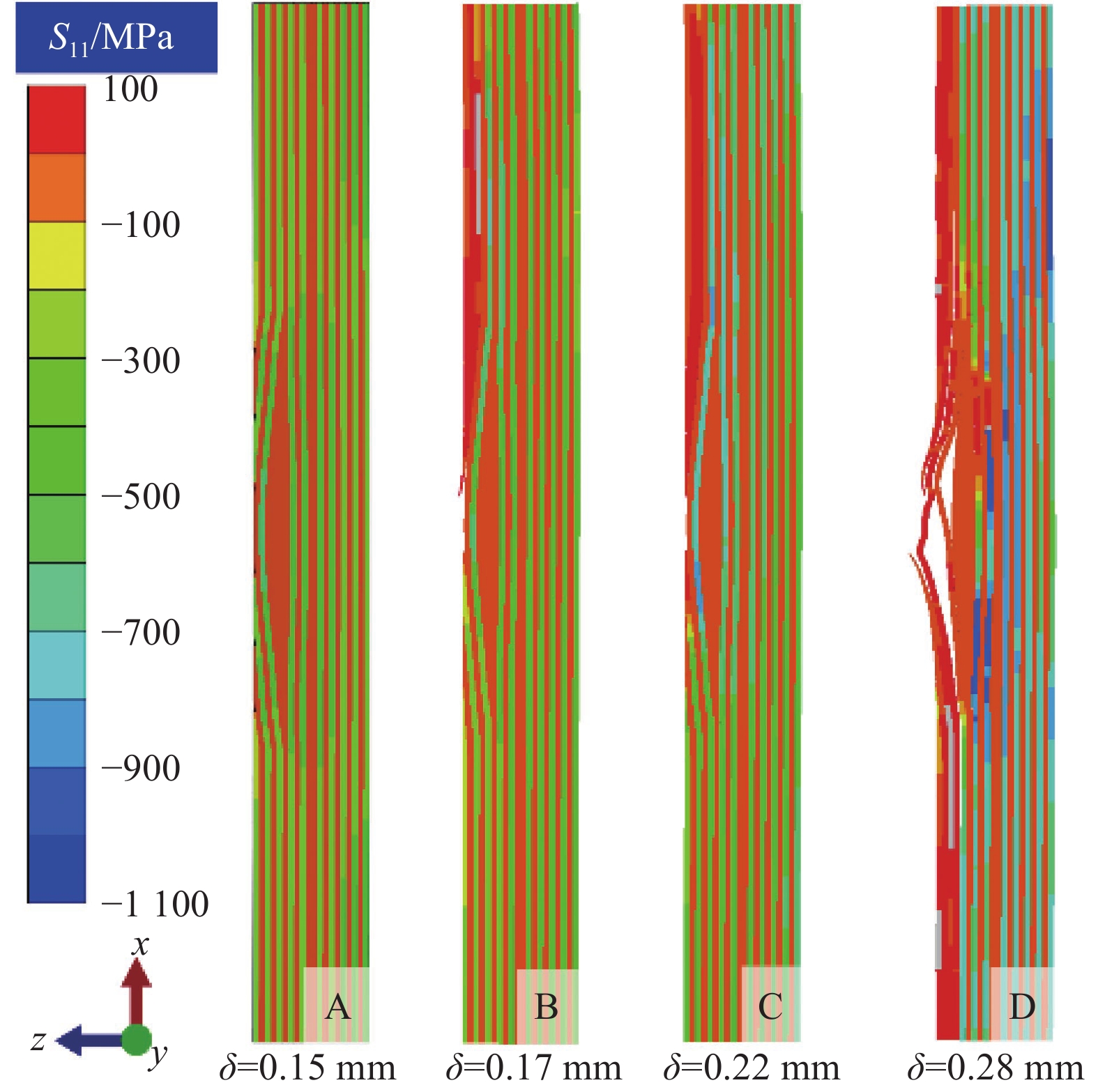
图 17 MW模型应力变化S11及面法向位移U3
Figure 17. Variation of stress S11 and out-of-plane displacement U3 in MW model

图 18 GMW试样试验和仿真载荷-位移曲线
Figure 18. Experimental and numerical load-displacement curves of GMW sample

图 19 GMW模型分层损伤起始与扩展
Figure 19. Delamination damage initiation and progression of GMW model

图 20 GMW模型纤维压缩损伤起始与扩展
Figure 20. Fiber compressive damage initiation and progression of GMW model
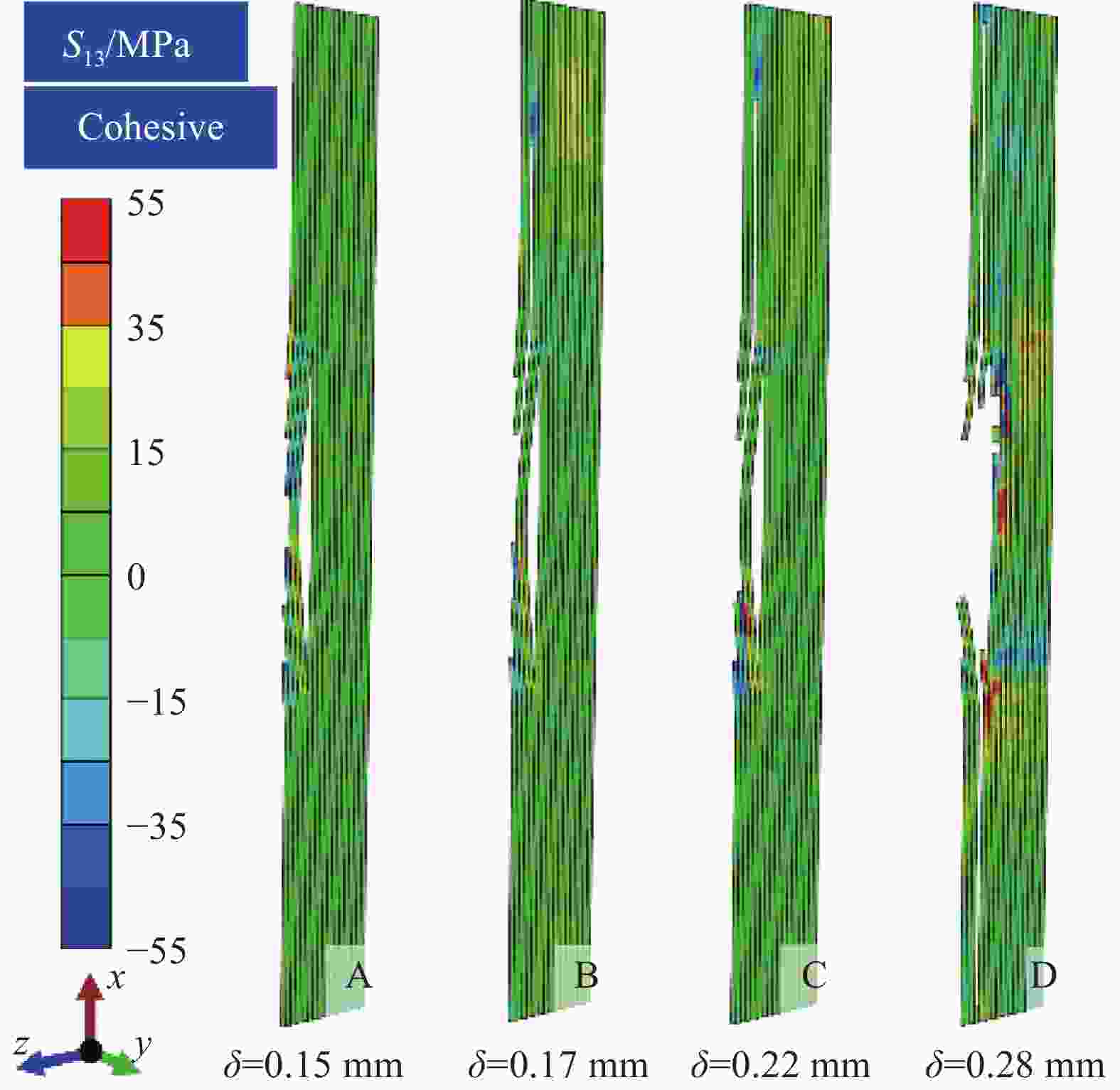
图 21 GMW模型内聚力单元应力S13变化
Figure 21. Variation of stress S13 of GMW model cohesive element
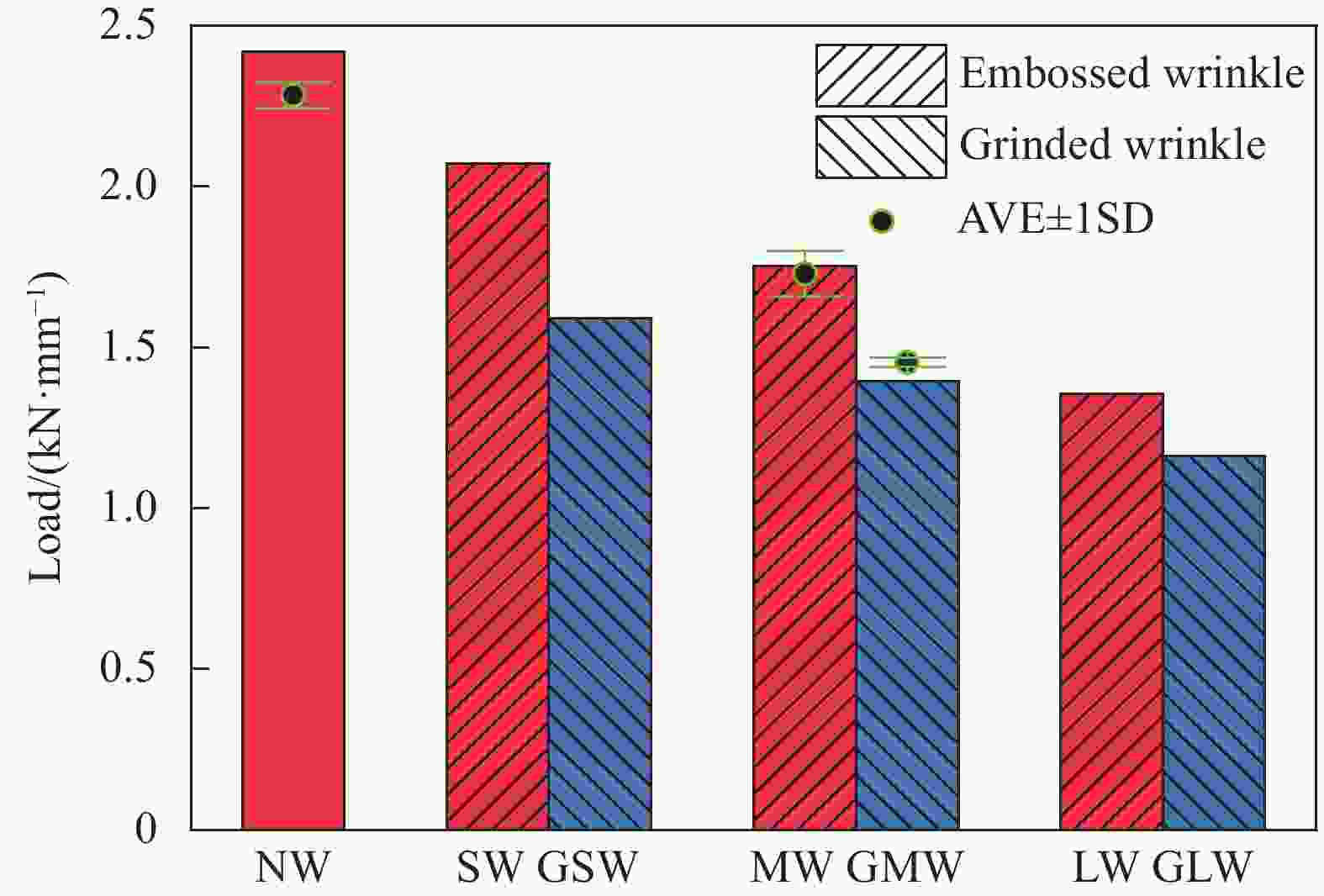
图 23 褶皱大小与压缩失效载荷
Figure 23. Wrinkle severity vs. compressive failure load
AVE—Average variance taken; SD—Standard deviation
表 1 显微图片测量褶皱参数
Table 1. Wrinkling parameters measured by microscopic images
h1
/mmh2
/mmh3
/mmh4
/mmλ1
/mmλ2
/mmλ3
/mm0.50 1.02 1.40 0.10 13.8 14.8 16.8  下载: 导出CSV
表 2 T300级碳纤维/环氧树脂正交层合板失效载荷与表观刚度
Table 2. Failure load and apparent stiffness of T300 carbon fiber/epoxy orthogonal laminates
Label F/(kN·mm−1) CV/% K/(kN·mm−2) CV/% NW 2.28 1.79 5.9 3.05 MW 1.73 4.11 5.7 1.35 GMW 1.45 1.03 4.6 2.28 Notes: F—Failure load per unit width modulus; CV—Coefficient of variation; K—Slope of F vs. displacement.
下载: 导出CSV
表 3 复合材料单向板材料参数
Table 3. Material properties of unidirectional laminate
Parameter Value Parameter Value E11/GPa 130.9 XT/MPa 1911.5 E22/GPa 7.906 XC/MPa 1100 E33/GPa 7.906 YT/MPa 38.5 ν12 0.35 YC/MPa 142.7 ν13 0.35 S/MPa 90.9 ν23 0.40 Gft/(mJ·mm−2) 133 G12/MPa 3145 Gft/(mJ·mm−2) 30 G13/MPa 3145 Gmt/(mJ·mm−2) 0.352 G23/MPa 2824 Gmc/(mJ·mm−2) 1.54 Notes: E—Elastic modulus; ν—Poisson’s ratio; G—Shear modulus; 1—Direction of fiber; 2—Direction of matrix; 3—Thickness direction of layer; XT—Longitudinal tensile strength; XC—Longitudinal compressive strength; YT—Transverse tensile strength; YC—Transverse compressive strength; S—In-plane shear strength; Gft, Gfc, Gmt, Gmc—Critical value of strain energy release rate.
下载: 导出CSV
表 4 不同大小褶皱缺陷参数
Table 4. Wrinkles defect parameter of different levels
Label SW MW LW h1/mm 0.31 0.56 0.92 h2/mm 0.70 0.97 1.37 h3/mm 1.05 1.35 1.75 h4/mm 0.11 0.07 0.09 λ1/mm 10.6 13.8 14.8 λ2/mm 13.2 14.8 15.8 λ3/mm 13.8 16.8 16.8
下载: 导出CSV
表 5 层合板层间性能
Table 5. Interlaminar properties of laminates
${K_{\text{I}}} = {K_{{\text{II}}}}$/
(N·mm−3)$\sigma _{\text{I}}^{{\text{max}}}$/
MPa$\sigma _{ {\text{II} } }^{ {\text{max} } }$/
MPa${G_{{\text{IC}}}}$/
(N·mm−1)${G_{{\text{IC}}}}$/
(N·mm−1)α 106 28 55 0.102 0.277 1.8 Notes: KI, KII—Mode I/II interfacial stiffness; GIC, GIIC—Mode I/II critical strain energy release rate; α—Empirical parameter of power law.
下载: 导出CSV
-
[1] 冯志海, 李俊宁, 田跃龙, 等. 航天先进复合材料研究进展[J]. 复合材料学报, 2022, 39(9):4187-4195.FENG Zhihai, LI Junning, TIAN Yuelong, et al. Research progress of advanced composite materials for aerospace applications[J]. Acta Materiae Compositae Sinica,2022,39(9):4187-4195(in Chinese). [2] DANGORA L M, MITCHELL C J, SHERWOOD J A. Predictive model for the detection of out-of-plane defects formed during textile-composite manufacture[J]. Composites Part A: Applied Science and Manufacturing,2015,78:102-112. doi: 10.1016/j.compositesa.2015.07.011 [3] LEMANSKI S L, SUTCLIFFE M P F. Compressive failure of finite size unidirectional composite laminates with a region of fibre waviness[J]. Composites Part A: Applied Science and Manufacturing,2012,43(3):435-444. doi: 10.1016/j.compositesa.2011.11.007 [4] KULKARNI P, MALI K D, SINGH S. An overview of the formation of fibre waviness and its effect on the mechanical performance of fibre reinforced polymer composites[J]. Composites Part A: Applied Science and Manufacturing,2020,137:106013. doi: 10.1016/j.compositesa.2020.106013 [5] LEONG M, OVERGAARD L C T, THOMSEN O T, et al. Investigation of failure mechanisms in GFRP sandwich structures with face sheet wrinkle defects used for wind turbine blades[J]. Composite Structures,2012,94(2):768-778. doi: 10.1016/j.compstruct.2011.09.012 [6] WILHELMSSON D, GUTKIN R, EDGREN F, et al. An experimental study of fibre waviness and its effects on compressive properties of unidirectional NCF composites[J]. Composites Part A: Applied Science and Manufacturing,2018,107:665-674. doi: 10.1016/j.compositesa.2018.02.013 [7] 朱俊, 吴维清, 欧阳佳斯, 等. 面外波纹对复合材料层合板弹性性能的影响[J]. 复合材料学报, 2016, 33(9):1981-1988.ZHU Jun, WU Weiqing, OUYANG Jiasi, et al. Influence of out-of-plane waviness on elastic properties of composite laminates[J]. Acta Materiae Compositae Sinica,2016,33(9):1981-1988(in Chinese). [8] LARRAÑAGA-VALSERO B, SMITH R A, TAYONG R B, et al. Wrinkle measurement in glass-carbon hybrid laminates comparing ultrasonic techniques: A case study[J]. Composites Part A: Applied Science and Manufacturing,2018,114:225-240. doi: 10.1016/j.compositesa.2018.08.014 [9] NARTEY M, ZHANG T, GONG B W, et al. Understanding the impact of fibre wrinkle architectures on composite laminates through tailored gaps and overlaps[J]. Composites Part B: Engineering,2020,196:108097. doi: 10.1016/j.compositesb.2020.108097 [10] NIMBAL S S, BANKER M M, ROOPA A, et al. Effect of gap induced waviness on compressive strength of laminated composites[J]. Materials Today:Proceedings,2017,4(8):8355-8369. doi: 10.1016/j.matpr.2017.07.179 [11] 于晓东, 胡海晓, 贾欲明, 等. 褶皱缺陷影响L型层合板失效行为: 实验和数值研究[J]. 复合材料学报, 2020, 37(8):1932-1943.YU Xiaodong, HU Haixiao, JIA Yuming, et al. Impact of wrinkle defects on failure behavior of L-shaped laminates: Experimental and numerical study[J]. Acta Materiae Compositae Sinica,2020,37(8):1932-1943(in Chinese). [12] XU X D, JONES M I, ALI H, et al. Effect of out-of-plane wrinkles in curved multi-directional carbon/epoxy laminates[J]. Composites Science and Technology,2020,197:108282. doi: 10.1016/j.compscitech.2020.108282 [13] MUKHOPADHYAY S, JONES M I, HALLETT S R. Compressive failure of laminates containing an embedded wrinkle: Experimental and numerical study[J]. Compo-sites Part A: Applied Science and Manufacturing,2015,73:132-142. doi: 10.1016/j.compositesa.2015.03.012 [14] MUKHOPADHYAY S, JONES M I, HALLETT S R. Tensile failure of laminates containing an embedded wrinkle: Numerical and experimental study[J]. Composites Part A: Applied Science and Manufacturing,2015,77:219-228. [15] 郑亦媚, 程吉, 王轩, 等. 褶皱层数对玻璃纤维层合板拉伸性能的影响[J]. 兵器材料科学与工程, 2021, 44(1):104-110.ZHENG Yimei, CHENG Ji, WANG Xuan, et al. Effect of different wrinkled layers on tensile properties of glass fiber reinforced laminates[J]. Ordnance Material Science and Engineering,2021,44(1):104-110(in Chinese). [16] BLOOM L D, WANG J, POTTER K D. Damage progression and defect sensitivity: An experimental study of representative wrinkles in tension[J]. Composites Part B: Engineering,2013,45(1):449-458. doi: 10.1016/j.compositesb.2012.05.021 [17] DNV-GL. Rotor blades for wind turbines: DNVGL-ST-0376[S]. Oslo: Det Norske Veritas, 2015. [18] BENDER J J, HALLETT S R, LINDGAARD E. Parametric study of the effect of wrinkle features on the strength of a tapered wind turbine blade sub-structure[J]. Composite Structures,2019,218:120-129. doi: 10.1016/j.compstruct.2019.02.065 [19] JIANG W G, HALLETT S R, GREEN B G, et al. A concise interface constitutive law for analysis of delamination and splitting in composite materials and its application to scaled notched tensile specimens[J]. International Jour-nal for Numerical Methods in Engineering,2007,69(9):1982-1995. doi: 10.1002/nme.1842 [20] HARPER P W, HALLETT S R. Cohesive zone length in numerical simulations of composite delamination[J]. Engi-neering Fracture Mechanics,2008,75(16):4774-4792. doi: 10.1016/j.engfracmech.2008.06.004 [21] CAMANHO P P, DAVILA C G, DE MOURA M F. Numerical simulation of mixed-mode progressive delamination in composite materials[J]. Journal of Composite Materials,2003,37(16):1415-1438. doi: 10.1177/0021998303034505 [22] ZHAO C, DONOUGH M J, PRUSTY B G, et al. Influences of ply waviness and discontinuity on automated fibre placement manufactured grid stiffeners[J]. Composite Structures,2021,256(1):113106. -

 下载:
下载:


 点击查看大图

计量
- 文章访问数: 582
- HTML全文浏览量: 280
- PDF下载量: 39
- 被引次数: 0
