Influence of fused deposition modeling and annealing heat treatment on the fiber orientation of short carbon fiber reinforced nylon 6
-
摘要:
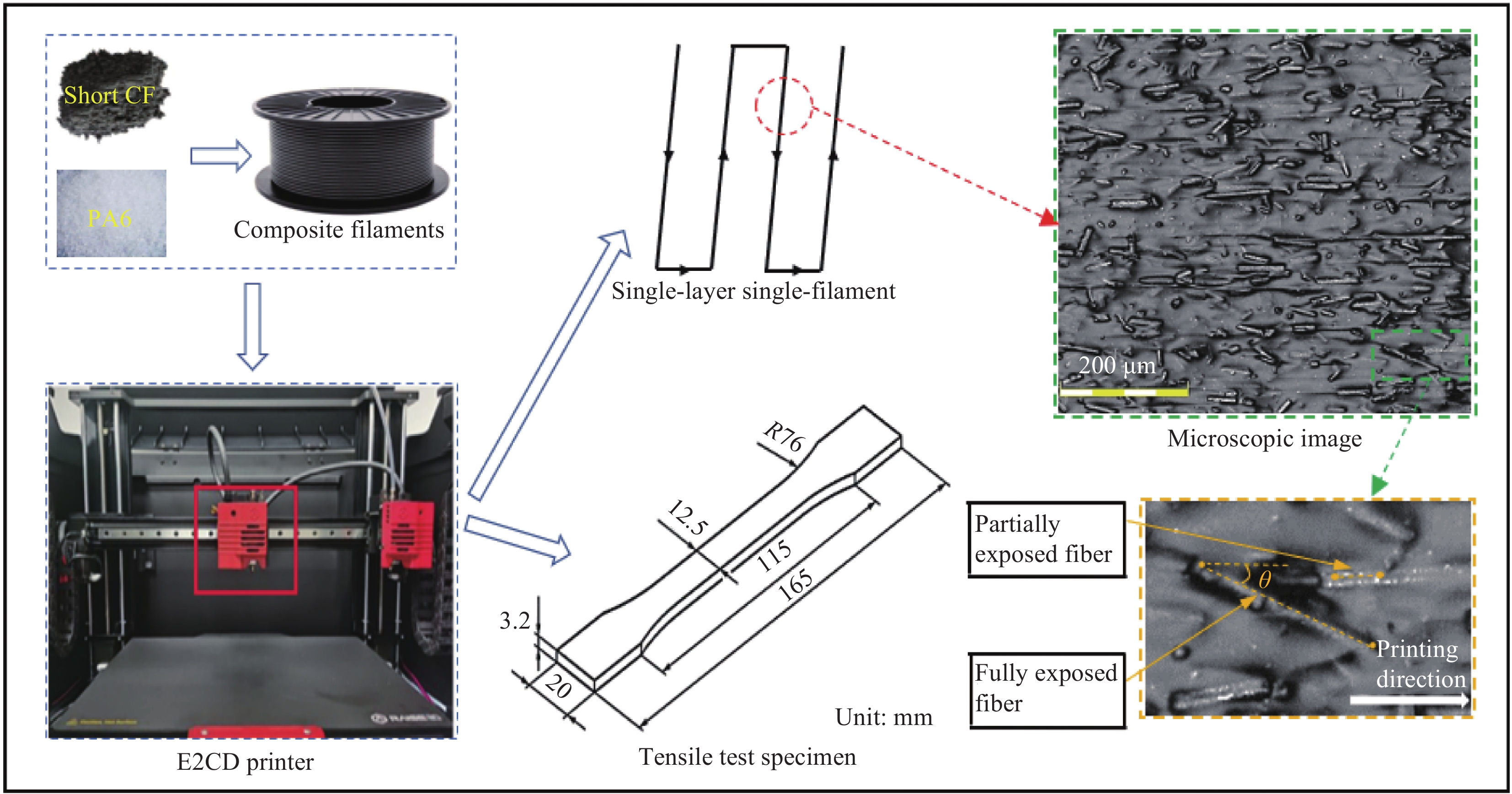
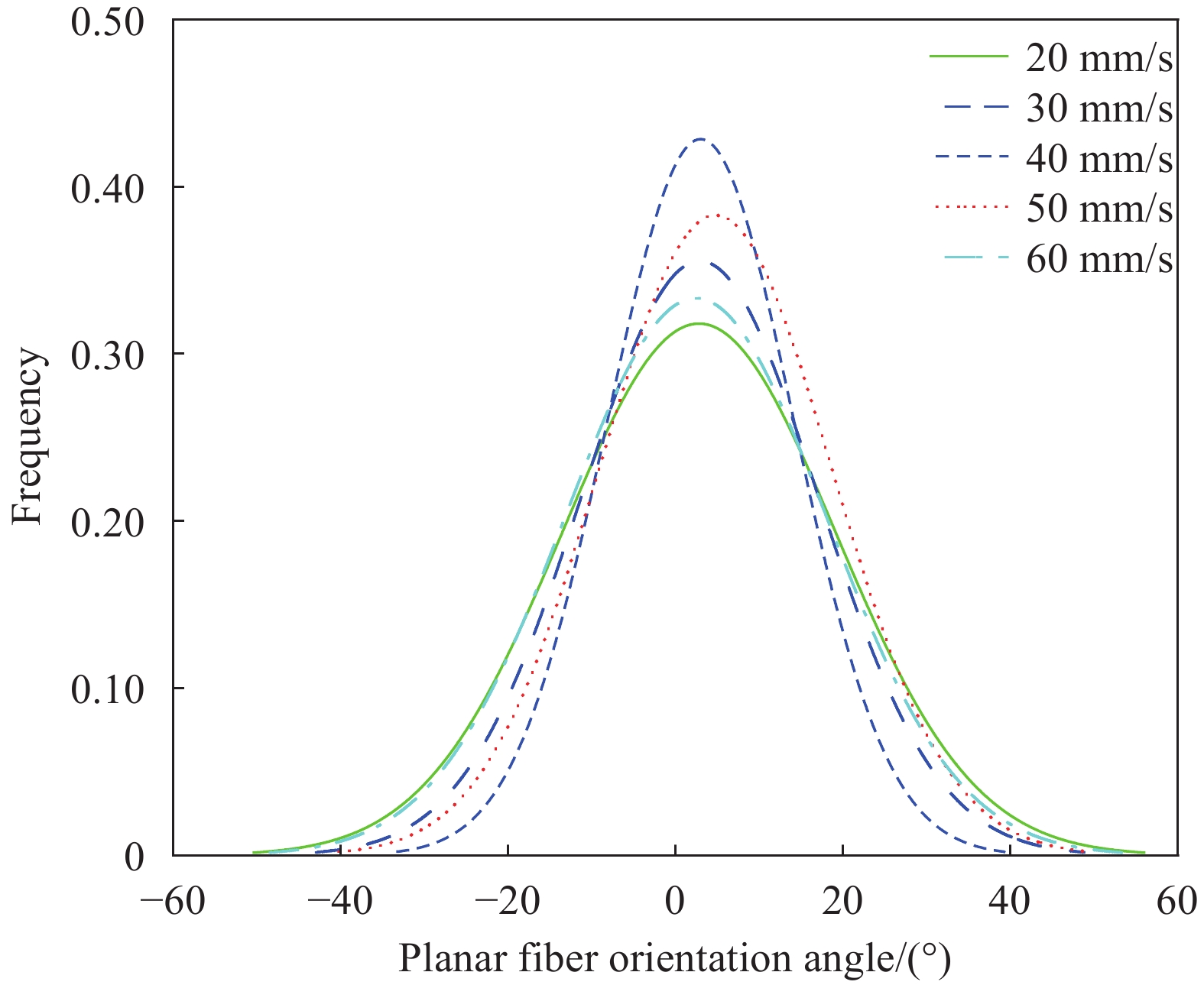
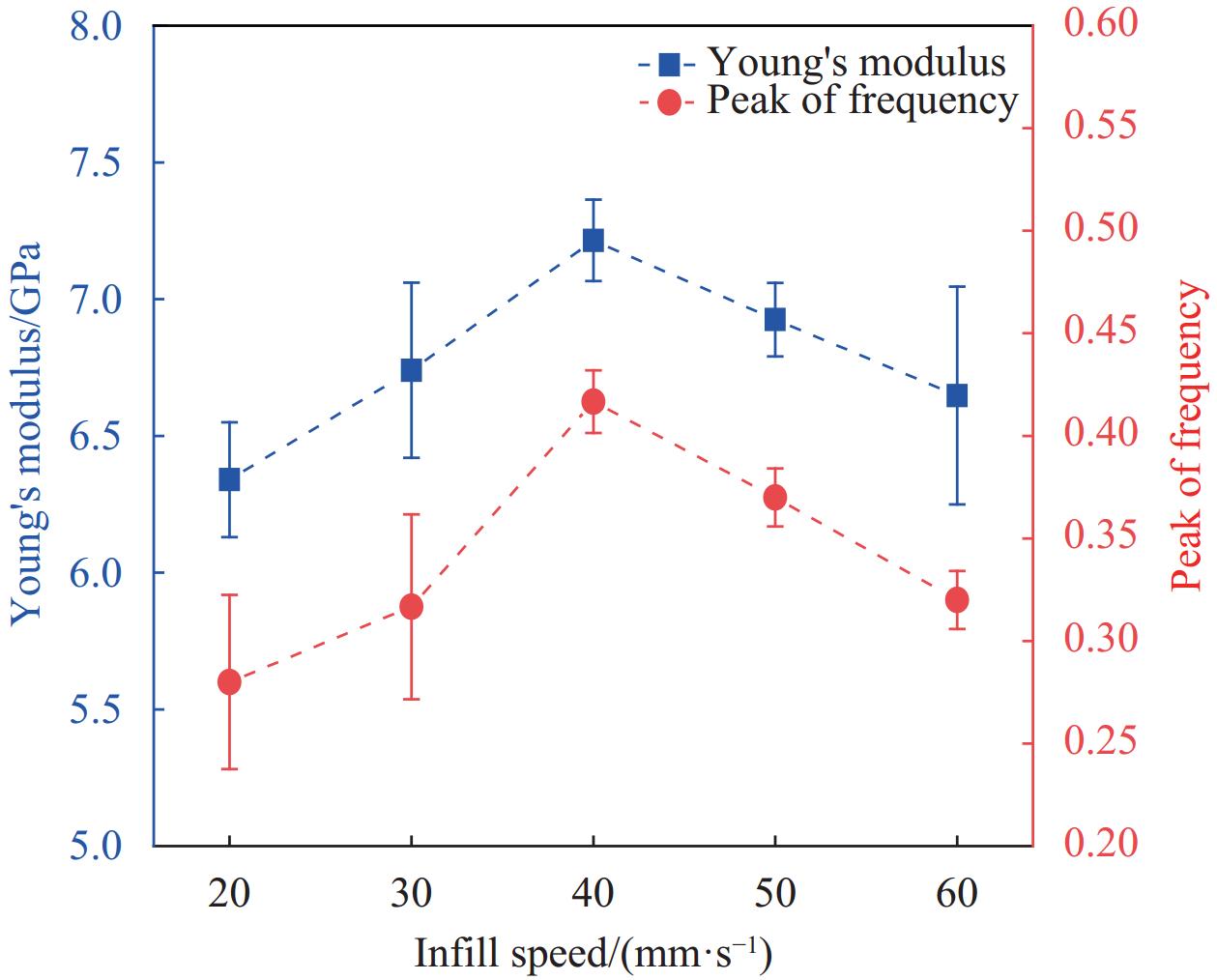
本文探究了熔融沉积成型和退火热处理的工艺参数对于短切碳纤维增强尼龙6微观纤维取向的影响,以及不同碳纤维长径比的该种材料熔融沉积成型后在纤维取向上的差异。通过在单层-单丝试样的顶面进行显微观察,使用Image J软件测量平面纤维取向角,得到不同工艺参数下的平面纤维取向分布直方图,并采用正态曲线拟合以便对比分析。实验结果显示,随着打印速度的提高,取向与打印方向保持一致的纤维数量呈先上升后下降的趋势,在V=40 mm/s时获得峰值,标准差σ为11.14,频率峰值为0.42;同时,拉伸模量也呈此变化趋势,通过Pearson相关系数计算,发现两者呈强相关,增材工艺参数对拉伸模量的影响与纤维取向的变化密切相关。纤维取向一致性并非随着加入碳纤维长径比的增大而提高,而是与制件中的保留长径比相关。不同退火温度下,当退火温度介于玻璃转化温度和结晶温度之间相对于靠近两者,对于纤维取向的影响更为显著,且在150℃下获得标准差为6.39、频率峰值为0.54的最优效果。
Abstract:The influence of process parameters in fused deposition modeling and annealing heat treatment on the microfiber orientation of short carbon fiber-reinforced nylon 6 was investigated in the study, as well as the differences in fiber orientation after fused deposition modeling for this material with varying carbon fiber slenderness ratio. Microscopic observations were conducted on single-layer-single-fiber samples, and Image J software was used to measure the planar fiber orientation angles. Histograms of planar fiber orientation under different process parameters were obtained and fitted with normal curves for comparative analysis. The experimental results indicate that with increasing printing speed, the number of fibers oriented in the printing direction first rises and then falls, reaching a peak at V=40 mm/s, with a standard deviation σ of 11.14 and a frequency peak of 0.42. Additionally, the tensile modulus follows a similar trend, and Pearson correlation analysis reveals a strong correlation between the two. Fiber orientation consistency does not improve with an increase in carbon fiber slenderness ratio, but is related to the retained slenderness ratio in the specimen. At different annealing temperatures, the impact on fiber orientation is more pronounced when the annealing temperature is between the glass transition temperature and the crystallization temperature, with the optimal effect achieved at 150℃ with a standard deviation of 6.39 and peak frequency of 0.54.
-
高模量碳纤维增强环氧树脂基复合材料由于高强度、高比刚度、耐腐蚀性等方面的理想性能在各个领域得到了广泛的应用[1-4]。但高模碳纤维因表面经高温石墨化处理,缺陷减少,含碳量增加,导致纤维表面活性较低并且与树脂基体结合不够良好[5-6]。当高模碳纤维复合材料在湿热环境下使用时这一缺陷可能更加明显。基于水分子的扩散方式以及复合材料吸湿损伤模式,研究人员在不同湿热条件下探索了碳纤维复合材料在湿热环境下的界面性能,均有所下降[7-8]。Dzul-Cervantes等[9]使用聚砜改性环氧树脂基体,并使用硅烷偶联剂3-缩水甘油醚氧基丙基三甲氧基硅烷对碳纤维进行了表面处理,处理后界面剪切强度(IFSS)提高,并且经过25%以及95%相对湿度老化后,发现IFSS保持率良好。Yu等[10]采用三甲氧基硅烷以及碳纳米管对碳纤维表面进行处理,IFSS提升了26.3%,并且在120天的模拟海水浸泡试验后,IFSS下降缓慢。
另一种方法则是采用碳纳米材料例如碳纳米管(CNT)、氧化石墨烯(GO)等对复合材料的界面进行改性,进而提升复合材料性能[11-12]。但对这些纳米粒子进行氧化与功能化处理过程中耗费成本与时间,并且对纳米粒子本体结构造成了损害[13-14],改性后的复合材料在湿热环境下使用表现一般[15]。原因在于功能化纳米粒子表面带有—COOH、 —CONH、—NH2等官能团,水分子在扩散过程中对其更加敏感,这导致了复合材料湿热性能有所下降[16]。与此不同的是,纳米石墨烯片(GNP)作为一种二维结构的纳米粒子,应用在复合材料中可以提升其界面性能,同时降低复合材料在湿热环境下的吸湿率,提高其力学性能[17-18]。Ozge等[19]研究了不同纤维素纳米晶(CNC)/GNP比例改性的纤维,其增强的复合材料层间剪切强度(ILSS)由35.5 MPa提高到45.4 MPa。
基于此,以二维纳米结构、具有片层阻隔效应的GNP为研究对象,利用CNC自身结构特性对GNP进行分散获得电泳液,采用电泳沉积技术对高模量碳纤维(HMCF)进行沉积改性,实现特性表面的构筑。研究了不同构筑条件对纤维表面及其复合材料的界面性能以及高湿热条件下(80%相对湿度、90℃温度) HMCF复合材料吸湿率与界面性能的变化,并对GNP改性高模碳纤维增强复合材料的作用机制进行讨论。
1. 实验部分
1.1 原材料
高模量碳纤维(3 K),密度为1.83 g/cm3,北京化工大学高模量碳纤维研究室;纤维素纳米晶(CNC),长度约为200 nm,外径约为10 nm,上海麦克林生化科技股份有限公司;石墨烯纳米片(GNP),纯度大于99.5%,北京翰隆达科技发展有限公司;环氧树脂(E44),南通星辰合成材料有限公司;固化剂为三乙烯四胺(TETA),上海麦克林生化科技股份有限公司;去离子水为本实验室自制。
1.2 实验过程
1.2.1 GNP电泳液的制备
为了增加GNP在水中的分散性,先在200 mL去离子水加入0.05 g CNC粉末,搅拌15 min。之后缓慢加入0.1 g GNP,搅拌15 min,采用冰水浴超声法对溶液处理2 h,下一步离心处理10 min,得到GNP浓度0.5 mg/mL的电泳液。
1.2.2 GNP改性碳纤维的制备
将550℃脱胶处理的HMCF通过装有GNP的电泳槽,以碳纤维作阳极,不锈钢电泳槽作阴极,固定电压5、10、20 V对碳纤维进行GNP的沉积,随后进行固含量1.0%水性环氧乳液上浆,分别得到GNP改性碳纤维CF-5、CF-10、CF-20。未改性的HMCF为U-CF,见表1。
表 1 各样品缩写命名Table 1. Abbreviations used for various samples preparedSample code Details U-CF Untreated commercial carbon fibers (CF) CF-5 0.5 mg/mL graphene nanoplates solution 5 V voltage electrophoresis deposited modified fibers CF-10 0.5 mg/mL graphene nanoplates solution 10 V voltage electrophoresis deposited modified fibers CF-20 0.5 mg/mL graphene nanoplates solution 20 V voltage electrophoresis deposited modified fibers U-CF/EP Untreated commercial carbon fiber reinforced epoxy (EP) composites CF-5/EP 0.5 mg/mL graphene nanoplates solution 5 V voltage electrophoresis deposited modified fibers reinforced epoxy composites CF-10/EP 0.5 mg/mL graphene nanoplates solution 10 V voltage electrophoresis deposited modified fibers reinforced epoxy composites CF-20/EP 0.5 mg/mL graphene nanoplates solution 20 V voltage electrophoresis deposited modified fibers reinforced epoxy composites Aged U-CF/EP After 30 d of hygrothermal test (90℃, 80% relative humidity (RH)) untreated commercial carbon fibers reinforced epoxy composites Aged CF-5/EP After 30 d of hygrothermal test (90℃, 80% RH) 0.5 mg/mL graphene nanoplates solution 5 V voltage electrophoresis deposited modified fibers reinforced epoxy composites Aged CF-10/EP After 30 d of hygrothermal test (90℃, 80% RH) 0.5 mg/mL graphene nanoplates solution 10 V voltage electrophoresis deposited modified fibers reinforced epoxy composites Aged CF-20/EP After 30 d of hygrothermal test (90℃, 80% RH) 0.5 mg/mL graphene nanoplates solution 20 V voltage electrophoresis deposited modified fibers reinforced epoxy composites 1.2.3 HMCF/EP复合材料的制备
将脱模剂在不锈钢模具表面均匀涂抹,以10∶1的质量比将环氧树脂E44与固化剂TETA混合均匀,得到混合物。将40%体积占比的基体混合物均匀地涂至单向排列体积占比60%的HMCF束丝表面。将HMCF模压料放入加热好的不锈钢模具中,80℃固化2 h,得到复合材料试样U-CF/EP、CF-5/EP、CF-10/EP、CF-20/EP,见表1。
1.2.4 测试与表征
使用SEM (MAIA3,TESCAN,捷克)表征HMCF以及复合材料断面微观形貌,为了避免电荷聚集,对测试的粉末、纤维及块状复合材料进行了喷金处理。使用XPS (Scientific K-Alpha,Thermo,美国)对HMCF表面化学状态进行了分析表征。
参考GB/T 30969—2014[20]方法,使用Instron 3345型万能材料试验机测试复合材料(200 mm×6 mm×2 mm)的ILSS。压头加载速率为2 mm/min,每组至少获得5个有效值。最后根据下式计算ILSS,取平均值。
ILSS=34Fbh (1) 式中:ILSS为复合材料的层间剪切强度;F为样条最大破坏载荷(N);h为试样厚度(mm);b为试样宽度(mm)。
将不同的HMCF/EP复合材料放置在高低温交变湿热试验箱(上海一恒,BPHS型)中,设置温度90℃、相对湿度(RH) 80%的湿热条件环境,湿热时长为
1440 h,每24 h (12 h湿热+12 h室温高湿度80% RH)为一组吸湿率测试周期,测试30个周期(720 h);层间剪切强度测试选择湿热时长为0、240、480、720、1440 h复合材料试样。2. 结果与讨论
2.1 HMCF形貌
图1为不同处理情况下HMCF的表面形貌图。当GNP浓度固定为0.5 mg/mL时,电压在5 V及10 V处理情况下(图1(b)和图1(c)),纤维表面存在很多小尺寸颗粒的GNP粒子,分布较为均匀并且形成了微小凸起结构;电压在20 V的情况下(图1(d)),纤维表面就会出现粒子团聚的现象,表明电压增大会导致沉积粒子过多,电泳液中的GNP堆叠成块状与片状形貌。
2.2 HMCF表面化学状态
为了确定不同HMCF表面化学状态,对处理后不同纤维进行了XPS测试,不同HMCF的XPS广谱以及C1s峰拟合图如图2所示。
表2给出了不同HMCF的C1s特征峰结合能及相对含量信息。可以看到,经电泳沉积处理后HMCF表面C—O含量达到4.65wt%,有小幅提升,同时—COOH含量也有略微增长,达3.78wt%。主要是由于CNC侧端—OH引入,以及电泳沉积过程中碳纤维表面—COOH的形成[21]。
表 2 不同HMCF C1s特征峰结合能及相对含量Table 2. C1s characteristic peak binding energy and relative content of different HMCFFunctional group Binding energy/eV U-CF/wt% CF-5/wt% CF-10/wt% CF-20/wt% C—C 284.4 46.60 48.31 49.36 44.56 C—H 285.2 48.78 46.08 46.59 45.76 C—O 286.3 2.19 2.69 1.35 4.65 C=O 287.3 — — — — COOH 288.6 0.72 1.70 3.79 3.78 2.3 HMCF/EP复合材料界面性能
将不同改性纤维制成碳纤维增强复合材料,测试ILSS,结果如图3所示。在0~10 V电压的电场条件下改性的HMCF,其复合材料ILSS随电泳沉积电场电压增大而升高,经10 V电压电泳沉积GNP的HMCF,ILSS达到最高值75.6 MPa。此后,增大处理电压,所得HMCF复合材料的界面性能呈下降趋势。
为探究GNP电泳沉积不同处理电压处理的HMCF/EP复合材料受到切应力载荷时的界面失效的机制,采用SEM对复合材料样品的横截面形貌进行了扫描,结果如图4所示。
从图中看到,纤维与基体之间的间隙降低,断面表面树脂碎屑增加,表明电泳沉积方式将GNP引入HMCF表面增加了纤维与环氧树脂基体的物理作用。当处理电压为5 V时(图4(b)),基体间裂纹增多。当电压增大到10 V时横截面如图4(c)所示,树脂基体裂纹进一步增加,此时复合材料受载荷时应力传递较好。电压持续增大到20 V时横截面如图4(d)所示,纤维拔出情况增加,说明随着沉积电场电压增大,GNP粒子发生严重的团聚(图1(d)),从而影响了HMCF/EP界面结构,引起ILSS下降。
2.4 HMCF/EP复合材料湿热性能
在温度90℃、相对湿度80%的条件下,各复合材料湿热过程中吸湿率随时间变化如表3所示。
复合材料吸湿的初始阶段可以用菲克扩散定律描述[22]。在第二阶段吸湿速率下降,继续受到湿热因素的影响,采用两阶段扩散模型[23]进行了拟合。复合材料的吸湿率通过式(2)得到,扩散系数D通过式(3)得到,最后经式(4)拟合可得出参数k、M1∞。
Mt=Wt−W0W0 (2) D=π(h4M∞)2(Mt1−Mt2√t1−√t2)2 (3) Mt=M1∞(1+k√t){1−exp[−7.3(Dth2)0.75]} (4) 式中:Mt为t时刻复合材料的吸湿率;Wt为t时刻复合材料试样质量(g);W0为复合材料试样未湿热时质量(g);M∞为复材Fick饱和吸湿率;M1∞为复材Fick第一阶段饱和吸湿率;k为树脂弛豫常数(mm/h1/2);h为试样厚度(mm);D为扩散系数(mm/h)。
表 3 90℃、80% RH湿热条件下HMCF/EP的吸湿率Table 3. Moisture absorption of HMCF/EP at 90℃, 80% RHSample M5 d/% M10 d/% M15 d/% M20 d/% M25 d/% M30 d/% U-CF 0.08 0.16 0.21 0.24 0.25 0.26 CF-10/EP 0.07 0.15 0.19 0.21 0.22 0.24 CF-20/EP 0.08 0.17 0.22 0.22 0.24 0.25 Note: Mx d—Moisture absorption of composite material after x days. 通过运用第一与第二吸湿阶段的曲线切线相交所对应的纵坐标也同样可以获得M1∞[24]。图5为不同复合材料Fick扩散拟合曲线图。
从图中可以看出,复合材料吸湿率随湿热时间增加而增加。湿热初期,复合材料表面的空隙以及基体之间的缺陷及裂纹会加速水分子的扩散。随后基体吸湿接近饱和,逐渐出现树脂弛豫现象[25]。
表4给出了复合材料吸湿过程中的拟合参数。相比U-CF/EP的水分子扩散系数(15.7×10−4 mm/h),CF-10/EP与CF-20/EP的水分子扩散系数分别为14.8×10−4 mm/h与15.1×10−4 mm/h,表明HMCF经GNP表面改性后,界面处的GNP阻碍了水分子扩散。U-CF/EP的Fick第一阶段饱和吸湿率(M1∞)为0.12%,而电泳沉积改性纤维后复材的M1∞无明显变化。经GNP界面改性的纤维复合材料30天所达到的最大吸湿率(M30 d)与k均有所降低,进一步说明,GNP改性HMCF降低了复合材料的吸湿率。复合材料湿热过程中层间剪切强度随时间变化信息如表5所示。
表 4 80% RH、90℃湿热老化HMCF/EP吸湿拟合参数Table 4. Hygroscopic fitting parameters of HMCF/EP for hygrothermal at 90℃, 80% RHD/
(10−4 mm·h−1)M1∞/% M30 d/% k/
(10−2 mm·h−1/2)R2 CF-10/EP 14.82 0.12 0.24 4.43 0.96 CF-20/EP 15.13 0.14 0.25 3.89 0.95 U-CF/EP 15.69 0.12 0.26 5.19 0.97 Notes: D—Diffusion coefficient of water molecules in composites; M1∞—Saturated moisture absorption rate of the first stage of the composite Fick; M30 d—Moisture absorption of composite material after 30 d; k—Constant related to the relaxation of resin structure; R2—Coefficient of determination. 为研究湿热时间对复合材料界面结合的影响,选取代表性样品CF-10/EP,采用SEM手段分别对复合材料湿热不同时长的纵截面进行了表征,如图6所示。可以看出,CF-10/EP复合材料随湿热时间增加,其基体的裂纹数量从密集转为稀疏,裂纹的尺寸降低,说明随着湿热时间的增加,复合材料吸湿率逐步提高,基体产生了更多缺陷,降低了界面结合效果,减弱了复合材料受载荷时的应力传递效率。
表 5 80% RH、90℃下HMCF/EP老化过程中层间剪切强度Table 5. Interlaminar shear strength during HMCF/EP aging at 90℃, 80% RHSample ILSS0 d/
MPaILSS10 d/
MPaILSS20 d/
MPaILSS30 d/
MPaILSS60 d/
MPaU-CF/EP 69.5 68.6 65.4 64.4 61.3 CF-10/EP 75.6 73.2 69.3 69.5 67.8 CF-20/EP 72.2 68.9 68.1 66.7 65.5 Note: ILSSx d—Interlaminar shear strength of composite material after x days. 对U-CF/EP、Aged U-CF/EP、CF-10/EP、Aged CF-10/EP、CF-20/EP和Aged CF-20/EP纵断面进行观察,结果如图7所示。未经湿热试验的U-CF/EP (图7(a))、CF-10/EP (图7(b))与CF-20/EP (图7(c))基体的裂纹密度较高,说明纤维与基体结合较好,应力传递效果良好。经湿热30天后的纵断面,如图7(a1)~7(c1)所示,复合材料中均出现了孔洞,Aged U-CF/EP产生的孔洞主要分布在树脂基体中,尺寸较大,容易产生应力集中现象,此时树脂受湿热耦合作用影响较大。GNP改性复合材料缺陷出现在界面处,此时GNP周围树脂吸湿,缺陷密集且细小。
![]() 图 7 不同HMCF/EP复合材料轴向截面形态SEM图像:(a) U-CF/EP;(a1) Aged U-CF/EP;(b) CF-10/EP;(b1) Aged CF-10/EP;(c) CF-20/EP;(c1) Aged CF-20/EPFigure 7. SEM images of axial cross-section morphology of different HMCF/EP composites: (a) U-CF/EP; (a1) Aged U-CF/EP; (b) CF-10/EP; (b1) Aged CF-10/EP; (c) CF-20/EP; (c1) Aged CF-20/EP
图 7 不同HMCF/EP复合材料轴向截面形态SEM图像:(a) U-CF/EP;(a1) Aged U-CF/EP;(b) CF-10/EP;(b1) Aged CF-10/EP;(c) CF-20/EP;(c1) Aged CF-20/EPFigure 7. SEM images of axial cross-section morphology of different HMCF/EP composites: (a) U-CF/EP; (a1) Aged U-CF/EP; (b) CF-10/EP; (b1) Aged CF-10/EP; (c) CF-20/EP; (c1) Aged CF-20/EP2.5 GNP改性HMCF的增强机制
HMCF/EP的ILSS与吸湿率结果表明,GNP引入纤维表面后,复合材料层间剪切强度提高,吸湿率下降,湿热结束后(80% RH、90℃,60 d)层间剪切性能达67.8 MPa。基于复合材料的界面受剪切失效机制,对GNP增强界面强度的机制进行了探讨。图8为U-CF/EP、CF-10/EP与CF-20/EP在界面处存在的GNP影响下剪切失效示意图。
由于U-CF表面相对光滑,粗糙度低,与树脂的相互作用不强,U-CF/EP (图8(a))在受切应力时表现出不好的界面性能,在湿热环境中吸湿率较高。采用GNP构筑HMCF特性表面时,适宜的改性条件会使得GNP在纤维表面分布较为均匀,GNP对树脂与纤维间产生机械啮合作用,加之CNC与电泳沉积引入的—OH与—COOH提高了纤维活性,进一步增强了界面结合。在受到剪切作用力时,界面处产生的细小微裂纹会沿不同方向传播(图8(b)),表现出材料界面性能有所提高。相容性更佳的界面协同均匀分散的GNP片层的阻隔作用,抑制了水分子进入与扩散,进而降低了复合材料的吸湿率。当电泳沉积电压较高时,HMCF表面GNP产生团聚、分散不均匀,导致复合材料界面处存在较多孔隙、裂纹(图8(c)),一方面降低了HMCF与树脂基体的结合性,层间剪切强度下降;另一方面在湿热环境中阻隔水分子的能力下降,复合材料吸湿率升高。
3. 结 论
(1)以电泳沉积技术在高模量碳纤维(HMCF)表面引入石墨烯纳米片(GNP)后,HMCF/环氧树脂(EP)复合材料层间剪切强度由69.5MPa提升到了75.6 MPa。
(2)与未改性HMCF/EP复合材料相比,GNP电泳沉积改性HMCF/EP复合材料在90℃、80%相对湿度(RH)湿热环境中存放30天,吸湿率由0.26%下降到0.24%,扩散系数从15.7×10−4 mm/h下降到14.8×10−4 mm/h。存放达60天后,ILSS仍保持在67.8 MPa,具有较好耐湿热性能。
(3) GNP在高模碳纤维复合材料界面均匀分布,增强了纤维与树脂间的机械啮合作用,提高了应力传递效率。同时GNP阻碍了水分子的扩散,减小了湿热耦合作用对复合材料的损伤。
-
图 3 (a)不同打印速度(V)下CF270-PA6试样的显微图像和平面纤维取向分布;V从20 mm/s到60 mm/s下的显微图像:(b) V=20 mm/s;(c) V=30 mm/s;(d) V=40 mm/s;(e) V=50 mm/s;(f) V=60 mm/s
Figure 3. (a) Microscopic images and planar fiber orientation distribution of CF270-PA6 samples at different printing speeds (V); Micrographs for V from 20 mm/s to 60 mm/s are presented: (b) V=20 mm/s; (c) V=30 mm/s; (d) V=40 mm/s; (e) V=50 mm/s; (f) V=60 mm/s
表 1 材料参数
Table 1 Material parameters
Material Matrix
materialReinforced
phaseMean fiber
diameter/
μmMean fiber
length/
mmFiber
aspect
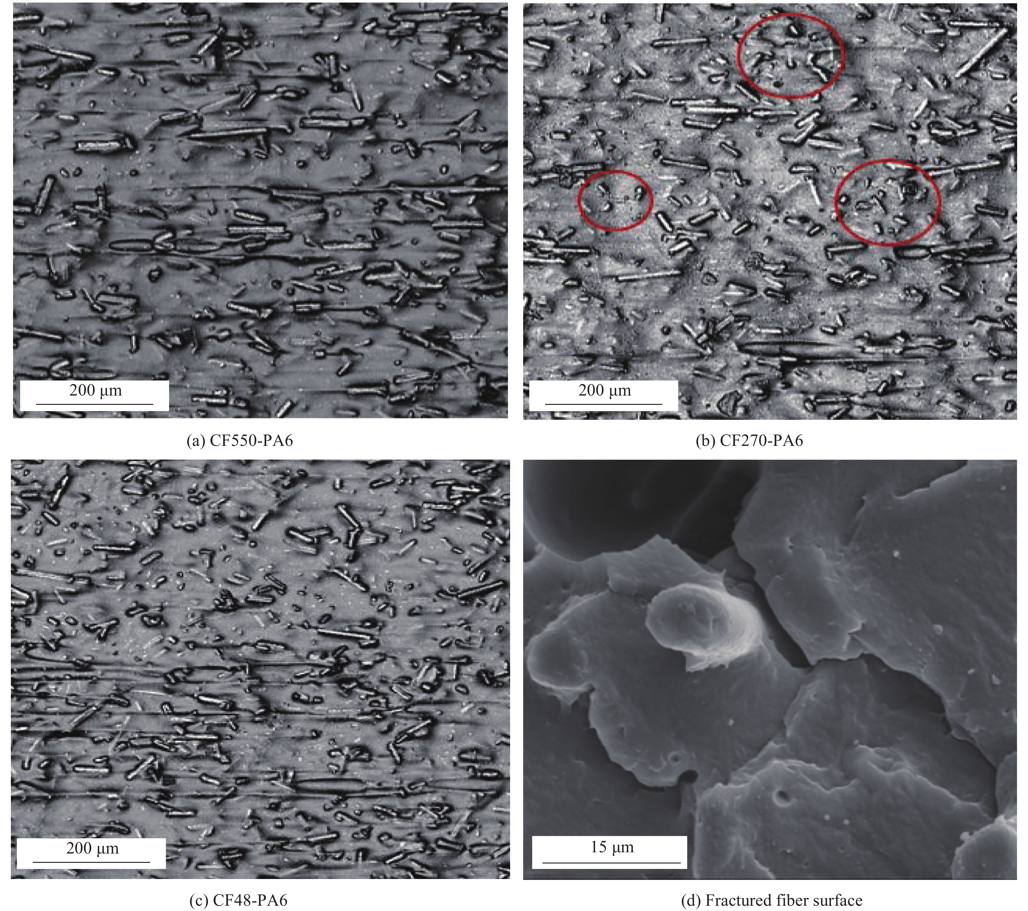
ratioCF550-PA6 PA6 WD-30 7 0.550 79 CF270-PA6 PA6 WD-50 7 0.270 39 CF48-PA6 PA6 WD-300 7 0.048 7 表 2 熔融沉积成型(FDM)工艺参数
Table 2 Fused deposition modeling (FDM) process parameters
Parameter Value Parameter Value Infill density 100% Layer height 0.2 mm Raster angle 0° Layer width 0.8 mm Nozzle temperature 300℃ Infill speed 20, 30, 40, 50,
60 mm/s表 3 CF270-PA6的DSC实验结果
Table 3 Differential scanning calorimetry (DSC) experimental results of CF270-PA6
Material Tg/℃ Tc/℃ Tm/℃ CF270-PA6 55 190 220 Notes:Tg—Glass transition temperature; Tc—Crystallization temperature; Tm—Melting temperature. 表 4 退火实验布置
Table 4 Annealing experiment setup
Set Material Annealing
temperature/℃Annealing
time/h1, 2, 3, 4, 5 CF270-PA6 70, 90, 120, 150, 200 7 Re CF270-PA6 No No Note:Re serves as the room temperature reference group without undergoing annealing treatment. -
[1] 黎宇航, 董齐, 邰清安, 等. 熔融沉积增材制造成形碳纤维复合材料的力学性能[J]. 塑性工程学报, 2017, 24(3): 225-230. DOI: 10.3969/j.issn.1007-2012.2017.03.037 LI Yuhang, DONG Qi, TAI Qing'an, et al. Mechanical properties of carbon fiber composite in fused deposition modeling of additive manufacturing[J]. Journal of Plasticity Engineering, 2017, 24(3): 225-230(in Chinese). DOI: 10.3969/j.issn.1007-2012.2017.03.037
[2] ZHANG W, COTTON C, SUN J, et al. Interfacial bonding strength of short carbon fiber/acrylonitrile-butadiene-styrene composites fabricated by fused deposition modeling[J]. Composites Part B: Engineering, 2018, 137: 51-59. DOI: 10.1016/j.compositesb.2017.11.018
[3] NING F, CONG W, QIU J, et al. Additive manufacturing of carbon fiber reinforced thermoplastic composites using fused deposition modeling[J]. Composites Part B: Engineering, 2015, 80: 369-378. DOI: 10.1016/j.compositesb.2015.06.013
[4] MAGRI A E, EL MABROUK K, VAUDREUIL S, et al. Mechanical properties of CF-reinforced PLA parts manufactured by fused deposition modeling[J]. Journal of Thermoplastic Composite Materials, 2019, 34(5): 581-595.
[5] IVEY M, MELENKA G W, CAREY J P, et al. Characterizing short-fiber-reinforced composites produced using additive manufacturing[J]. Advanced Manufacturing: Polymer & Composites Science, 2017, 3(3): 81-91.
[6] FERREIRA R T L, AMATTE I C, DUTRA T A, et al. Experimental characterization and micrography of 3D printed PLA and PLA reinforced with short carbon fibers[J]. Composites Part B: Engineering, 2017, 124: 88-100. DOI: 10.1016/j.compositesb.2017.05.013
[7] CHACON J M, CAMINERO M Á, NUNEZ P J, et al. Effect of nozzle diameter on mechanical and geometric performance of 3D printed carbon fibre-reinforced composites manufactured by fused filament fabrication[J]. Rapid Prototyping Journal, 2021, 27(4): 769-784. DOI: 10.1108/RPJ-10-2020-0250
[8] NARANJO J, AHUETT H, ORTA P, et al. Tensile properties and failure behavior of chopped and continuous carbon fiber composites produced by additive manufacturing[J]. Additive Manufacturing, 2019, 26: 227-241. DOI: 10.1016/j.addma.2018.12.020
[9] NING F, CONG W, HU Y, et al. Additive manufacturing of carbon fiber-reinforced plastic composites using fused deposition modeling: Effects of process parameters on tensile properties[J]. Journal of Composite Materials, 2017, 51(4): 451-462. DOI: 10.1177/0021998316646169
[10] PACE F, STAMOPOULOS A G, ECKL M, et al. Analysis of the manufacturing porosity in fused filament fabricated onyx/long fiber reinforced composites using X-ray computed tomography[J]. Journal of Nondestructive Evaluation, 2023, 42(4): 86.
[11] FERREIRA I, MELO C, NETO R, et al. Study of the annealing influence on the mechanical performance of PA12 and PA12 fibre reinforced FFF printed specimens[J]. Rapid Prototyping Journal, 2020, 26(10): 1761-1770. DOI: 10.1108/RPJ-10-2019-0278
[12] SUN B, MUBARAK S, ZHANG G, et al. Fused-deposition modeling 3D printing of short-cut carbon-fiber-reinforced PA6 composites for strengthening, toughening, and light weighting[J]. Polymers, 2023, 15(18): 3722. DOI: 10.3390/polym15183722
[13] LIAO G, LI Z, CHENG Y, et al. Properties of oriented carbon fiber/polyamide 12 composite parts fabricated by fused deposition modeling[J]. Materials & Design, 2018, 139: 283-292.
[14] SPOERK M, SAVANDAIAH C, ARBEITER F, et al. Anisotropic properties of oriented short carbon fibre filled polypropylene parts fabricated by extrusion-based additive manufacturing[J]. Composites Part A: Applied Science and Manufacturing, 2018, 113: 95-104. DOI: 10.1016/j.compositesa.2018.06.018
[15] PAPON E A, HAQUE A. Fracture toughness of additively manufactured carbon fiber reinforced composites[J]. Additive Manufacturing, 2019, 26: 41-52. DOI: 10.1016/j.addma.2018.12.010
[16] TEKINALP H L, KUNC V, VELEZ-GARCIA G M, et al. Highly oriented carbon fiber–polymer composites via additive manufacturing[J]. Composites Science and Technology, 2014, 105: 144-150.
[17] 管涛, 李元庆, 郭方亮, 等. 基于纤维取向分布图像处理技术的短纤维增强聚合物基复合材料力学性能预测方法[J]. 复合材料学报, 2024, 41(9): 4826-4836. GUAN Tao, LI Yuanqing, GUO Fangliang, et al. A method for predicting the mechanical properties of short fiber reinforced polymer composites based on fiber orientation distribution image processing technique[J]. Acta Materiae Compositae Sinica, 2024, 41(9): 4826-4836(in Chinese).
[18] YANG D, ZHANG H, WU J, et al. Fibre flow and void formation in 3D printing of short-fibre reinforced thermoplastic composites: An experimental benchmark exercise[J]. Additive Manufacturing, 2021, 37: 101686. DOI: 10.1016/j.addma.2020.101686
[19] YAN J, DEMIRCI E, GANESAN A, et al. Extrusion width critically affects fibre orientation in short fibre reinforced material extrusion additive manufacturing[J]. Additive Manufacturing, 2022, 49: 102496. DOI: 10.1016/j.addma.2021.102496
[20] American Society of Testing Materials. Standard test method for tensile properties of plastics: ASTM D638[S]. West Conshohocken, PA: ASTM International, 2014.
[21] HELLER B P, SMITH D E, JACK D A. Effects of extrudate swell and nozzle geometry on fiber orientation in fused filament fabrication nozzle flow[J]. Additive Manufacturing, 2016, 12: 252-264. DOI: 10.1016/j.addma.2016.06.005
[22] HELLER B P, SMITH D E, JACK D A. Planar deposition flow modeling of fiber filled composites in large area additive manufacturing[J]. Additive Manufacturing, 2019, 25: 227-238. DOI: 10.1016/j.addma.2018.10.031
[23] GENG P, ZHAO J, WU W, et al. Effects of extrusion speed and printing speed on the 3D printing stability of extruded PEEK filament[J]. Journal of Manufacturing Processes, 2019, 37: 266-273. DOI: 10.1016/j.jmapro.2018.11.023
[24] 熊爱华, 柳和生, 黄兴元, 等. 纤维参数对纤维取向及塑件变形影响模拟研究[J]. 材料科学与工艺, 2012, 20(3): 132-138. DOI: 10.11951/j.issn.1005-0299.20120326 XIONG Aihua, LIU Hesheng, HUANG Xingyuan, et al. Simulated study on effect of fiber parameters on fiber orientation and injection-molded part's deflection[J]. Materials Science & Technology, 2012, 20(3): 132-138(in Chinese). DOI: 10.11951/j.issn.1005-0299.20120326
[25] EL MAGRI A, EL MABROUK K, VAUDREUIL S, et al. Optimization of printing parameters for improvement of mechanical and thermal performances of 3D printed poly(ether ether ketone) parts[J]. Journal of Applied Polymer Science, 2020, 137(37): 49087. DOI: 10.1002/app.49087
[26] WANG X, XU D, LIU H, et al. Effects of thermal residual stress on interfacial properties of polyphenylene sulphide/carbon fibre (PPS/CF) composite by microbond test[J]. Journal of Materials Science, 2016, 51: 334-343. DOI: 10.1007/s10853-015-9251-2
[27] YAN X, IMAI Y, SHIMAMOTO D, et al. Relationship study between crystal structure and thermal/mechanical properties of polyamide 6 reinforced and unreinforced by carbon fiber from macro and local view[J]. Polymer, 2014, 55(23): 6186-6194. DOI: 10.1016/j.polymer.2014.09.052
[28] LIU B, WANG X, LONG S, et al. Interfacial micromechanics of carbon fiber-reinforced polyphenylene sulfide composites[J]. Composite Interfaces, 2014, 21(4): 359-369. DOI: 10.1080/15685543.2014.878875
[29] LI H, WANG Y, ZHANG C, et al. Effects of thermal histories on interfacial properties of carbon fiber/polyamide 6 composites: Thickness, modulus, adhesion and shear strength[J]. Composites Part A: Applied Science and Manufacturing, 2016, 85: 31-39. DOI: 10.1016/j.compositesa.2016.03.007
[30] 孙春燕, 畅同晨, 闫盼盼, 等. 残余应力对碳纤维填充聚合物注塑制品电阻率的影响[J]. 机械工程学报, 2014, 50(6): 81-86. DOI: 10.3901/JME.2014.06.081 SUN Chunyan, CHANG Tongchen, YAN Panpan, et al. The influence of residual stress on the electrical resistivity of carbon fiber reinforced polymer injection molded products[J]. Journal of Mechanical Engineering, 2014, 50(6): 81-86(in Chinese). DOI: 10.3901/JME.2014.06.081
[31] BHANDARI S, LOPEZ-ANIDO R A, GARDNER D J. Enhancing the interlayer tensile strength of 3D printed short carbon fiber reinforced PETG and PLA composites via annealing[J]. Additive Manufacturing, 2019, 30: 100922. DOI: 10.1016/j.addma.2019.100922
-
其他相关附件
-
目的
针对熔融沉积成型和退火热处理工艺中,不同工艺参数下制件的力学性能不同问题。本文通过对平面纤维取向角进行统计,探索不同工艺参数下制件的纤维取向分布情况以及其在拉伸模量上的变化。
方法通过对平面纤维取向角统计,得到不同工艺参数下短切碳纤维增强尼龙6制件的平面纤维取向分布直方图及其正态拟合曲线。首先,为保证进行显微观察和拉伸实验样件的处理工艺相同,在不同工艺参数下同时制出用于拉伸试验的哑铃型试样和用于显微观察的单层-单丝试样。其次,在DNS-10电子万能试验机上测试不同工艺参数下制件的拉伸模量;利用OLS4100 3D测量激光显微镜在单层-单丝试样顶面进行显微图像拍摄;并导入Image J软件中,每张图像x选取50根较长纤维测量平面纤维取向角。最后,根据测量的平面纤维取向角数据绘制频率分布直方图,并对其进行正态拟合以便进行对比分析。
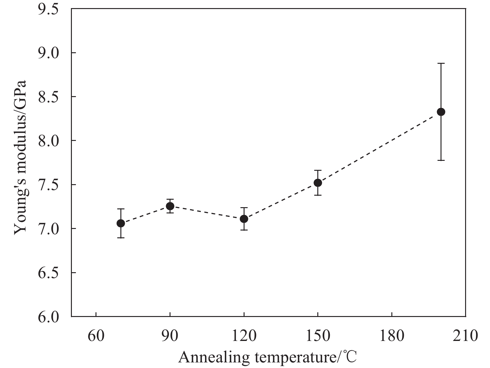
结果从微观纤维取向分布和宏观拉伸模量的结果中,可以得到:①增材工艺方面,随着打印速度的增加,取向与打印方向保持一致的纤维数量呈先上升后下降的趋势,在V=40 mm/s时获得峰值,标准差σ为11.14,频率峰值为0.42;同时,发现拉伸模量亦呈现先上升后下降变化规律,并在V=40 mm/s处获得因素内最大的杨氏模量值7.22 GPa,对两者进行Pearson相关性系数计算,发现两者呈强相关。②碳纤维长径比方面,在丝材中加入不同长径比的碳纤维分别进行制件、测量和表征,经统计发现纤维取向一致性并非随着加入碳纤维长径比的增大而提高,这与以往发现的纤维长径比在25~100范围内,平均纤维取向随着纤维长径比增大而增大有所差异,观察显微图像发现其与制件中的保留长径比相关。③退火温度方面,不同退火温度下对制件的纤维取向皆产生了积极影响,而当退火温度介于玻璃转化温度和结晶温度之间时,此种积极影响最为显著,并在150℃下获得标准差为6.39、频率峰值为0.54的最优效果。宏观拉伸模量方面,当退火温度接近玻璃转化温度时,拉伸模量取最小值;退火温度介于玻璃转化温度和结晶温度之间时,呈先下降后上升趋势,在150℃时获得局部最大拉伸模量7.52GPa;当退火温度略高于结晶温度时,获得因素内最大的拉伸模量8.33GPa。
结论增材工艺方面,发现不同打印速度不仅会对微观纤维取向产生影响,而且其纤维取向与拉伸模量之间呈强相关,这说明增材工艺参数对拉伸模量的影响与纤维取向的变化密切相关。此外,碳纤维长径比和退火温度的变化皆会对微观纤维取向产生不同影响。因此,本文采用的平面纤维取向角统计方法,能够实现不同工艺参数下制件微观纤维取向的表征,为工艺参数优化提供参考。
-
短切纤维增强复合材料制件的增材制造及其热处理中,由于其采用的工艺参数不同,会得到不同的制件力学性能,这对其广泛应用产生了一定的限制。目前,主要通过对微观孔隙率、层间结合状态分析,实现工艺参数优化。而纤维取向作为决定制件刚度的关键因素,尚未得到足够的研究,尤其是纤维取向的定量分析。
本文通过在单层-单丝试样的顶面进行显微观察,使用Image J软件测量平面纤维取向角,得到不同工艺参数下的平面纤维取向分布直方图,探究了不同碳纤维长径比、打印速度和退火温度对于纤维取向的影响。随着打印速度的增加,发现纤维取向与打印方向的一致性呈先上升后下降变化趋势,并在40 mm/s时取得最优,标准差为11.14,频率峰值为0.42;同时,拉伸模量也呈现此变化趋势,通过Pearson相关系数计算,两者呈强相关性,增材工艺参数对拉伸模量的影响与纤维取向的变化密切相关。纤维一致性并非随着加入碳纤维长径比的增大而提高,而是与制件中的保留纤维长径比相关。在不同退火温度下,发现当退火温度介于玻璃转化温度和结晶温度之间时对纤维取向的影响显著,并在150℃时获得标准差为6.39、频率峰值为0.54的最优取向。
不同打印速度下的显微图像和平面纤维取向分布(a)V从20到60的显微图像;(b)v=20;(c)v=30;(d)v=40;(e)v=50;(f)v=60





 下载:
下载:


