


Comparative study on the machining quality of thin-walled CFRP circular cell in end face grinding and milling
-
摘要: 阵列复材管是由薄壁碳纤维增强树脂基复合材料(CFRP)管在水平面内二维密排形成的蜂窝结构材料,可应用于航空航天等领域。为探索端面磨削和铣削阵列复材管的可行性,以CFRP管元胞为研究对象,考虑其薄壁特征引入切出角度为实验参数,并开展端面加工实验研究切出角度、刀具实际进给率、轴向切削深度和切削速度对已加工表面形貌和力的影响。结果表明:切出角度通过影响加工区域的材料支撑状态和纤维切削角影响损伤的类型及形成过程,过大或过小的切出角度均可能产生加工损伤;通过降低刀具实际进给率、轴向切削深度或提升切削速度均可一定程度上降低切削力并抑制端面磨削时小切出角度条件下的损伤,但上述措施无法抑制端面铣削损伤。端面磨削相比于端面铣削具有更大的高效低损伤加工工艺操作区间,建议优先选用。Abstract: Carbon fiber reinforced resin composite (CFRP) circular cell honeycomb is with honeycomb structure formed by 2D dense arrangement of thin-walled circular cells in a horizontal plane, which can be applied in the aerospace. In order to explore the feasibility of end face grinding and milling on CFRP circular cell honeycomb, CFRP circular cell was identified as the experimental subject and exit angle was introduced considering the thin-walled characteristic of the cell in this research. End face machining experiments were conducted to study the effects of exit angle, material removal rate, axial cutting depth, and cutting speed on the machined surface morphology and force. The results indicate that the exit angle affects the material support state of the processing area and the fiber cutting angle to influence the formation of damage and excessive or insufficient exit angles may cause damage. By reducing the real feed rate, axial cutting depth or increasing the cutting speed may reduce cutting force and restrain the damage under the condition of small exit angle in end face grinding to some extent, but the above measures cannot have an impact on milling damage. End face grinding is preferred because of its larger efficiency and low-damage machining process operation range.
-
Key words:
- CFRP /
- honeycomb /
- milling /
- grinding /
- machining damage /
- cutting force
-

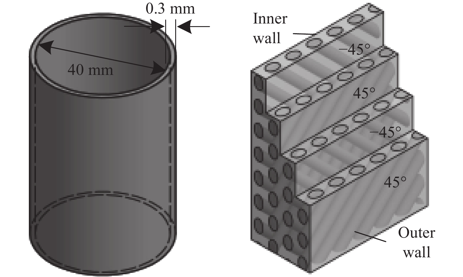
图 1 碳纤维增强树脂基复合材料(CFRP)管结构示意图
Figure 1. Schematic diagram of carbon fiber reinforced resin composite (CFRP) circular cell
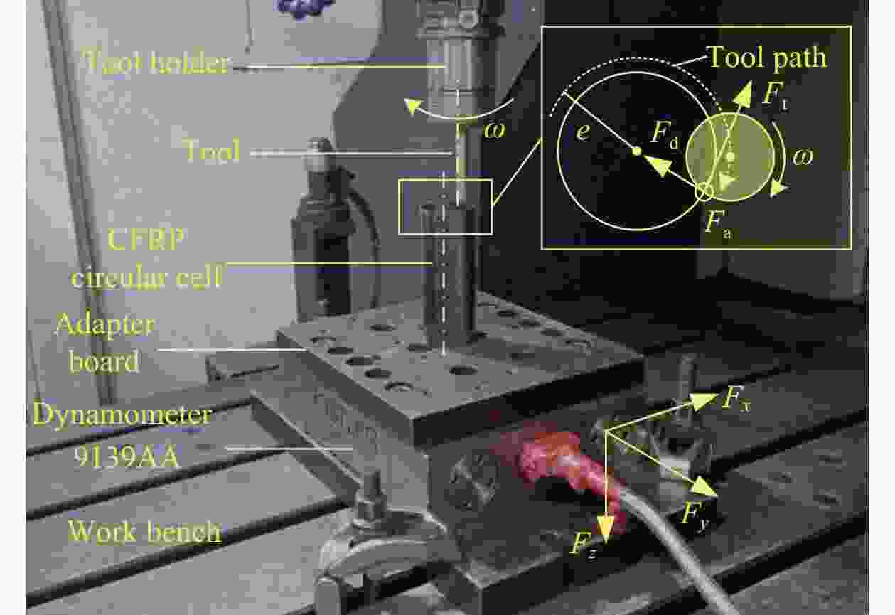
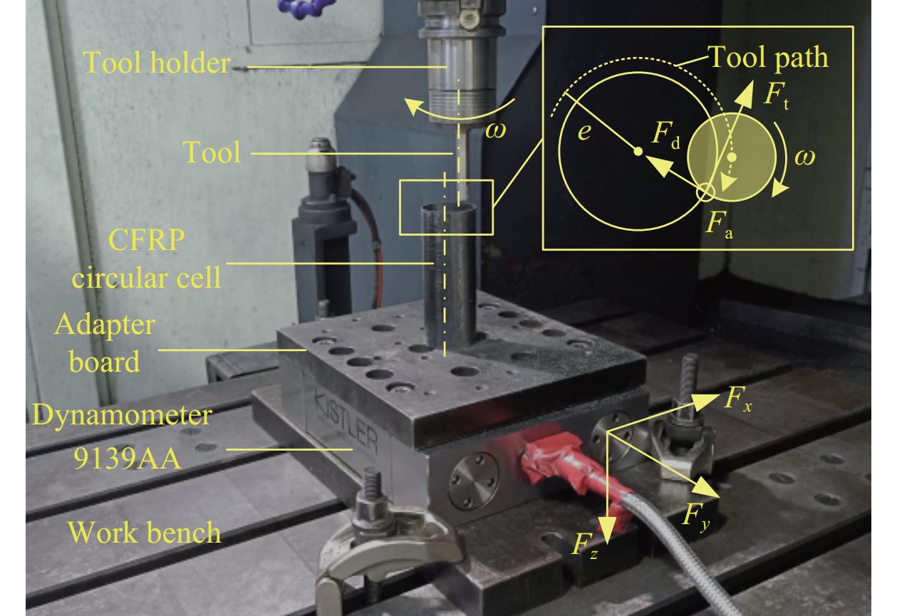
图 3 端面加工实验设置
ω—Direction of tool rotation; e—Distance between axes of CFRP circular cell and tools; Fd, Ft, Fa—Radial force, tangential force and axial force respectively; Fx, Fy, Fz—Forces measured by dynamometer
Figure 3. Experimental setup for end face machining

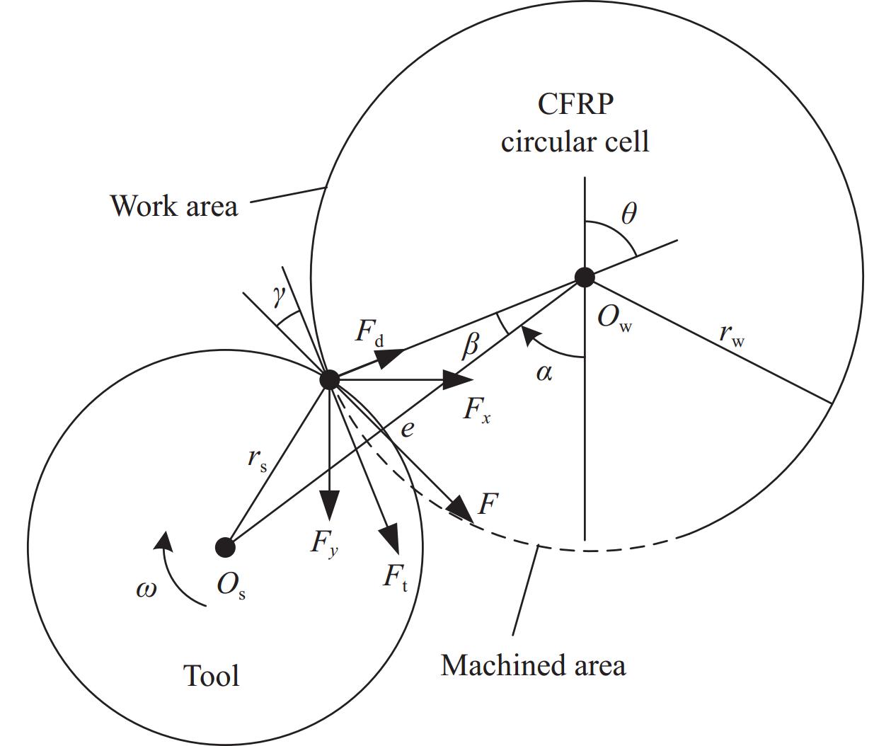
图 4 CFRP管切削力分解示意图
Figure 4. Schematic diagram of cutting force decomposition of CFRP circular cell
α—Phase of tool movement during circular interpolation, when the tool is directly below the workpiece, the phase is 0;β—Angle formed by the line formed by cutting point and axis of CFRP circular cell and line formed by axes of tools and CFRP circular cell; θ—Angle between coordinate systems of dynamometer and workpiece; γ—Angle between the direction of the combined force in the horizontal plane and the wall of the CFRP circular cell; Os—Axis of the tool; rs—Radius of the tool; Ow—Axis of CFRP circular cell; rw—Radius of CFRP circular cell; F—Resultant in horizontal plane

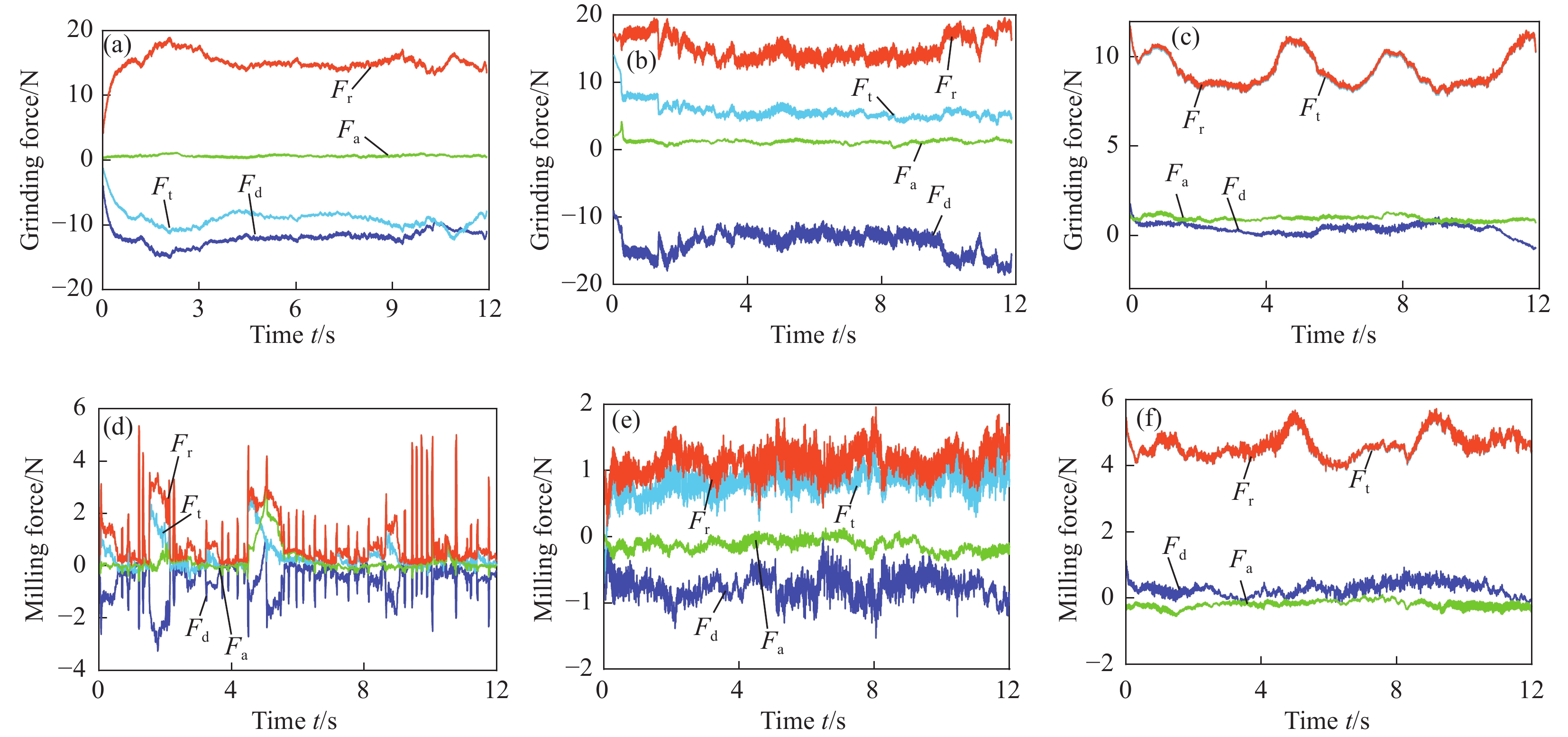
图 5 CFRP管磨削力及铣削力变化:(a)磨削,切削角φ=40°;(b)磨削,φ=80°;(c)磨削,φ=140°;(d)铣削,φ=40°;(e)铣削,φ=80°;(f)铣削,φ=140°
Fr—Three-way resultant
Figure 5. Variation of grinding force and milling force of CFRP circular cell: (a) Grinding, exit angle φ=40°; (b) Grinding, φ=80°; (c) Grinding, φ=140°;(d) Milling, φ=40°; (e) Milling, φ=80°; (f) Milling, φ=140°
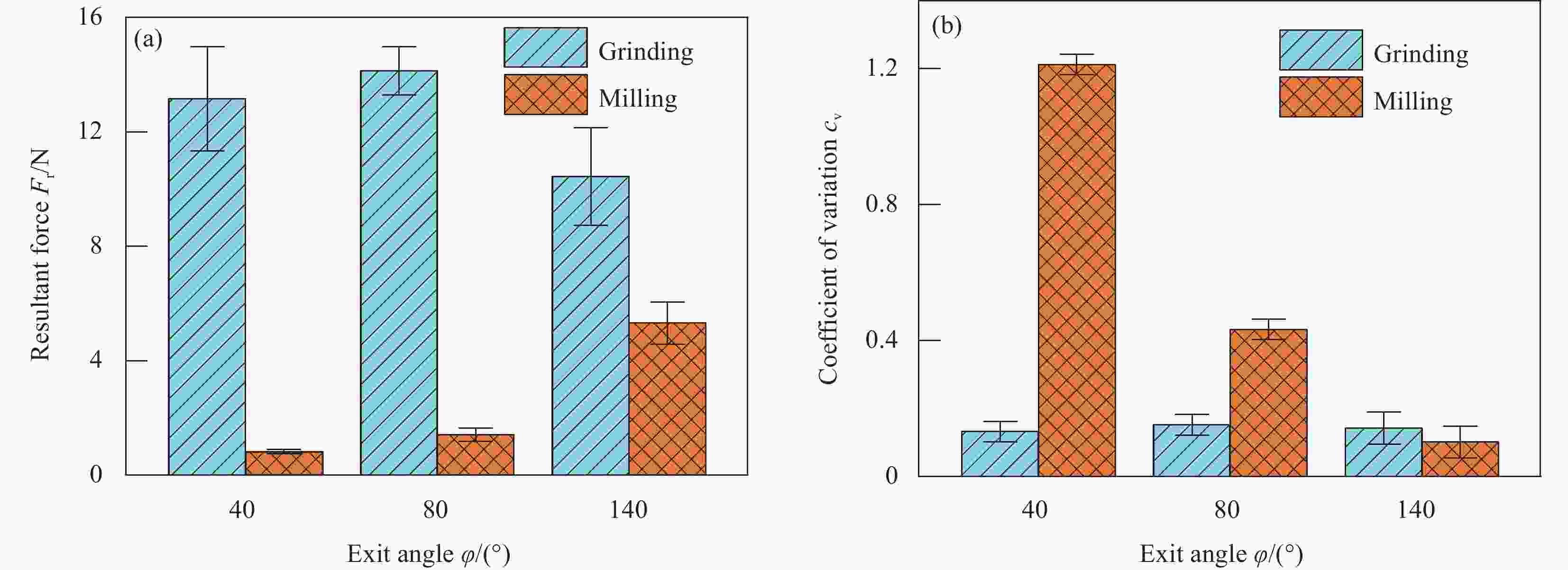
图 6 CFRP管磨削力与铣削力对比:(a)力的数值;(b)力的变异系数
Figure 6. Comparison of grinding force and milling force of CFRP circular cell: (a) Magnitude of force; (b) Coefficient of variation of force
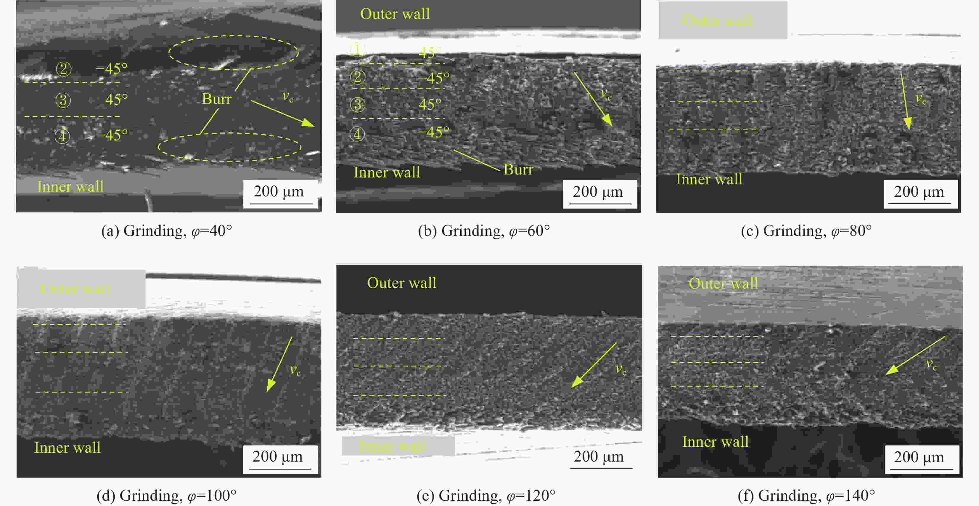
图 7 切出角度对CFRP管端面磨削形貌影响
Figure 7. Effect of exit angle on the grinding morphology of CFRP circular cell

图 8 φ=40°时CFRP管端面磨削已加工表面形貌
Figure 8. Topography of machined surface of end face grinding of CFRP circular cell at φ=40°

图 9 CFRP管磨削力及磨削作用角随切出角度变化:(a)切出角度对磨削力影响;(b)切出角度对磨削作用角影响
Figure 9. Effect of exit angle on grinding force and interaction angle of grinding of CFRP circular cell: (a) Effect of exit angle on grinding force; (b) Effect of exit angle on the interaction angle of grinding

图 10 切出角度对CFRP管加工区域材料支撑的影响:(a)切出角度较小,外壁材料支撑较弱;(b)切出角度较大,外壁材料支撑增强
Figure 10. Effect of exit angle on material support in the machined area of CFRP circular cell: (a) Smaller exit angle and weaker support of outer wall material; (b) Relatively large exit angle and reinforced support of outer wall material

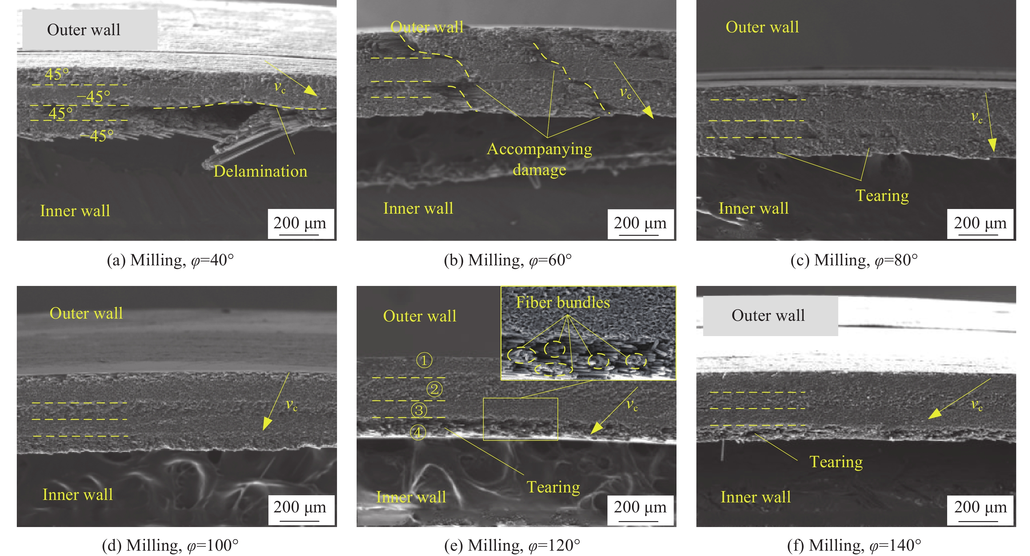
图 11 切出角度对CFRP管端面铣削形貌影响
Figure 11. Effect of exit angle on milling topography of CFRP circular cell

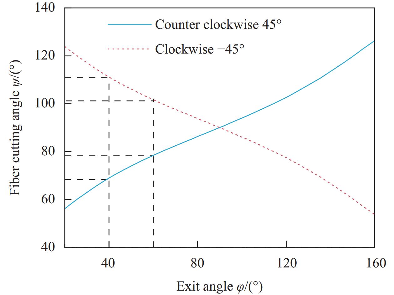
图 12 切出角度对CFRP管纤维切削角的影响
Figure 12. Effect of exit angle on the fiber cutting angle of CFRP circular cell

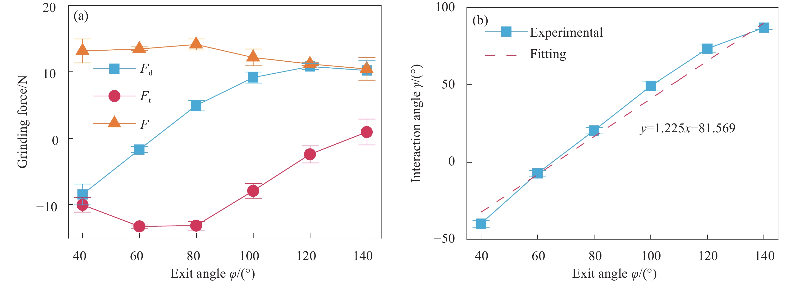
图 13 CFRP管端面铣削力随切出角度变化:(a)切出角度对铣削力影响;(b)切出角度对铣削作用角影响
Figure 13. Effect of exit angle on milling force and interaction angle of milling of CFRP circular cell: (a) Effect of exit angle on milling force; (b) Effect of exit angle on interaction angle of milling
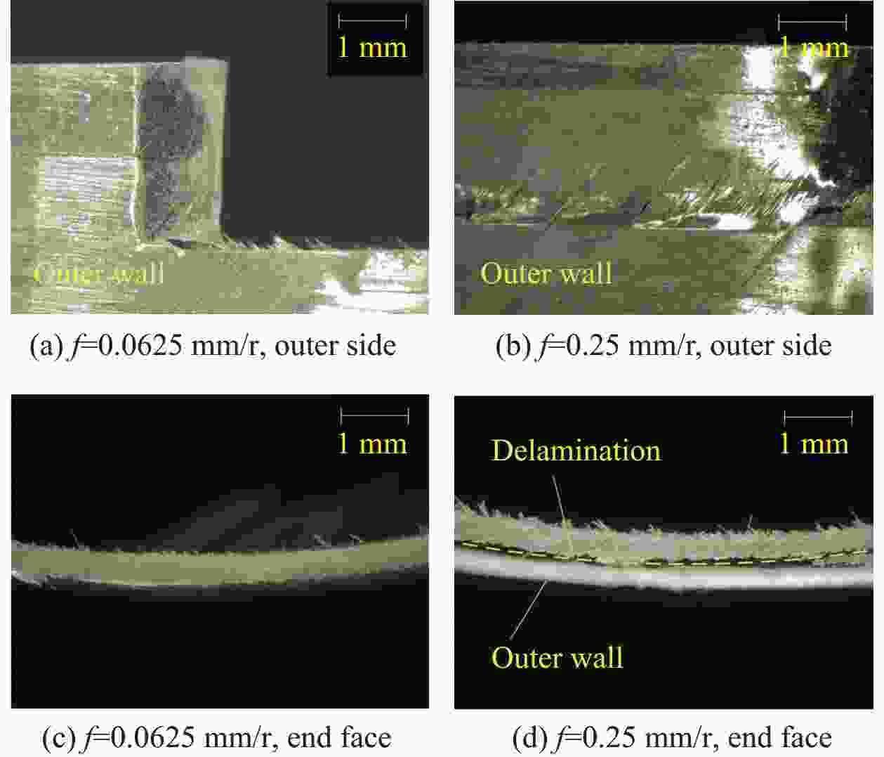
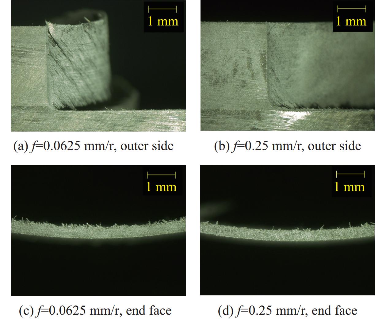
图 14 CFRP管端面磨削φ=40°时进给率f对表面形貌影响
Figure 14. Effect of feed rate f on surface topography when grinding CFRPcircular cell at φ=40°
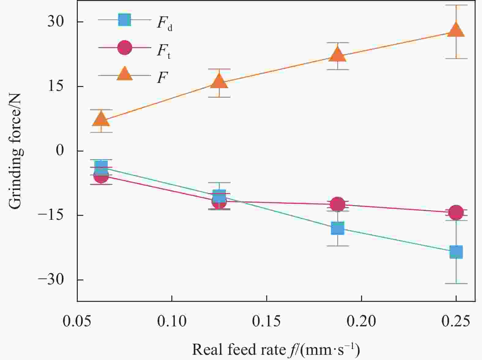
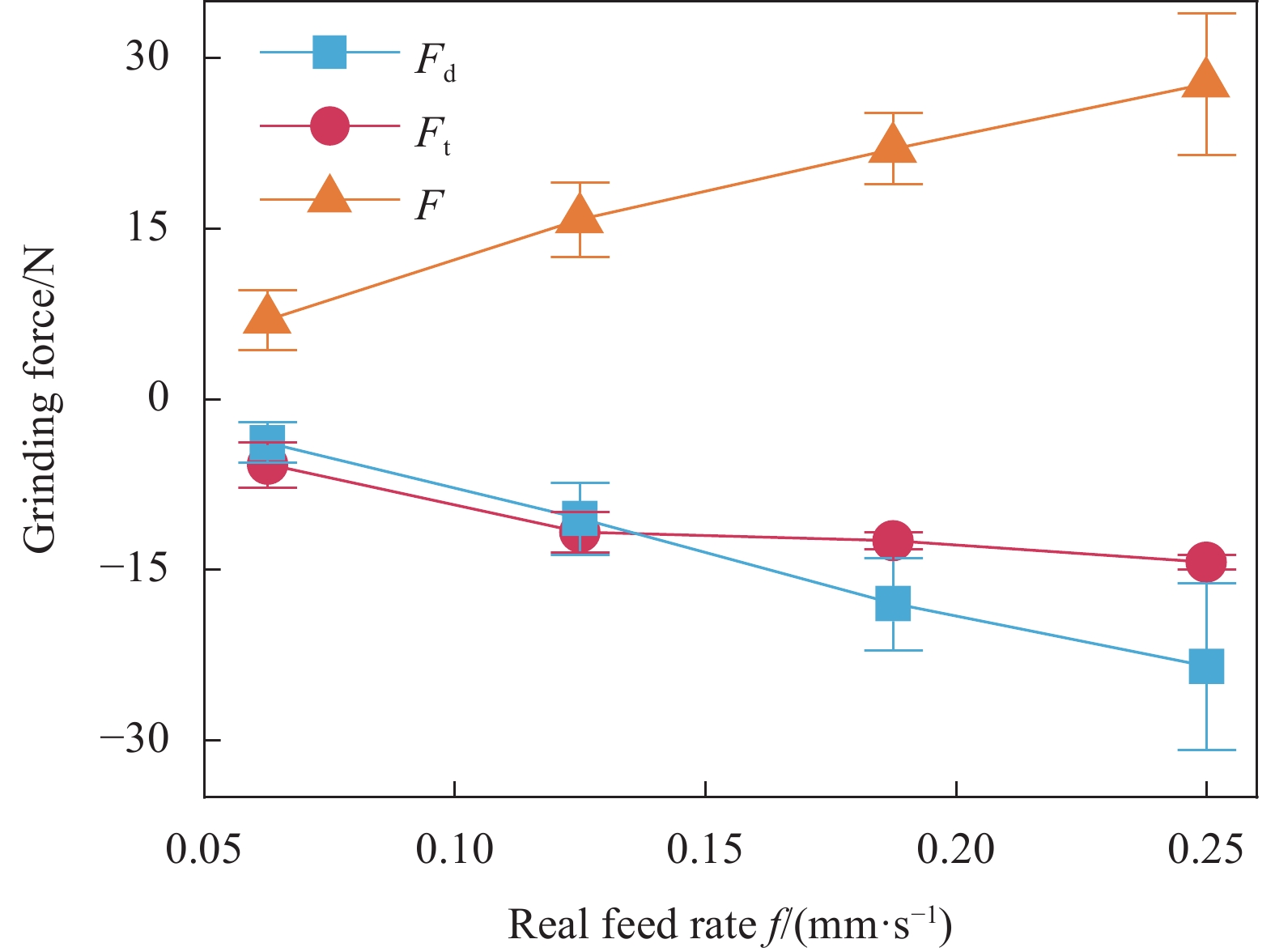
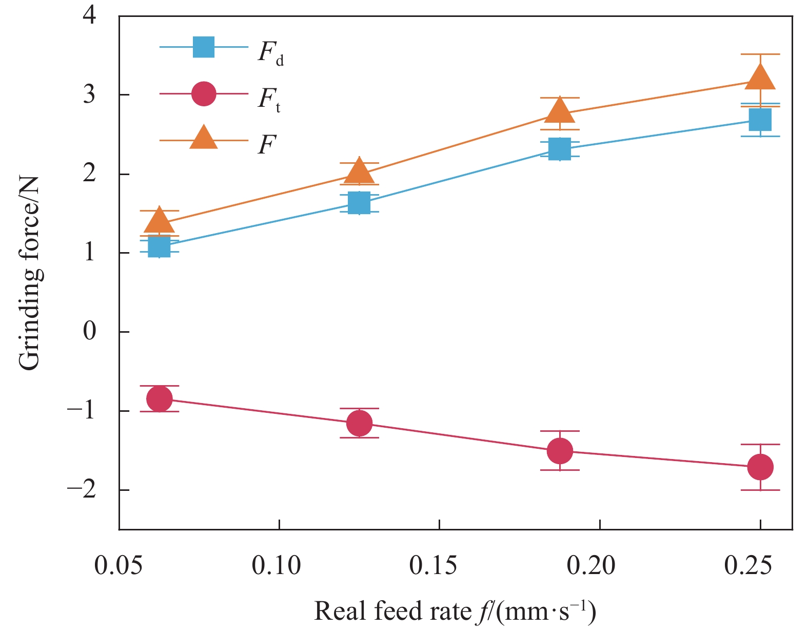
图 15 CFRP管端面磨削φ=40°时f对磨削力影响
Figure 15. Effect of f on grinding force when grinding CFRP circular cell at φ=40°

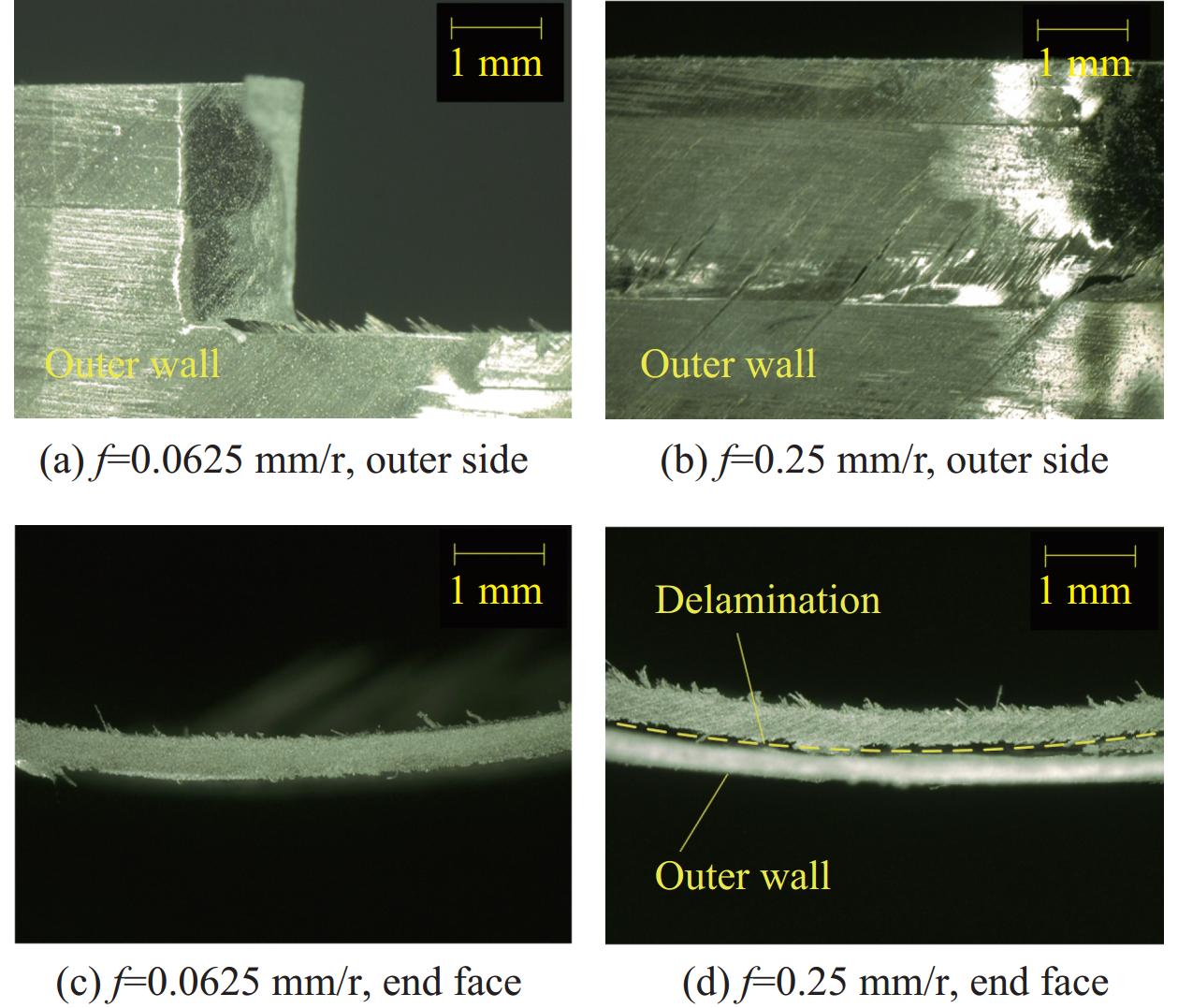
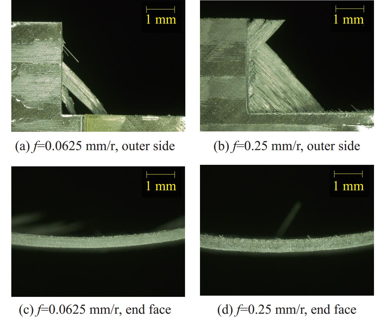
图 16 CFRP管端面铣削φ=40°时f对形貌影响
Figure 16. Effect of f on surface morphology when milling CFRP circular cell at φ=40°

图 17 CFRP管端面铣削φ=40°时f对铣削力影响
Figure 17. Effect of f on milling force when milling CFRP circular cell at φ=40°
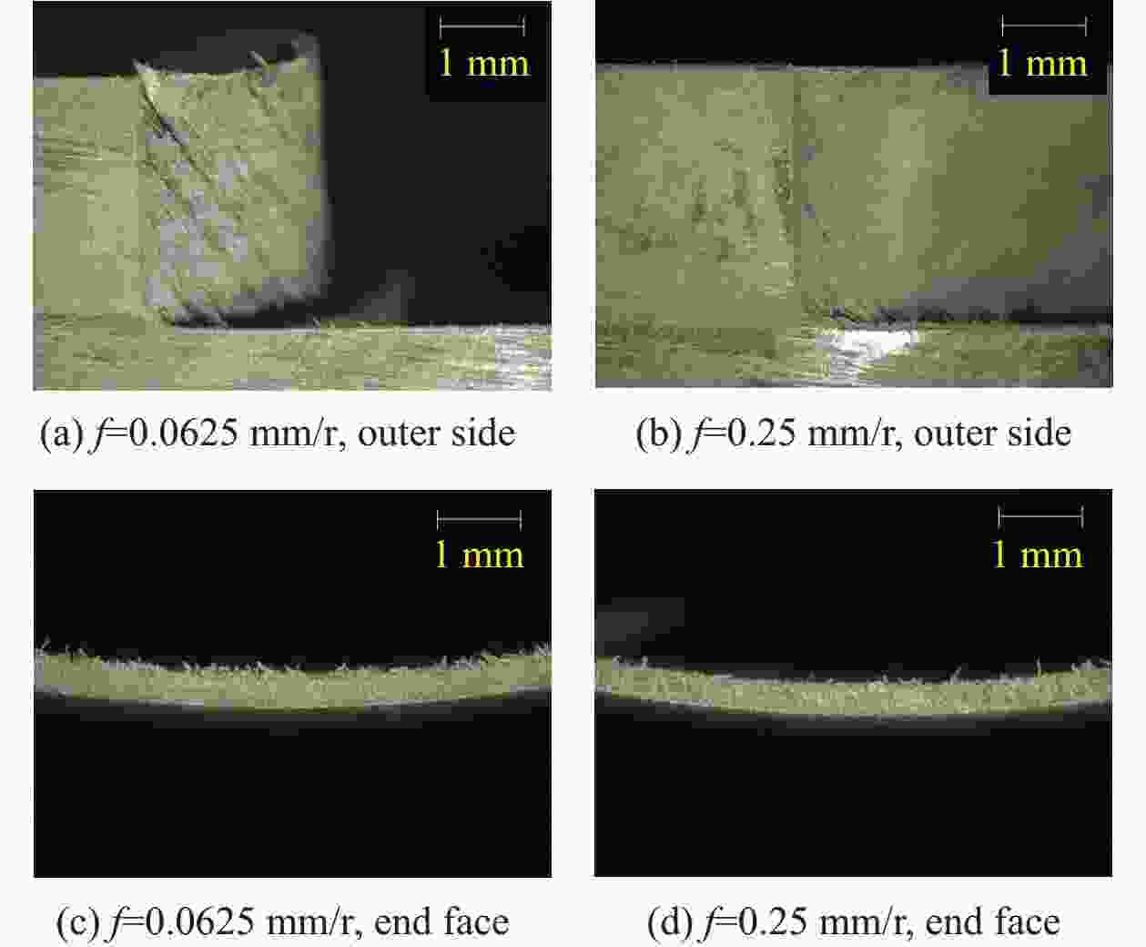
图 18 CFRP管端面磨削φ=100°时f对形貌影响
Figure 18. Effect of f on surface morphology when grinding CFRP circular cell at φ=100°
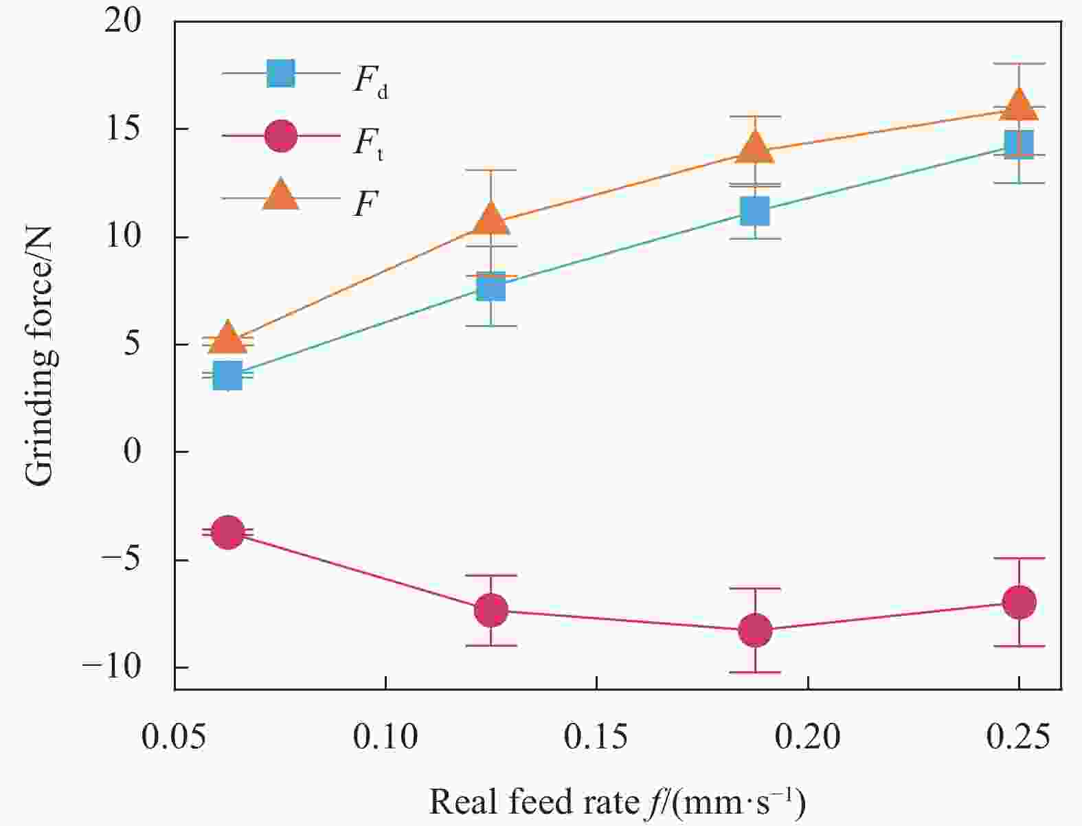
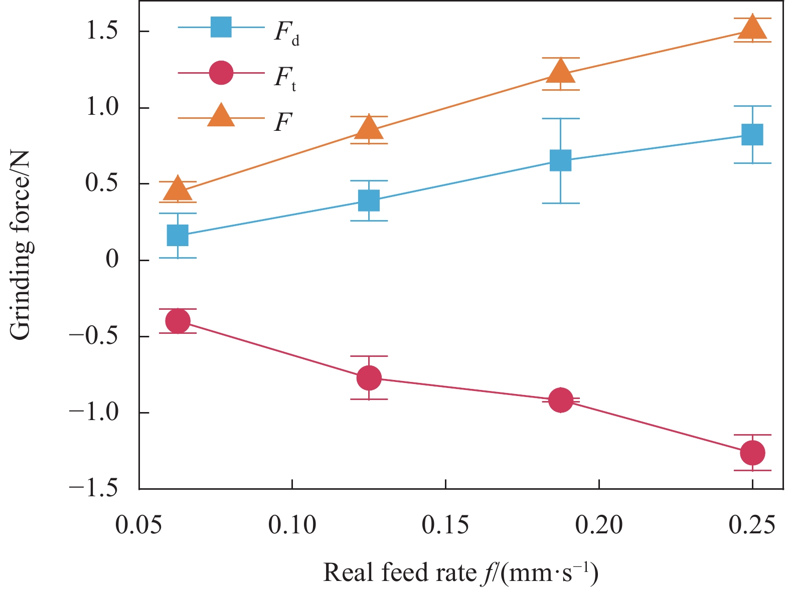
图 19 CFRP管端面磨削φ=100°时f对磨削力影响
Figure 19. Effect of f on grinding force when grinding CFRP circular cell at φ=100°

图 20 CFRP管端面铣削φ=100°时f对形貌影响
Figure 20. Effect of f on surface morphology when milling CFRP circular cell at φ=100°

图 21 CFRP管端面铣削φ=100°时f对铣削力影响
Figure 21. Effect of f on milling force when milling CFRP circular cell at φ=100°

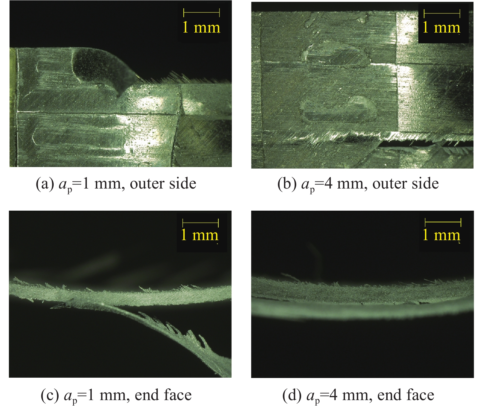
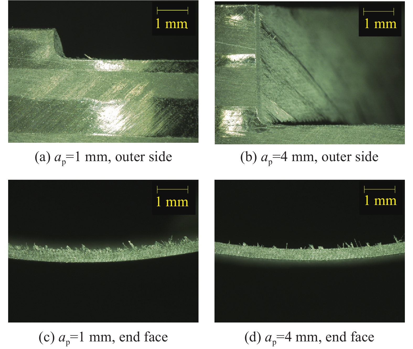
图 22 CFRP管端面磨削φ=40°时轴向深度ap对形貌影响
Figure 22. Effect of axial cutting depth ap on surface morphology when grinding CFRP circular cell at φ=40°

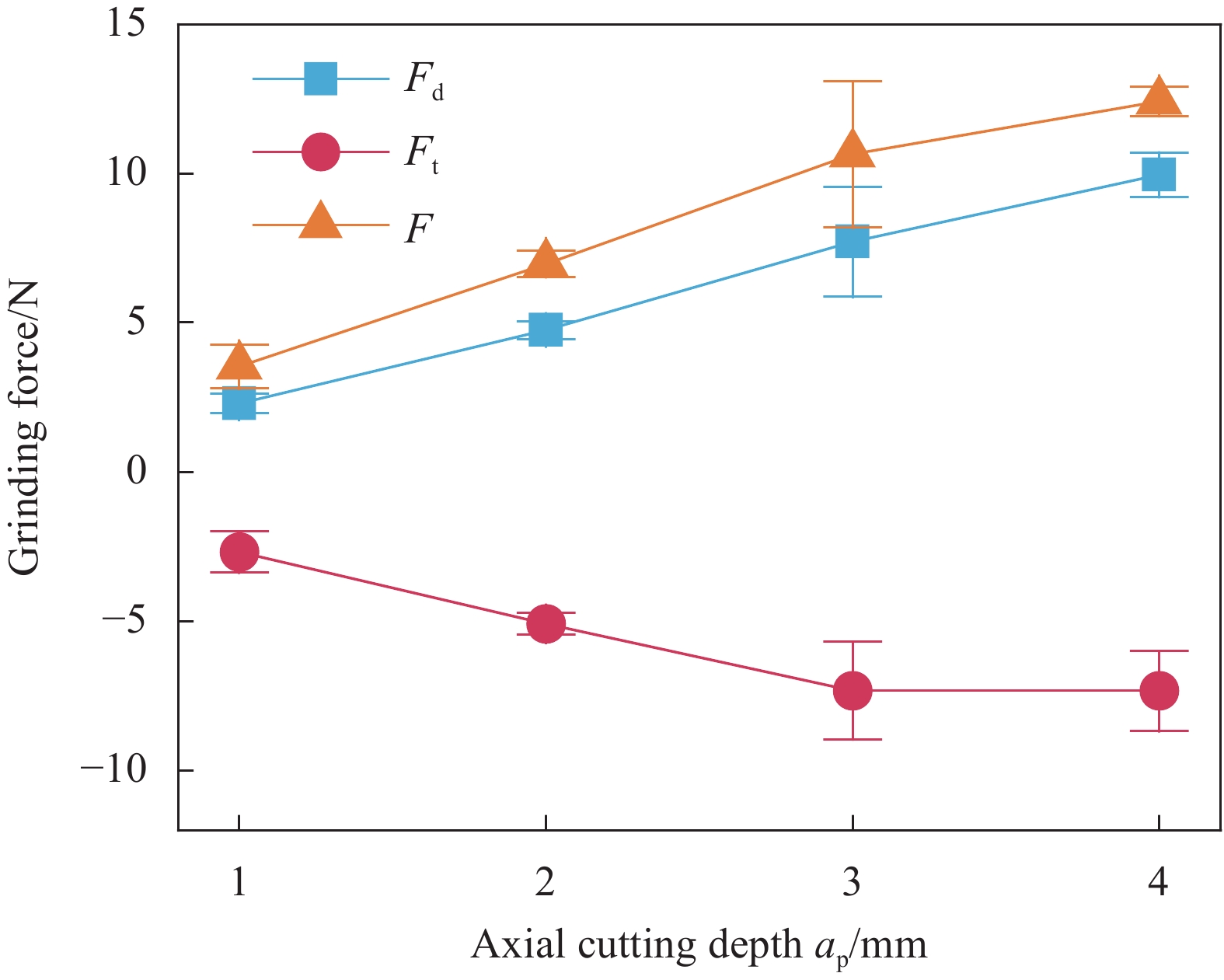
图 23 CFRP管端面磨削φ=40°时ap对力影响
Figure 23. Effect of ap on grinding force when grinding CFRP circular cell at φ=40°
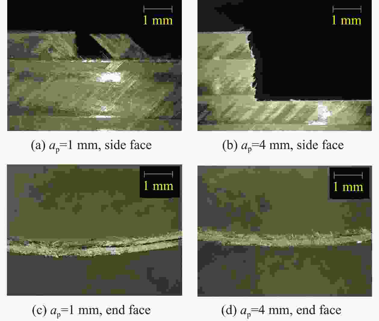
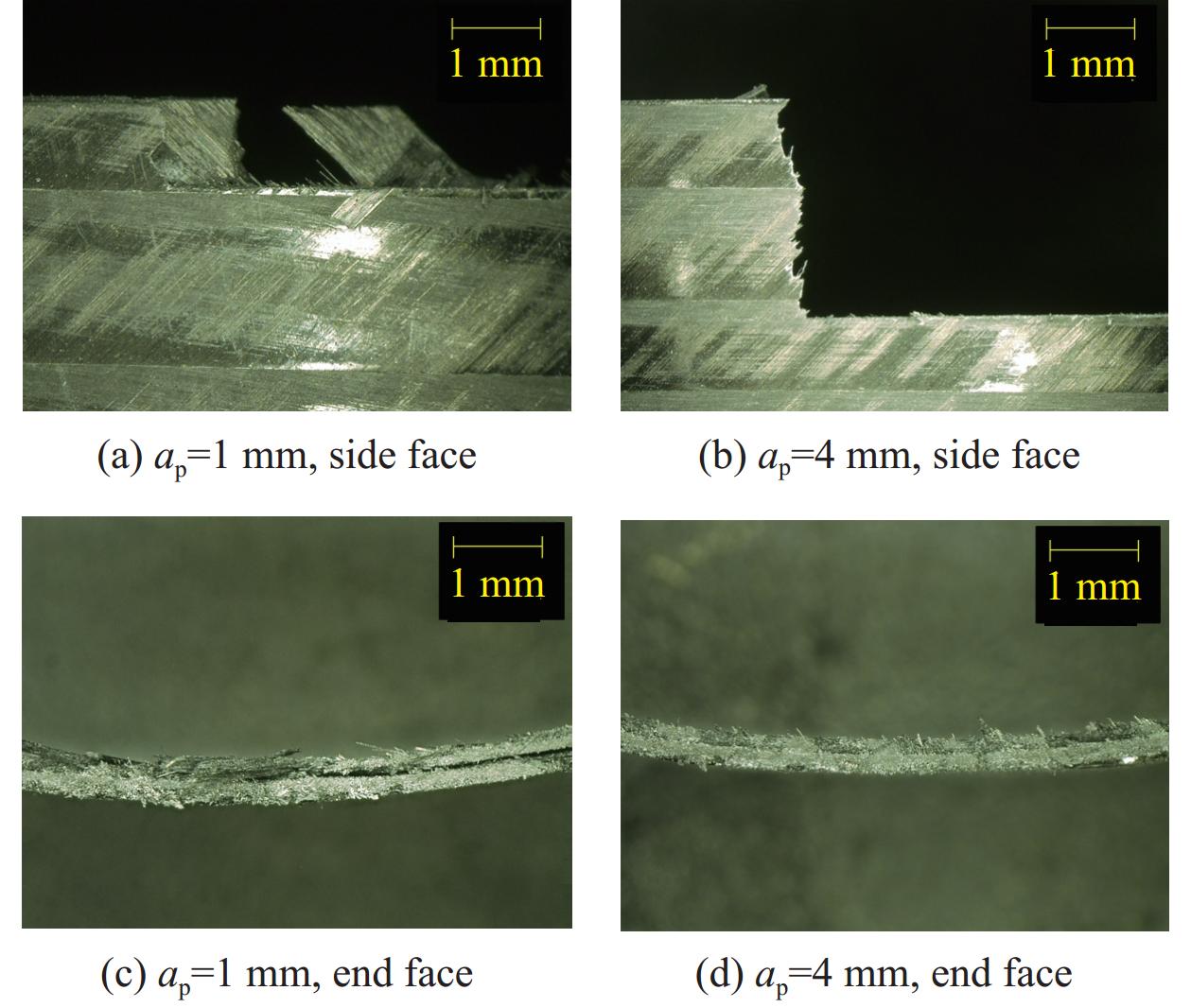
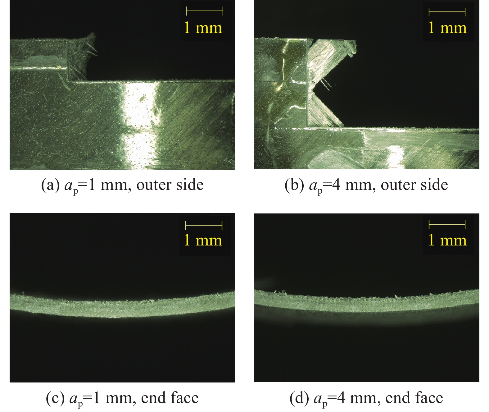
图 24 CFRP管端面铣削φ=40°时ap对形貌影响
Figure 24. Effect of ap on surface morphology when milling CFRP circular cell at φ=40°

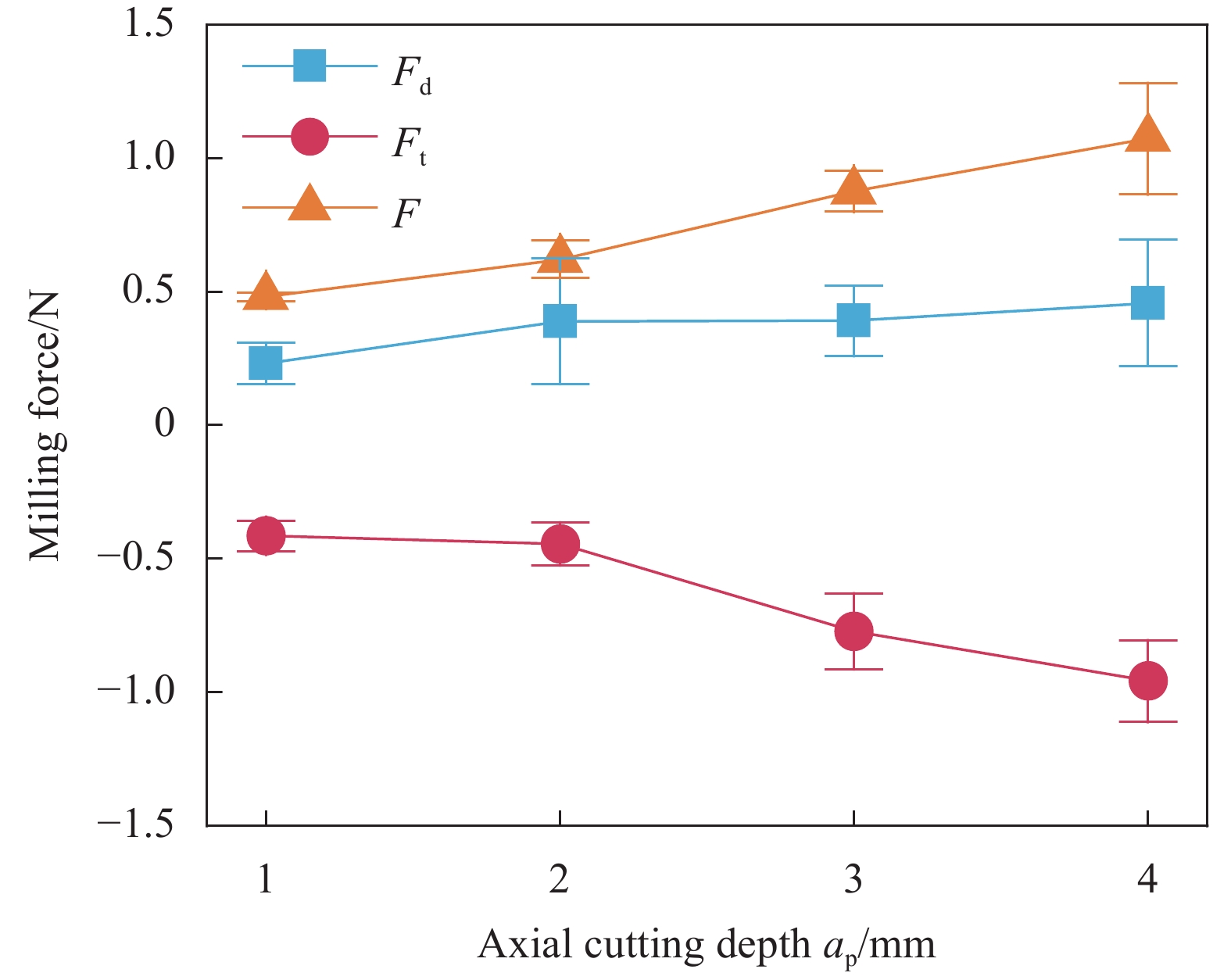
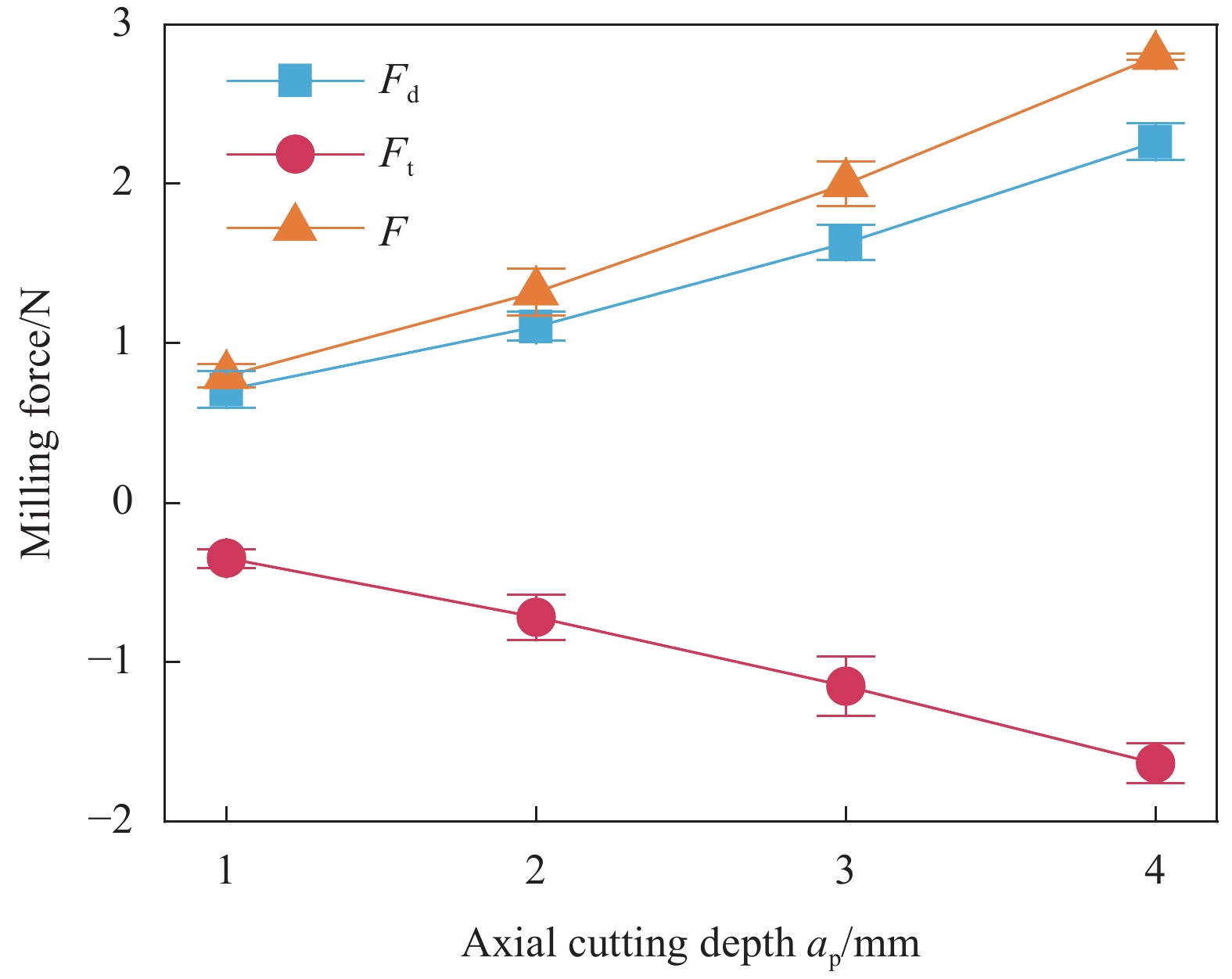
图 25 CFRP管端面铣削φ=40°时ap对力影响
Figure 25. Effect of ap on milling force when milling CFRP circular cell at φ=40°
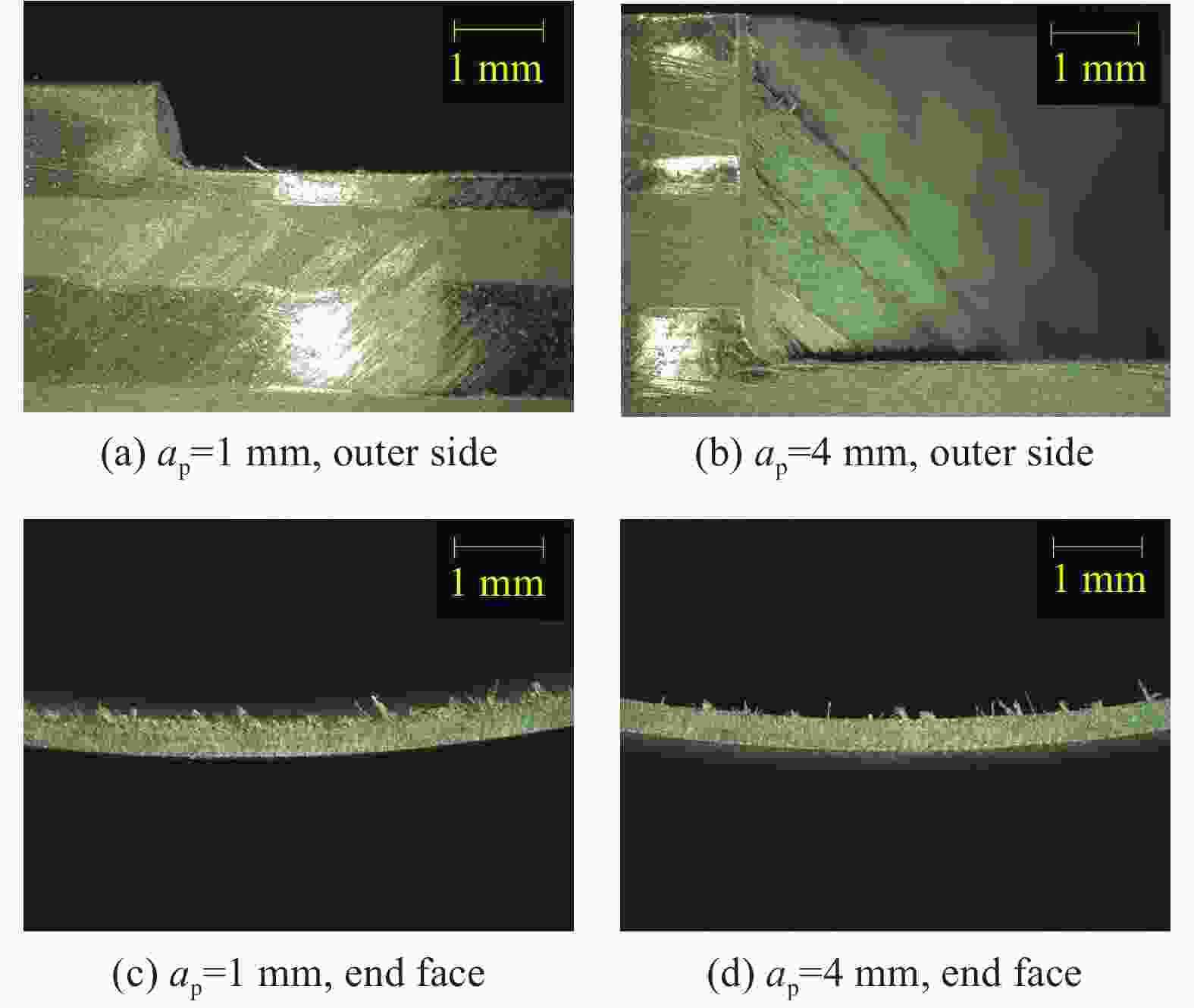
图 26 CFRP管端面磨削φ=100°时ap对形貌影响
Figure 26. Effect of ap on surface morphology when grinding CFRP circular cell at φ=100°

图 27 CFRP管端面磨削φ=100°时ap对力影响
Figure 27. Effect of ap on grinding force when grinding CFRP circular cell at φ=100°
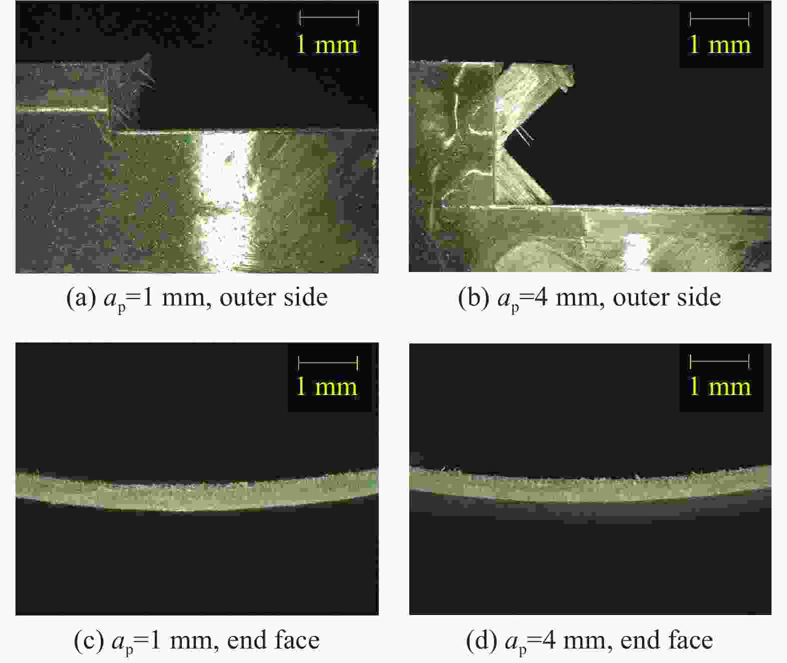
图 28 CFRP管端面铣削φ=100°时ap对形貌影响
Figure 28. Effect of ap on surface morphology when milling CFRP circular cell at φ=100°

图 29 CFRP管端面铣削φ=100°时ap对力影响
Figure 29. Effect of ap on milling force when milling CFRP circular cell at φ=100°

图 30 CFRP管端面磨削φ=40°时切削速度vc对形貌影响
Figure 30. Effect of cutting speed vc on surface morphology when grinding CFRP circular cell at φ=40°

图 31 CFRP管端面磨削φ=40°时vc对力影响
Figure 31. Effect of vc on grinding force when grinding CFRP circular cell at φ=40°
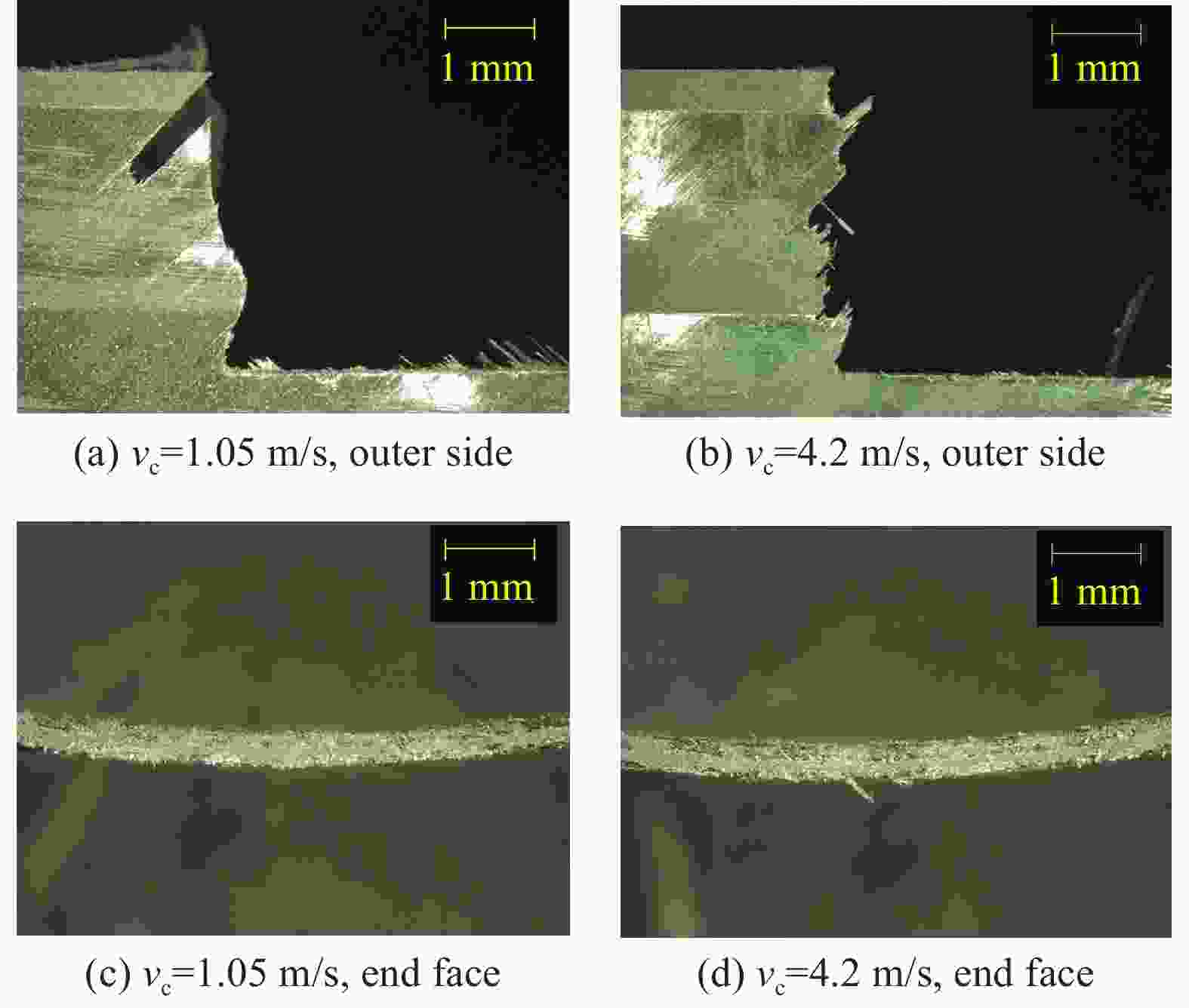
图 32 CFRP管端面铣削φ=40°时vc对形貌影响
Figure 32. Effect of vc on surface morphology when milling CFRP circular cell at φ=40°
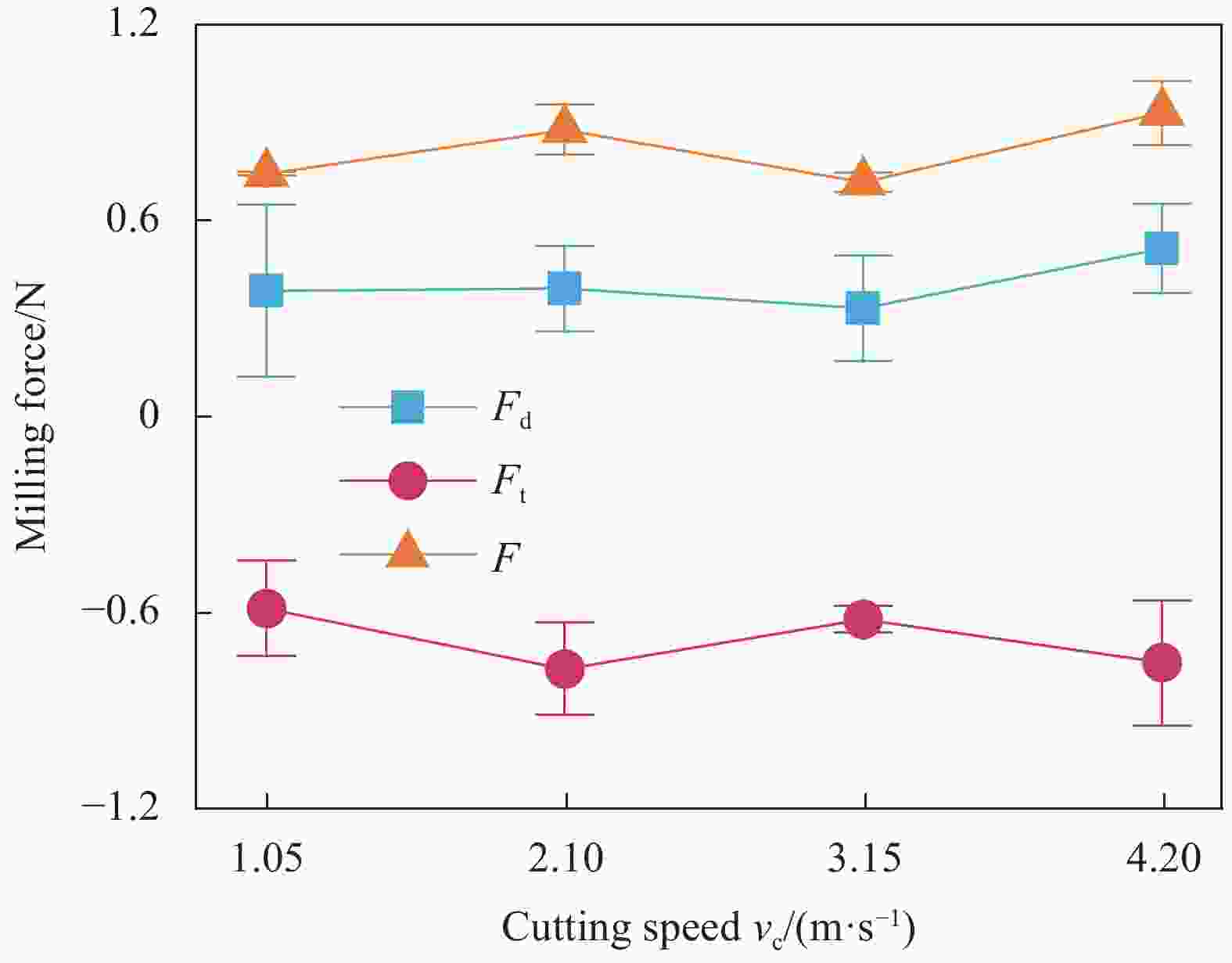
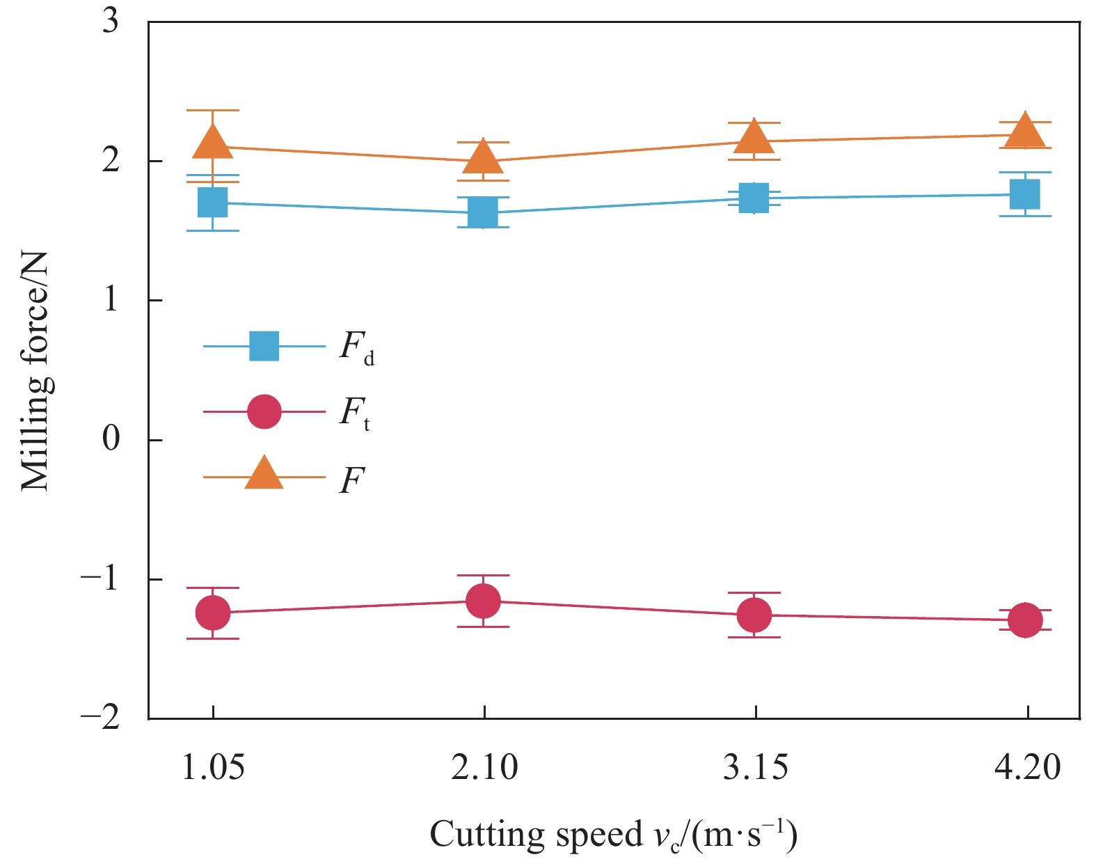
图 33 CFRP管端面铣削φ=40°时vc对力影响
Figure 33. Effect of vc on milling force when milling CFRP circular cell at φ=40°

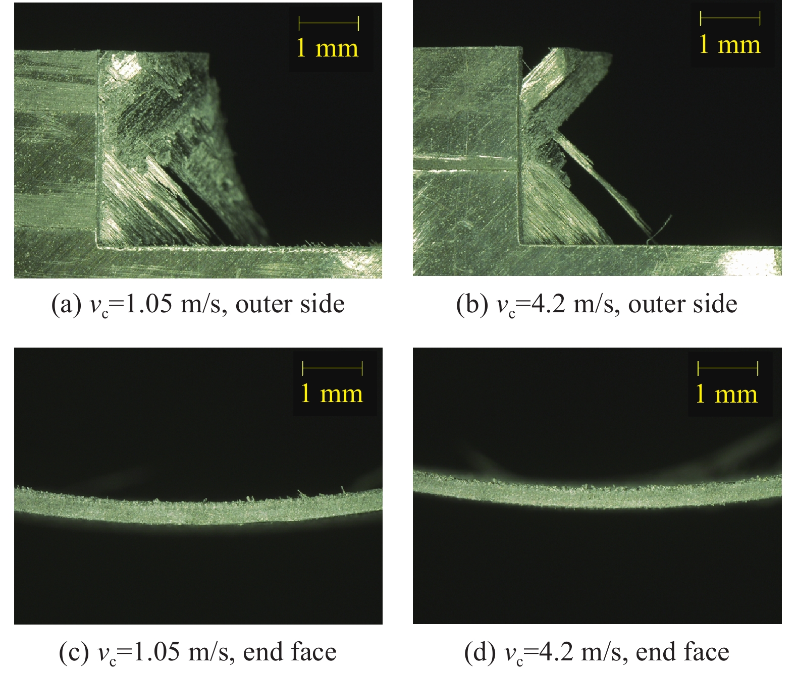
图 34 CFRP管端面磨削φ=100°时vc对形貌影响
Figure 34. Effect of vc on surface morphology when grinding CFRP circular cell at φ=100°
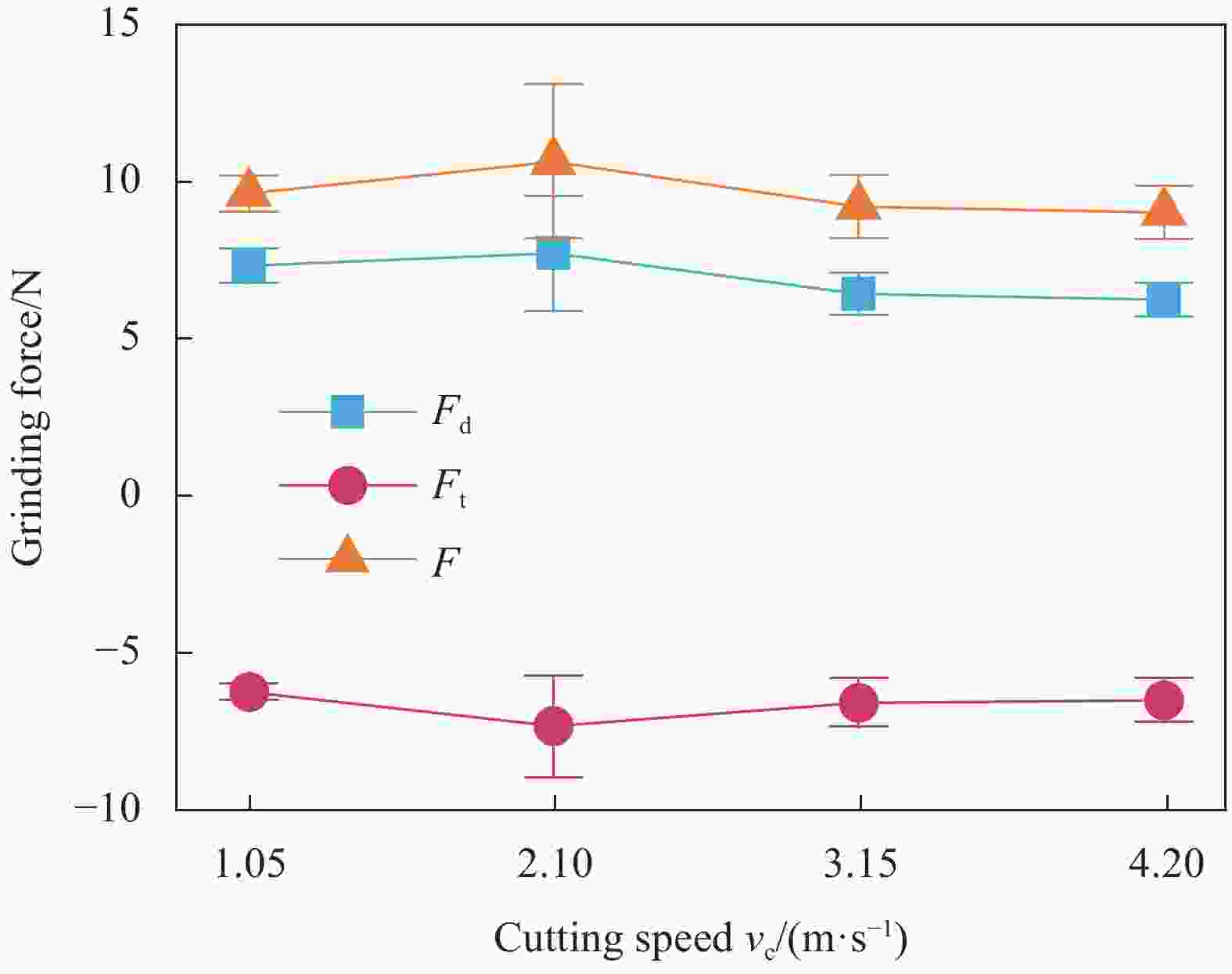
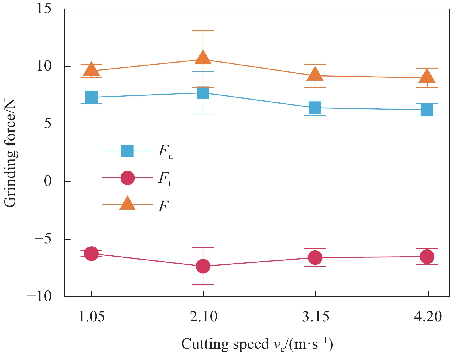
图 35 CFRP管端面磨削φ=100°时vc对力影响
Figure 35. Effect of vc on grinding force when grinding CFRP circular cell at φ=100°

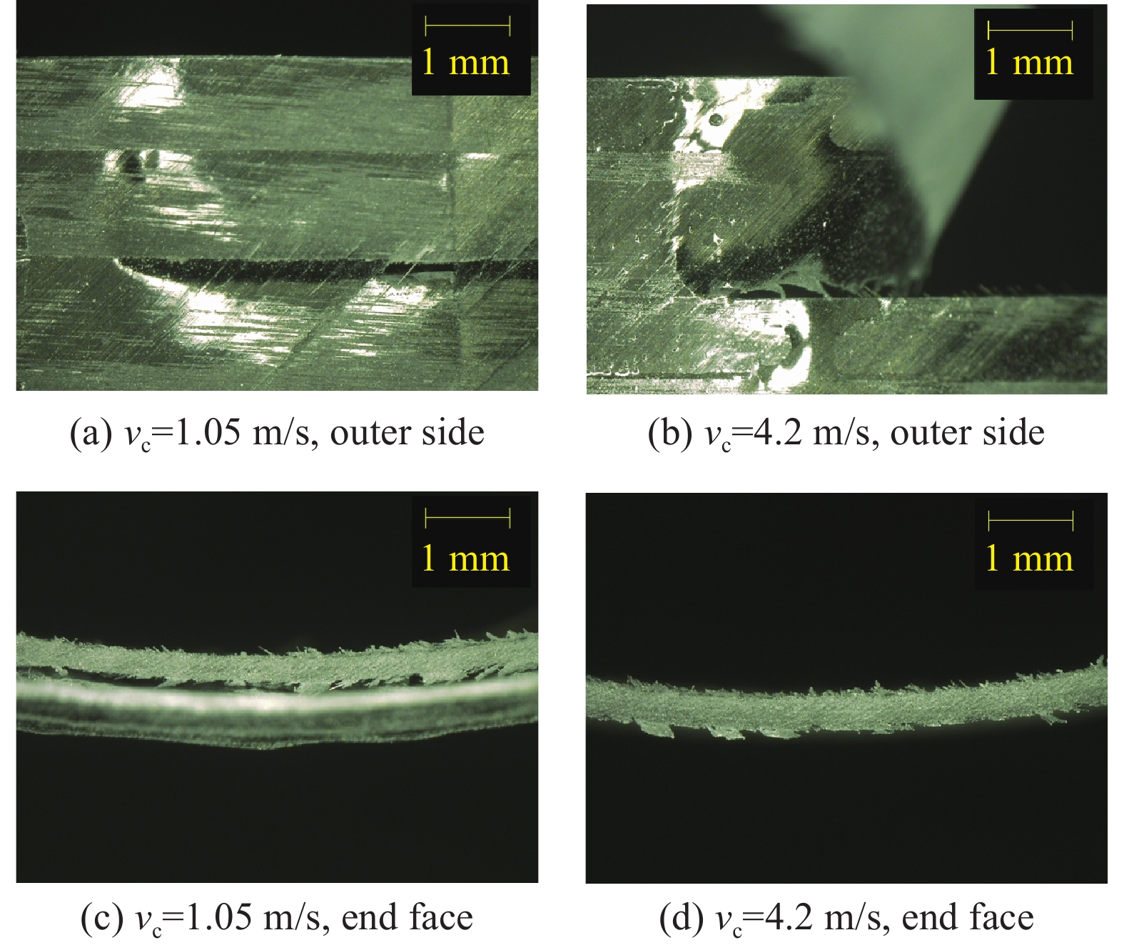
图 36 CFRP管端面铣削φ=100°时vc对形貌影响
Figure 36. Effect of vc on surface morphology when milling CFRP circular cell at φ=100°

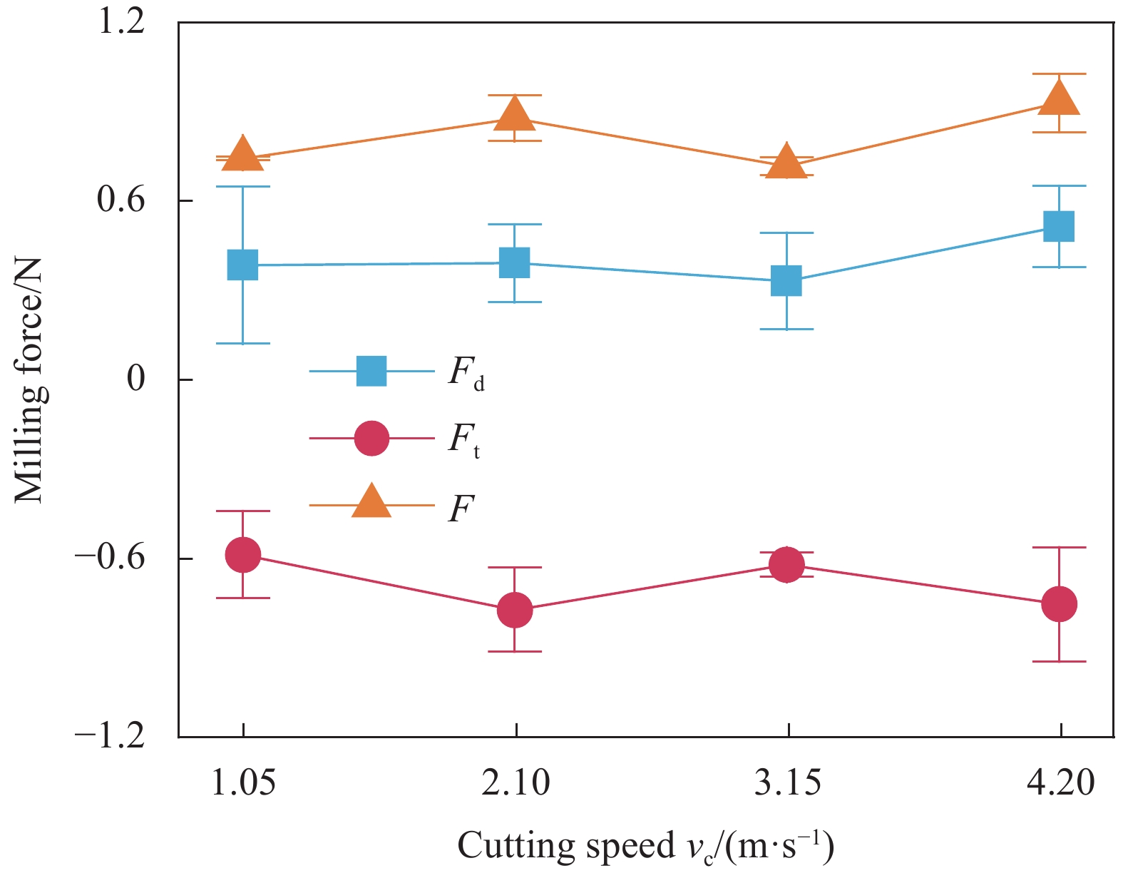
图 37 CFRP管端面铣削φ=100°时vc对力影响
Figure 37. Effect of vc on milling force when milling CFRP circular cell at φ=100°
表 1 CFRP复合材料单向带的材料参数
Table 1. Material parameters of unidirectional CFRP
Material parameter Value Longitudinal elastic modulus E1/GPa 135 Transverse elastic modulus E2/GPa 11.91 Poisson's ratio ν12 0.27 Longitudinal tensile strength S1/MPa 1421 Transverse tensile strength S2/MPa 33.8  下载: 导出CSV
表 2 端面加工实验工艺参数
Table 2. Experimental parameters of end face machining
No. φ/(°) e/mm f/(mm∙r−1) ap/mm vc/(m∙s−1) 1-6 40, 60, 80,
100, 120, 14016.486, 18.028, 19.755, 21.441, 22.913, 24.046 0.125 3 2.1 7-12 40, 100 16.486, 21.441 0.125 1, 2, 4 2.1 13-18 40, 100 16.486, 21.441 0.0625, 0.1875,
0.253 2.1 19-24 40, 100 16.486, 21.441 0.125 3 1.05, 3.15, 4.2 Notes: φ—Exit angle during end-face machining experiments; f—Real feed rate of tools, indicates the arc length of the CFRP circular cell wall actually removed by one revolution of the tools; ap—Axial cutting depth; vc —Cutting speed of tools.
下载: 导出CSV
-
[1] 史耀辉, 沈峰, 郝旭峰. 一种碳纤维管阵结构及其制作方法: 中国, 201810813952.3[P]. 2018-07-23.SHI Yaohui, SHEN Feng, HAO Xufeng. A structure of CFRP circular cell honeycomb and its manufacturing method: China, 201810813952.3[P]. 2018-07-23 (in Chinese). [2] 吴楠, 郝旭峰, 史耀辉, 等. 高精度碳纤维增强树脂复合材料夹层天线面板热变形影响参数仿真与实验[J]. 复合材料学报, 2020, 37(7): 1619-1628.WU Nan, HAO Xufeng, SHI Yaohui, et al. Simulation and experiment on thermal deformation influence parameters of high accuracy carbon fiber reinforced plastic sandwiched antenna panels[J]. Acta Materiae Compositae Sinica, 2020, 37(7): 1619-1628 (in Chinese). [3] 周星驰, 唐振刚, 周徐斌, 等. CFRP圆形胞元蜂窝芯层面外剪切模量[J]. 复合材料学报, 2018, 35(10): 2777-2785.ZHOU Xingchi, TANG Zhengang, ZHOU Xubin, et al. External shear modulus of CFRP circular cell honeycomb[J]. Acta Materiae Compositae Sinica, 2018, 35(10): 2777-2785 (in Chinese). [4] 李志宽, 吴锦武, 田文昊, 等. 基于夹层板理论的圆形孔蜂窝结构隔声量研究[J]. 声学技术, 2019, 38(2): 194-199.LI Zhikuan, WU Jinwu, TIAN Wenhao, et al. Study of the sound insulation of circular honeycomb structure based on sandwich platetheory[J]. Technical Acoustics, 2019, 38(2): 194-199 (in Chinese). [5] 贾振元, 毕广健, 王福吉, 等. 碳纤维增强树脂基复合材料切削机理研究[J]. 机械工程学报, 2018, 54(23): 199-208. doi: 10.3901/JME.2018.23.199JIA Zhenyuan, BI Guangjian, WANG Fuji, et al. The research of machining mechanism of carbon fiber reinforced plastic[J]. Journal of Mechanical Engineering, 2018, 54(23): 199-208 (in Chinese). doi: 10.3901/JME.2018.23.199 [6] ESPADAS-ESCALANTE J J, VAN DIJK N P, ISAKSSON P. A phase-field model for strength and fracture analyses of fiber-reinforced composites[J]. Composites Science and Technology, 2019, 174: 58-67. doi: 10.1016/j.compscitech.2018.10.031 [7] 张迅, 董志刚, 王毅丹, 等. Nomex蜂窝芯直刃尖刀超声切割表面微观形貌特征[J]. 机械工程学报, 2017, 53(19): 90-99. doi: 10.3901/JME.2017.19.090ZHANG Xun, DONG Zhigang, WANG Yidan, et al. Charization of surface microscopic of nomex honeycomb after ultrasonic assisted cutting[J]. Journal of Mechanical Engineering, 2017, 53(19): 90-99 (in Chinese). doi: 10.3901/JME.2017.19.090 [8] FLEISCHER J, TETI R, LANZA G, et al. Composite materials parts manufacturing[J]. CIRP Annals-Manufacturing Technology, 2018, 67(2): 603-626. doi: 10.1016/j.cirp.2018.05.005 [9] VOSS R, SEEHOLZER L, KUSTER F, et al. Influence of fibre orientation, tool geometry and process parameters on surface quality in milling of CFRP[J]. CIRP Journal of Manufacturing Science and Technology, 2017, 18: 75-91. doi: 10.1016/j.cirpj.2016.10.002 [10] WANG F J, ZHANG B Y, JIA Z Y, et al. Structural optimization method of multitooth cutter for surface damages suppression in edge trimming of carbon fiber reinforced plastics[J]. Journal of Manufacturing Processes, 2019, 46: 204-213. doi: 10.1016/j.jmapro.2019.09.013 [11] HINTZE W, HARTMANN D, SCHÜTTE C. Occurrence and propagation of delamination during the machining of carbon fibre reinforced plastics (CFRPs)—An experimental study[J]. Composites Science and Technology, 2011, 71(15): 1719-1726. doi: 10.1016/j.compscitech.2011.08.002 [12] HINTZE W, HARTMANN D. Modeling of delamination during milling of unidirectional CFRP[J]. Procedia CIRP, 2013, 8: 444-449. doi: 10.1016/j.procir.2013.06.131 [13] 王福吉, 殷俊伟, 贾振元, 等. CFRP复合材料铣削力、温度及表层损伤分析[J]. 机械工程学报, 2018, 54(3): 186-195. doi: 10.3901/JME.2018.03.186WANG Fuji, YIN Junwei, JIA Zhenyuan, et al. Measurement and analysis of cutting force, temperature and cutting-induced top-layer damage in edge trimming of CFRPs[J]. Journal of Mechanical Engineering, 2018, 54(3): 186-195 (in Chinese). doi: 10.3901/JME.2018.03.186 [14] 张高峰, 何杨, 鲁炎鑫, 等. 碳纤维增强复合材料低温冷风磨削试验研究[J]. 中国机械工程, 2016, 27(20): 2779-2784, 2790.ZHANG Gaofeng, HE Yang, LU Yanxin, et al. Experimental study on cryogenic cold air grinding of carbon fibre reinforced plastics[J]. China Mechanical Engineering, 2016, 27(20): 2779-2784, 2790 (in Chinese). [15] BOUDELIER A, RITOU M, GARNIER S, et al. Cutting force model for machining of CFRP laminate with diamond abrasive cutter[J]. Production Engineering, 2018, 12(2): 279-287. doi: 10.1007/s11740-018-0813-4 [16] TIAN J C, KANG R K, DONG Z G, et al. Multi-scale machining damages of CFRP circular cell honeycomb during end face machining[J]. Journal of Manufacturing Processes, 2023, 86: 282-293. doi: 10.1016/j.jmapro.2023.01.006 [17] 田俊超, 鲍岩, 董志刚, 等. 端面磨削复合材料管毛刺预测及验证[J]. 机械工程学报, 2022, 58(15): 63-74.TIAN Junchao, BAO Yan, DONG Zhigang, et al. Prediction and verification of burrs of face grinding CFRP circular cell[J]. Journal of Mechanical Engineering, 2022, 58(15): 63-74 (in Chinese). [18] WANG C Y, LIU G Y, AN Q L, et al. Occurrence and formation mechanism of surface cavity defects during orthogonal milling of CFRP laminates[J]. Composites Part B: Engineering, 2017, 109: 10-22. doi: 10.1016/j.compositesb.2016.10.015 [19] ABENA A, SOO S L, ESSA K. Modelling the orthogonal cutting of UD-CFRP composites: Development of a novel cohesive zone model[J]. Composite Structures, 2017, 168: 65-83. doi: 10.1016/j.compstruct.2017.02.030 [20] VOSS R, SEEHOLZER L, KUSTER F, et al. Analytical force model for orthogonal machining of unidirectional carbon fibre reinforced polymers (CFRP) as a function of the fibre orientation[J]. Journal of Materials Processing Technology, 2019, 263: 440-469 -

 下载:
下载:


 点击查看大图
计量
- 文章访问数: 116
- HTML全文浏览量: 53
- PDF下载量: 11
- 被引次数: 0
