Simulation of buckling and delamination propagation of composite laminates with fiber bridging
-
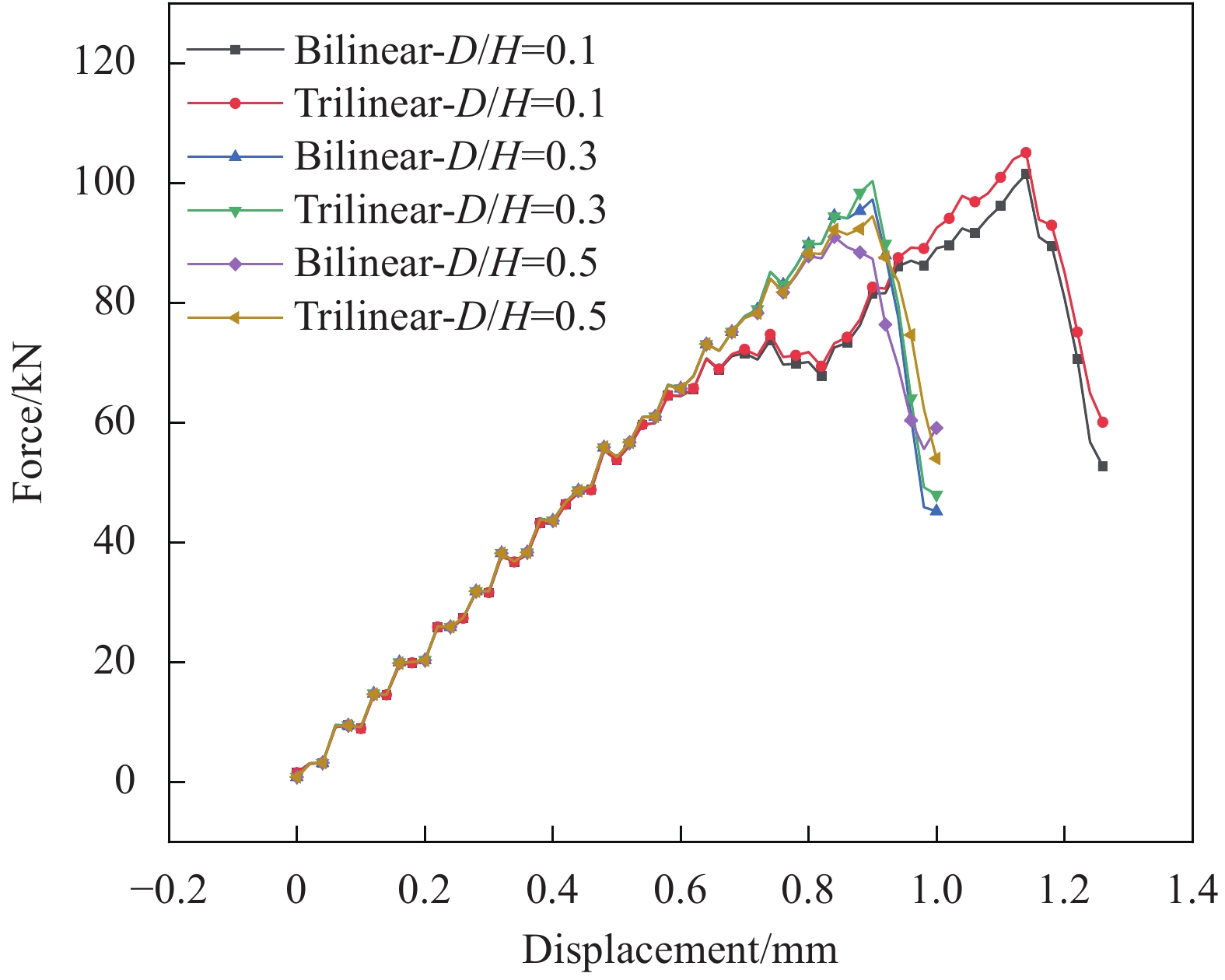
摘要: 纤维增强复合材料层合板由于层间力学性能弱,容易出现分层损伤。分层的扩展往往伴随着纤维桥联效应,纤维桥联能显著增大层合板尤其是多向层合板分层扩展的阻力。考虑纤维桥联效应的三线性内聚力模型能表征分层扩展实验中断裂韧性的“R曲线”特征,比传统的双线性模型能更为准确地描述复合材料的分层扩展行为。本论文基于三线性内聚力模型,对含圆形分层复合材料层合板的轴向压缩进行数值模拟,探讨纤维桥联效应对分层扩展及后屈曲行为的影响规律。研究结果发现,纤维桥联对层合板的屈曲载荷影响较小;混合屈曲模式下,三线性模型预测的上下子板相对法向位移明显低于双线性模型;相同分层深度下,三线性模型预测的层合板后屈曲更早转变为整体屈曲模式。随着分层深度的增加,层合板的屈曲模式由局部屈曲逐步过渡为混合屈曲和整体屈曲;当分层深度较浅时,I型分层扩展占主导;随着分层深度的增加,I型分层逐渐减弱,而II型和III型分层扩展则显著增强;当分层接近板中面时,I型分层停止扩展,以II型及III型分层为主。Abstract: Fiber reinforced composite laminates are susceptible to delamination damage due to relatively weak inter-laminar mechanical properties. The growth of delamination is always accompanied by fiber bridging, which can significantly increase the resistance of delamination propagation, especially in the case of multidirectional lami-nates. Compared with the traditional bilinear model, a trilinear cohesive zone model with fiber bridging effects can describe the “R curve” characteristic of the fracture toughness shown in the delamination test, and consequently better characterize the delamination propagation behavior of composite laminates. In order to evaluate the effects of fiber bridging on the behaviors of delamination growth and post-buckling in composite laminates, a trilinear cohesive zone model was built to investigate the compressive behavior of composite laminates with a circular delamination. The results demonstrate that, fiber bridging has little effect on the buckling load of the laminates. The relative deflection between the upper and lower sub-laminate predicted by the trilinear model is much smaller than that predicted by the bilinear model under mixed buckling mode. The buckling mode predicted by the trilinear model transits to global buckling earlier than that predicted by the bilinear model at identical delamination depth. The post-buckling modes change from local buckling mode to mix mode buckling and finally global buckling with the increase of delamination depth. For shallow delamination, mode I delamination is prominent. With the increase of delamination depth, the mode I delamination gradually disappears, while the mode II and III delamination propagation increases significantly. For delamination close to the mid-plane of the laminate, the delamination propagation is dominated by mode II and mode III, without mode I growth.
-
糖尿病是一种严重威胁人类健康的慢性病。全球糖尿病患者人数从1980年的1.08亿增加到2023年的5.37亿。葡萄糖传感器在糖尿病的诊断和治疗中起着重要作用[1-3]。糖尿病患者要定期检测生理血糖水平,并将血糖水平维持在正常浓度范围内。而且,准确评价食品中的葡萄糖含量对维持糖尿病患者血液中葡萄糖的生理水平至关重要[4-5]。食品和饮料中葡萄糖含量的信息对生产者和消费者都有参考价值。葡萄糖检测在葡萄酒酿造工艺和乳制品工业的发酵过程中是至关重要的[4-5]。迄今为止,检测葡萄糖的方法很多。在各种分析方法中,电化学葡萄糖传感器具有灵敏度高、选择性好、操作简单、成本低等优点,并能实现自我监控和床边血糖检测[5-8]。基于酶的电化学葡萄糖传感器已经商业化并取得了巨大的成功。由于自然酶容易受到环境(温度、湿度、酸碱度等)影响,非酶葡萄糖传感器受到广泛关注[1-3, 8]。
金属-有机框架(Metal-origanic frameworks,MOFs)材料是一类新兴的多孔材料,存在电化学传感器应用潜力[9-12]。它们具有金属活性位点丰富、表面积大、结构多样、孔径可调和功能可调等优点。Li等[13]开发了Co-MOF纳米片阵列构建葡萄糖检测平台,其灵敏度为
10886 μA·L/(mmol·cm2),检测极限为1.3 nmol/L。Khan等[14]以MOF-199为前驱体合成 CuO/C复合材料,催化葡萄糖的氧化反应。Cu-MOFs修饰电极在0.06至5 mmol/L的线性范围内,对葡萄糖氧化显示出相对较好的电催化活性,其灵敏度为89 mA·L/(mmol·cm2),检测限为10.5 nmol/L。在另一份报告中,球形Ni-MOFs 颗粒在单独使用时表现出较差的电化学葡萄糖传感性能[15]。然而,当它们与碳纳米管的杂交后,对葡萄糖检测的灵敏度为13.85 mA·L/(mmol·cm2),检测极限为0.82 mmol/L,线性范围为1至1.6 mmol/L。此外,Zha等[16]开发了基于NiCo-MOF/C复合材料的无创血糖检测平台,其高灵敏度和检测极限分别为2701.29 μA·L/(mmol·cm2)和0.09 μmol/L。MOFs衍生复合材料在电化学葡糖糖传感器领域得到一定程度的应用。另一方面,随着实时传感设备和护理点设备的发展需要,经济的、可靠的、规模化的电极制备方法受到广泛关注[17]。作为一种商业化电极制备方法,丝网印刷技术具有设备简单、图案设计灵活、操作简单、经济等特点[17]。该技术在生物传感器领域,尤其指尖血糖检测中取得商业成功。Li等[18]实验组通过丝网印刷技术开发了一种具有优化三电极配置的多功能电化学平台,检测葡萄糖浓度。Ji等[19]实验组基于智能手机的循环伏安系统,采用石墨烯修饰的丝网印刷电极检测葡萄糖浓度。因此,本文在室温条件合成Co基MOFs(Co-ZIF-67),采用丝网印刷技术,制备了Co-ZIF-67修饰的商业银-碳电极,研究其对葡萄糖的传感性能。
1. 实验方法
1.1 原材料与试剂
六水硝酸钴(Co(NO3)2·6H2O,99.5%) 、聚乙烯醇(PVA,92%~94%)、聚乙烯吡咯烷酮(PVP,K23-27)、甲醇(CH2OH,99.5%)、3-(N-吗啉)丙磺酸钠(MOPs-Na,C7H14NO4SNa,99.5%)、羟乙基纤维素(HEC)、丙烯酰胺(C3H5NO,99.0%)、抗坏血酸(C6H6O8,99.0%)、半乳糖(C6H12O6,99.0%)、羧甲基纤维素((C6+2yH7+x+2yO2+x+3yNay)n)、柠檬酸(C6H8O7,99.5%)、葡萄糖(C6H12O6,96%)和葡聚糖(DEAE-Dextran,70 kDa)购自上海阿拉丁生化科技股份有限公司。过硫酸铵(H8N2O8S2,98.5%)购自上海麦克林生化科技有限公司。
1.2 材料表征
采用X-射线衍射仪(Smartlab9kw,Rigaku)对样品的物相和晶体结构进行表征。通过X射线光电子能谱(ESCALAB 250Xi,赛默飞)对样品的元素和表面信息进行分析。采用扫描电子显微镜扫描电镜(SEM,SU8100,日立)和透射电子显微镜(TEM,JEM2100,JEOL)对样品进行形貌表征。通过电化学工作站(CH650E,上海辰华仪器有限公司)评估修饰电极对葡萄糖的电化学传感性能。本研究配制了不同浓度葡萄糖(0.1~0.5 mmol/L)的0.1 mol/L氢氧化钠溶液。
1.3 Co-ZIF-67及Co-ZIF-67修饰电极的制备
Co-ZIF-67纳米材料在室温条件下制备而成。合成过程中,12 mmol/L的Co(NO3)2·6H2O完全溶解于100 mL甲醇中,记为溶液 A;48 mmol/L的2-甲基咪唑溶解于
1000 mL甲醇中,记为溶液 B。溶液B迅速地加入到溶液A中,形成混合液C。该混合液C磁力搅拌10 min后,在室温环境下静置24 h,形成沉淀物。采用甲醇清洗沉淀物,并在60℃干燥过夜,得到紫色Co-ZIF-67粉末。把20 mg Co-ZIF-67在1 mL的超纯水中超声30 min,得到溶液D。0.55 g MOPs 钠盐,0.075 g的羟乙基纤维素,1.75 g丙烯酰胺和0.05 g过硫酸铵分别溶解于25 mL的超纯水中,磁力搅拌2 h后形成混合浆料。将1 mL溶液D与9 mL浆料磁性搅拌1 h后,形成 Co-ZIF-67丝网印刷油墨。
将Co-ZIF-67油墨均匀的丝网印刷在商业银-碳电极的工作区域,经烘干(45℃,15 min)、贴亲水膜、裁剪,制备了便携式一次性条形葡萄糖检测电极。该电极包括一个工作电极,一个对电极。工作电极的表面积为3.78 mm×0.252 mm=
0.9526 mm2。每个电极所分析的溶液量为10 μL。亲水膜的作用是形成流道,吸附检测样品。Co-MOF修饰电极的制备过程见图1。2. 结果与讨论
2.1 Co-ZIF-67物相分析
采用XRD技术研究了Co-ZIF-67的晶体结构。从图2(a)可以看出,在2θ=10.4°、12.7°、14.7°、16.4°、18.0°、22.1°、24.4°、26.5°、29.8°、30.5°和32.5°时,分别对应于ZIF-67的(002)、(112)、(022)、(013)、(222)、(114)、(233)、(134)、(044)、(244)、(235)晶面,这与已报道的ZIF-67样品的XRD结果一致[20-22]。采用X射线光电子能谱(XPS)对Co-ZIF-67的表面信息进行了分析。从图2(b)可以看出,样品包含Co2p、O1s、N1s、C1s、Co3s和Co3p核能级区域。Co2p和 C1s的XPS精细谱分别如图2(c)和图2(d)所示。Co2p精细谱含有两个主峰,其中780.1 eV峰来自Co2p3/2;795.3 eV峰来自Co2p1/2。激振峰分别位于785.5和801.7 eV。除了主峰,C1s精细谱还有两个拟合峰。结合能位于286.2和288.1 eV,分别归属于C—N和C—O。上述结果表明,Co-ZIF-67已经被成功制备。采用SEM和TEM研究了样品的形貌。如图3(a)~3(f)所示,Co-ZIF-67呈现多面形,且尺寸分布相对较窄。
2.2 Co-ZIF-67的电催化性能
采用循环伏安(CV)技术评估了Co-ZIF-67修饰电极的电化学性能。图4(a)是Co-ZIF-67修饰电极在50 mV/s扫速时对0.3 mmol/L葡萄糖在不同pH值溶液中的响应信号。很明显,当pH=13时,Co-ZIF-67表现出对葡萄糖较大的催化活性。当葡萄糖浓度增加时,Co-ZIF-67修饰电极电流信号也随之增强(图4(b))。然而,信号的区分度不大。图4(c)是Co-ZIF-67修饰电极在不同扫速(10、30、50、70、90、110和130 mV/s)下对葡萄糖信号的变化。随着扫速增大,电流信号明显得到加强。将0.5 V电流强度与扫描速度的算术平方根进行拟合,其线性关系为:I (μA/cm2)=0.14v1/2–0.12 (R2=0.988,R2为决定系数)。这说明Co-ZIF-67修饰电极对应的电化学反应是受扩散控制的[23]。
![]() 图 4 Co-ZIF-67修饰电极在不同pH值(a)、葡萄糖浓度(b)、扫速(c)对葡萄糖的CV测试曲线;(d)扫描速率(v)的算数平方根与电流(I) (0.5 V)之间的线性关系Figure 4. CV curves of Co-ZIF-67 modified electrodes with different pH (a), glucose concentrations (b), and scan rates (c); (d) Corresponding linear relationship between the arithmetic square root of the scanning rate (v) and current (I, 0.5 V)R2—The coefficient of determination, which determinates the linear relationship of the fit curve
图 4 Co-ZIF-67修饰电极在不同pH值(a)、葡萄糖浓度(b)、扫速(c)对葡萄糖的CV测试曲线;(d)扫描速率(v)的算数平方根与电流(I) (0.5 V)之间的线性关系Figure 4. CV curves of Co-ZIF-67 modified electrodes with different pH (a), glucose concentrations (b), and scan rates (c); (d) Corresponding linear relationship between the arithmetic square root of the scanning rate (v) and current (I, 0.5 V)R2—The coefficient of determination, which determinates the linear relationship of the fit curve采用差分脉冲伏安法(Differential pulse voltammetry,DPV)进一步评估了Co-ZIF-67修饰电极的电化学性能。如图5(a)所示,在0~0.5 mmol/L 葡萄糖溶液中观测了Co-ZIF-67修饰电极表面的氧化和还原反应,其对葡萄糖可能的催化机制为:Co-ZIF-67修饰电极对葡萄糖表现出较CV更强的DPV响应信号,这也表明,Co-ZIF-67对葡萄糖确实存在电催化效果[24-27]。此外,溶液中没有葡萄糖时,Co-ZIF-67修饰电极在0.4~0.6 V有一个不明显的氧化还原峰。随着葡萄糖浓度的增加,该修饰电极的响应信号也随之增强,氧化还原峰变得更加明显,这主要是由于高电位下碱性溶液中Co-ZIF-67中Co2+被氧化为Co3+。此时,Co3+因从葡萄糖得电子(变为Co2+)并不断将葡萄糖氧化为葡萄糖酸从而产生电流信号[28-29]。因此,Co-ZIF-67修饰电极具有较好的电催化性能。如图5(b)所示,Co-ZIF-67修饰电极的电流平均值(0.55 V)与葡萄糖浓度呈线性关系,其线性方程为:I (μA/cm2)=−3.730×C(mmol/L) − 5.720 (R2=
0.9639 )。![]() 图 5 (a) Co-ZIF-67修饰电极在不同葡萄糖浓度中的差分脉冲伏安法(DPV)测试曲线;(b)每5支Co-ZIF-67修饰电极在0.55 V电位对不同浓度葡萄糖的平均电流响应信号;(c) Co-ZIF-67修饰电极对不同葡萄糖浓度的安培响应;(d)每5支电极对不同葡萄糖浓度的平均响应电流(取第15 s数值)Figure 5. (a) Differential pulse voltammetry (DPV) curves of Co-ZIF-67 modified electrodes in the presence of glucose; (b) Linear relationship between average DPV current density response and different glucose concentrations of every five electrodes at 0.55 V; (c) Amperometric response of Co-ZIF-67 modified SPEs to different glucose concentration; (d) Corresponding linear curve of average current density of five electrodes in the 15th s to glucose concentrations
图 5 (a) Co-ZIF-67修饰电极在不同葡萄糖浓度中的差分脉冲伏安法(DPV)测试曲线;(b)每5支Co-ZIF-67修饰电极在0.55 V电位对不同浓度葡萄糖的平均电流响应信号;(c) Co-ZIF-67修饰电极对不同葡萄糖浓度的安培响应;(d)每5支电极对不同葡萄糖浓度的平均响应电流(取第15 s数值)Figure 5. (a) Differential pulse voltammetry (DPV) curves of Co-ZIF-67 modified electrodes in the presence of glucose; (b) Linear relationship between average DPV current density response and different glucose concentrations of every five electrodes at 0.55 V; (c) Amperometric response of Co-ZIF-67 modified SPEs to different glucose concentration; (d) Corresponding linear curve of average current density of five electrodes in the 15th s to glucose concentrations采用安培响应技术在Co-ZIF-67修饰电极上对葡萄糖的传感性能做了进一步的评估。图5(c)显示随着电解质溶液中葡萄糖浓度的增加,响应电流随之增强。安培响应电流与葡萄糖浓度之间呈线性关系(图5(d)),其方程为:I (μA/cm2)=−1.390×C(mmol/L)−2.630 (R2=
0.9504 )。经过处理,Co-ZIF-67修饰电极对葡萄糖的检测灵敏度为1390 nA·L/(mmol·cm2),检测限为0.58 μmol/L (S/N=3),线性范围为0.1~0.5 mmol/L。值得一提的是,与已报道的电极相比,Co-ZIF-67修饰电极的灵敏度具有较大的优势,如表1所示[27, 29-34]。表 1 Co-ZIF-67修饰电极及其他电极的葡萄糖传感性能Table 1. Glucose sensing performance of Co-ZIF-67-modified electrodes and other previously reported electrodesType of electrode Sensitivity/(μA·L·mmol−1·cm−2) Detection limit/(μmol·L−1) Linear range/(mmol·L−1) Ref. Ag NPs/MOF-74(Ni) 1290 4.7 0.01-4 [27] NF/NiCo2O4 NWs@Co3O4 NPs 8163.2 – 0.001-1.7 [29] CuCo-MOF 6861 0.12 – [30] Ni2Co1-BDC/GCE 3925.3 0.29 0.0005 -2.8995 [31] Ni/Co(HHTP)MOF/CC 3250 0.1 0.0003 -2.312[32] MIL-88A@NiFe-PB 1963.2 0.12 0.005-1 [33] Ni3(HHTP)2/CNT 4774 4.1 0.004-3.9 [34] Co-MOFs/SPEs 1.393 0.58 0.1-0.5 This work Notes: CC—Carbon cloth; BDC—1, 4-benzenedicarboxylic acid; GCE—Glassy carbon electrode; HHTP—2, 3, 6, 7, 10, 11-hexahydroxytriphenylene; MIL—Materials from Institute Lavoisier; PB—Prussian blue; CNT—Carbon nanotubes; NF—Nickel foam; NWs—Nanowires; NPs—Nanoparticles; SPEs—Screen-printing electrodes. 2.3 抗干扰性、稳定性和重现性
图6(a)描述了Co-ZIF-67修饰电极抗干扰性能。从图上可以看出,干扰物质抗坏血酸(AA,3 mmol/L)、艾考糊精(INN,0.164 mol/L)、半乳糖(GAL,8 mmol/L)、谷胱甘肽(GSH,30 mmol/L)、麦芽糖(MAL,0.584 mol/L)引起的响应电流变化分别为−3.9%、−14.3%、−19.3%、−14.6%和−8.4%。与干扰物质相比,滴加0.1 mmol/L葡萄糖溶液时电流响应的显著变化表明。因此,Co-ZIF-67修饰电极具有较强的抗干扰能力。随后,通过长时间空气存放观察Co-ZIF-67修饰电极对0.1 mmol/L 葡萄糖的电流响应来评估的其稳定性。如图6(b)所示,Co-ZIF-67修饰电极表现出良好的稳定性。16天后,该电极仍然具有96%的初始响应。重现性是对电极的一个重要衡量标准。如图6(c)所示,Co-ZIF-67修饰电极的相对标准方差(Relative standard deviation,RSD)仅为10%,这说明该电极具有较好的重现性。
![]() 图 6 (a)干扰检查:5支Co-ZIF-67修饰电极 对0.1 mmol/L 葡萄糖(GLU)、0.164 mol/L 艾考糊精(INN)、9 mmol/L 半乳糖(GAL)、30 mmol/L谷胱甘肽(GSH)和0.584 mol/L 麦芽糖(MAL) 的平均安培响应;(b)稳定性:每5支Co-ZIF-67修饰电极在第1 d、4 d、7 d、10 d、13 d和16 d内对0.1 mmol/L 葡萄糖的安培响应信号;(c)重现性:10支Co-ZIP-67修饰电极对0.1 mmol/L 葡萄糖的响应Figure 6. (a) Interference examination: Average amperometric responses of five CuO nanomaterials modified SPEs to 0.1 mmol/L glucose (GLU), 0.164 mol/L alcodextrin (INN), 9 mmol/L galactose (GAL), 30 mmol/L glutathione (GSH) and 0.584 mol/L maltose (MAL); (b) Stability of every 5 Co-ZIF-67 modified electrodes to 0.1 mmol/L glucose on the 1st, 4th, 7th, 10th, 13th and 16th days; (c) Reproducibility of Co-ZIF-67 modified electrodes to 0.1 mmol/L glucose
图 6 (a)干扰检查:5支Co-ZIF-67修饰电极 对0.1 mmol/L 葡萄糖(GLU)、0.164 mol/L 艾考糊精(INN)、9 mmol/L 半乳糖(GAL)、30 mmol/L谷胱甘肽(GSH)和0.584 mol/L 麦芽糖(MAL) 的平均安培响应;(b)稳定性:每5支Co-ZIF-67修饰电极在第1 d、4 d、7 d、10 d、13 d和16 d内对0.1 mmol/L 葡萄糖的安培响应信号;(c)重现性:10支Co-ZIP-67修饰电极对0.1 mmol/L 葡萄糖的响应Figure 6. (a) Interference examination: Average amperometric responses of five CuO nanomaterials modified SPEs to 0.1 mmol/L glucose (GLU), 0.164 mol/L alcodextrin (INN), 9 mmol/L galactose (GAL), 30 mmol/L glutathione (GSH) and 0.584 mol/L maltose (MAL); (b) Stability of every 5 Co-ZIF-67 modified electrodes to 0.1 mmol/L glucose on the 1st, 4th, 7th, 10th, 13th and 16th days; (c) Reproducibility of Co-ZIF-67 modified electrodes to 0.1 mmol/L glucose2.4 血清测试
为了研究Co-ZIF-67修饰电极在实际样品中检测葡萄糖的性能,我们进行了加标回收实验(拜安进血糖仪(拜安进血糖试纸(葡萄糖脱氢酶),拜耳公司))。将血清稀释在NaOH溶液中,血清浓度为0.12 mmol/L。如表2所示,葡萄糖的回收率在93.97%~101.5%,RSD小于6.2%。这也表明Co-ZIF-67修饰电极具有潜在应用。
表 2 Co-ZIF-67修饰的Ag-C电极检测血清样品的葡萄糖含量(n=3)Table 2. Glucose detection in human serum samples using Co-ZIF-67 modified Ag-C electrodes (n=3)Sample Serum glucose/(mmol·L−1) Added glucose/(mmol·L−1) Detected glucose/(mmol·L−1) RSD/% Recovery rate/% Human
serum0.12 0.18 0.29 6.20 93.97 0.28 0.39 4.37 101.5 0.36 0.47 3.90 98.97 Note: RSD—Relative standard deviation. 3. 结 论
(1)基于室温合成的Co-ZIF-67,采用丝网印刷技术批量构建了Co-ZIF-67修饰的商业银-碳电极。
(2) Co-ZIF-67修饰电极表现出优异的葡萄糖电催化性能:0.58 μmol/L的检测极限,1.393 μA·L/(mmol·cm2)的灵敏度,高的抗干扰性,96%的空气稳定性。
(3)研究表明,Co-ZIF-67的低能耗合成及其Co-ZIF-67修饰电极的批量化制备为葡萄糖传感器的发展提供一个可参考的方向。
-
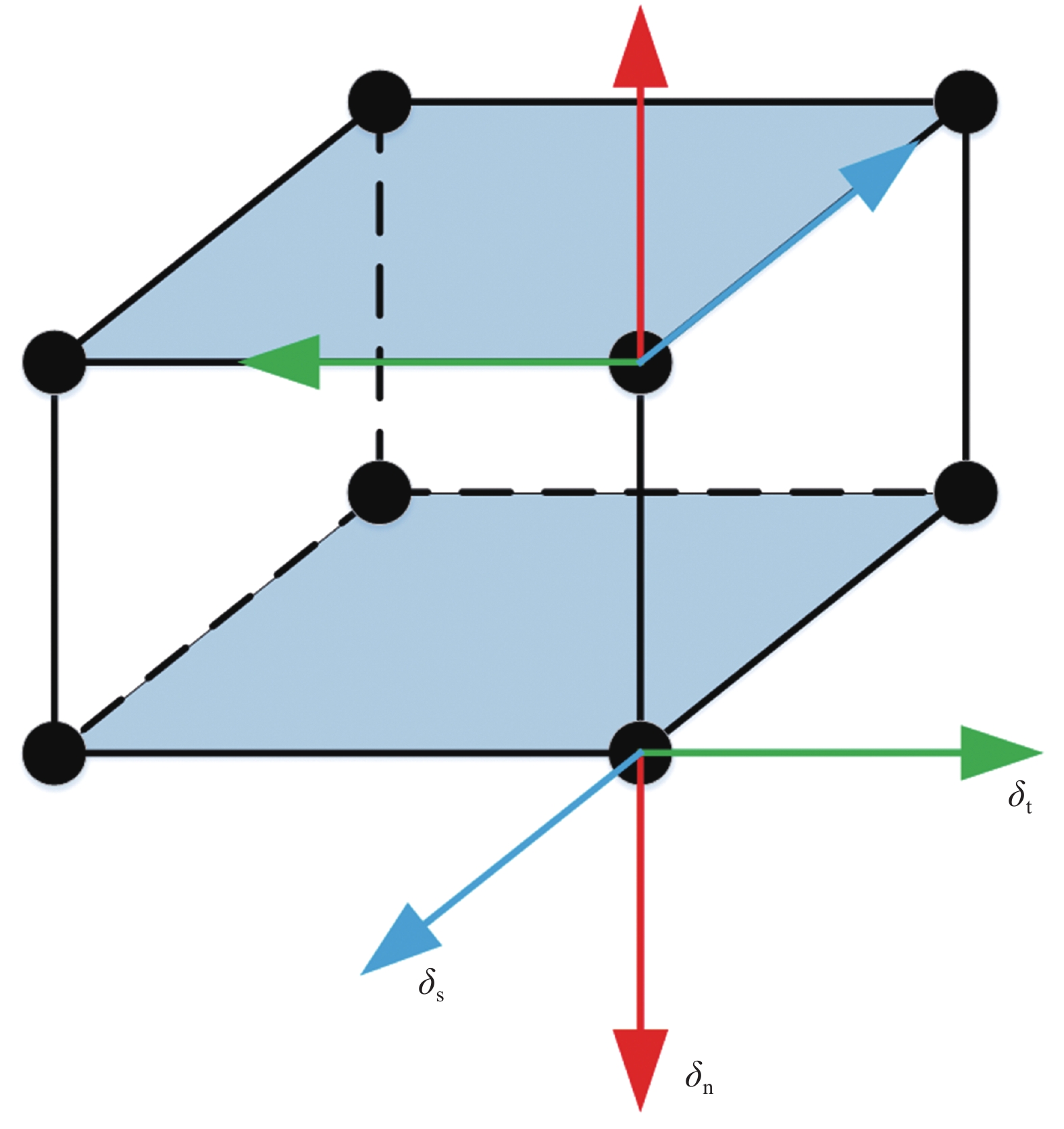
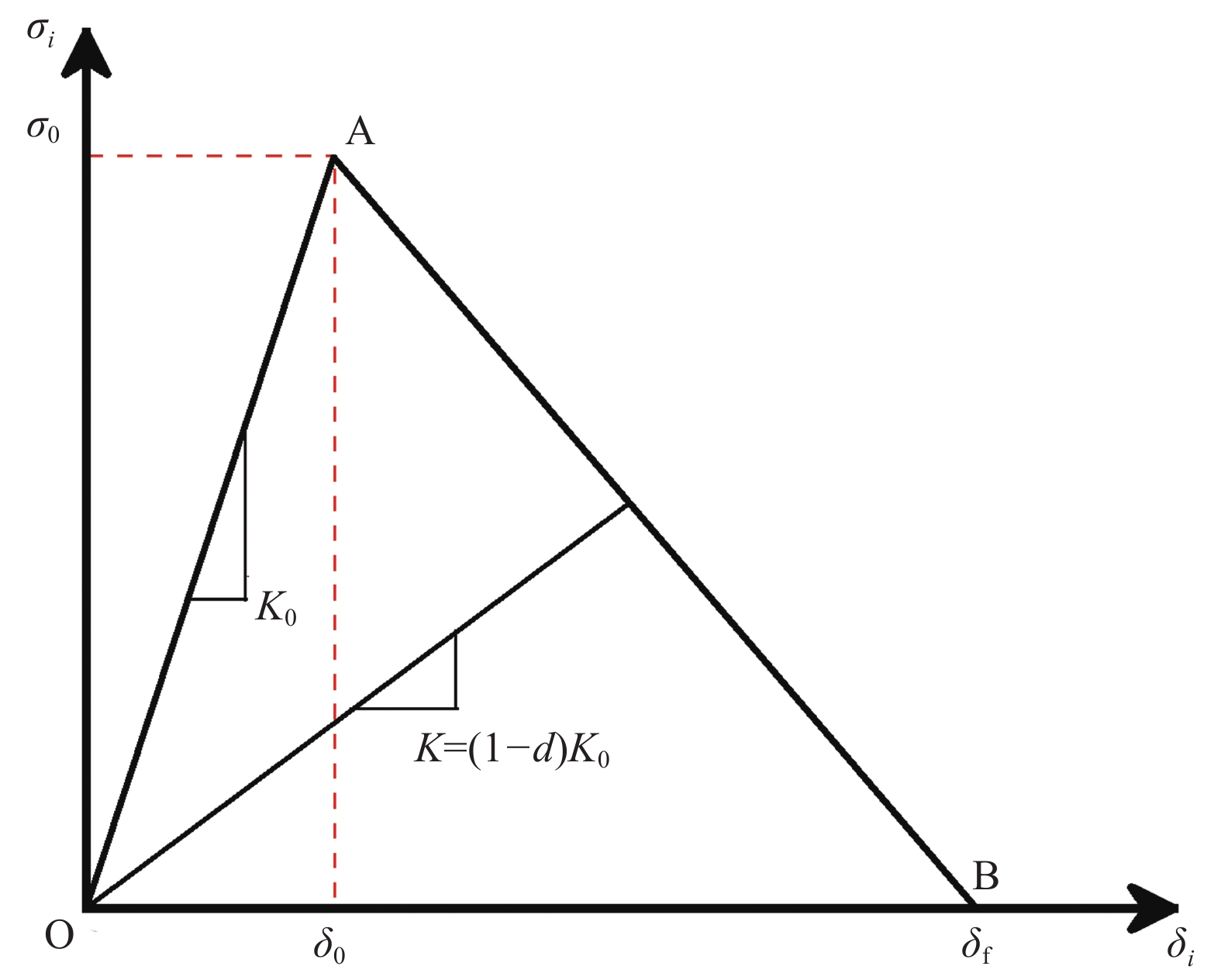
图 2 双线性内聚力模型
Figure 2. Bilinear cohesive zone model
σi, δi (i = n, s, t)—Traction and relative displacement in the normal and tangential directions of the cohesive element; K— Stiffness of the cohesive element; K0—Initial stiffness of the cohesive element; d—Damage coefficient; σ0, δ0—Traction and relative displacement at the initial moment of element injury; δf—Relative displacement at element failure
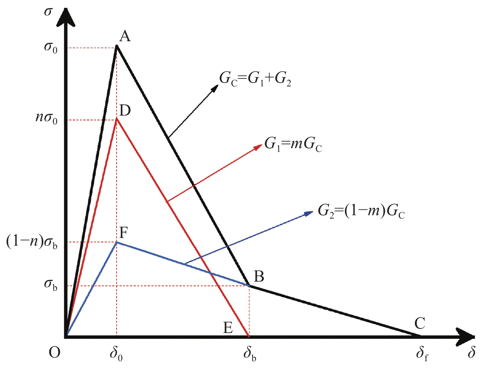
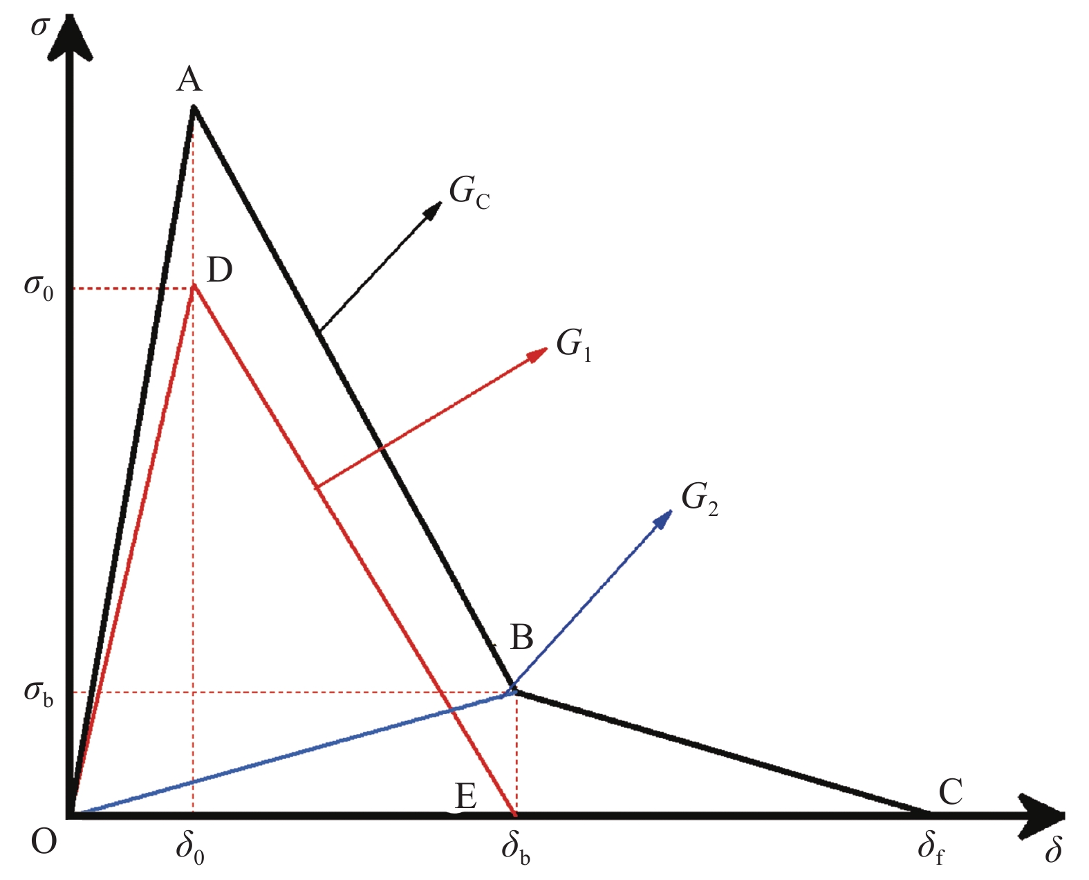
图 3 传统三线性内聚力模型
Figure 3. Traditional trilinear cohesive zone model
σb, δb—Traction force and relative displacement at matrix failure; G1—Fracture toughness of the matrix; G2—Fracture toughness of bridged fibers; GC—Overall fracture toughness; m—Ratio of matrix fracture toughness to overall fracture toughness; n—Ratio of bridged fibers fracture toughness to overall fracture toughness
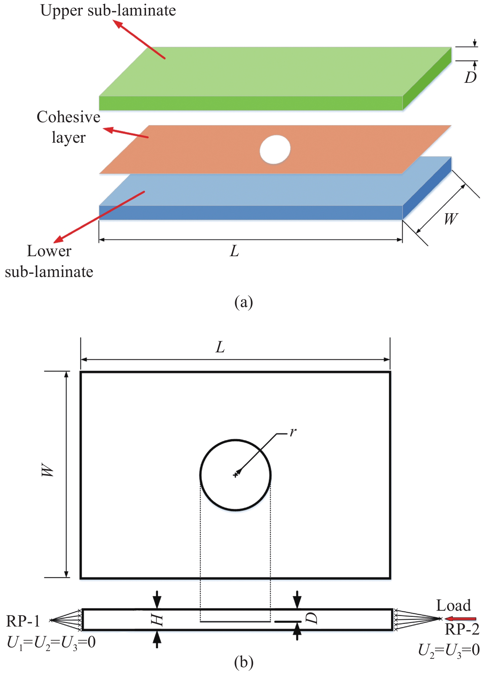
图 5 含圆形分层的层合板示意图:(a) 几何模型构成;(b)边界条件
Figure 5. Diagram of laminates with a circular delamination: (a) Composition of the geometric model; (b) Boundary conditions
D—Delamination depth; L, W—Length and width of finite element model; H—Thickness of finite element model; r—Radius of the initial delamination; RP-1, RP-2—Reference points for applying the load; U1, U2, U3—Displacement in three directions
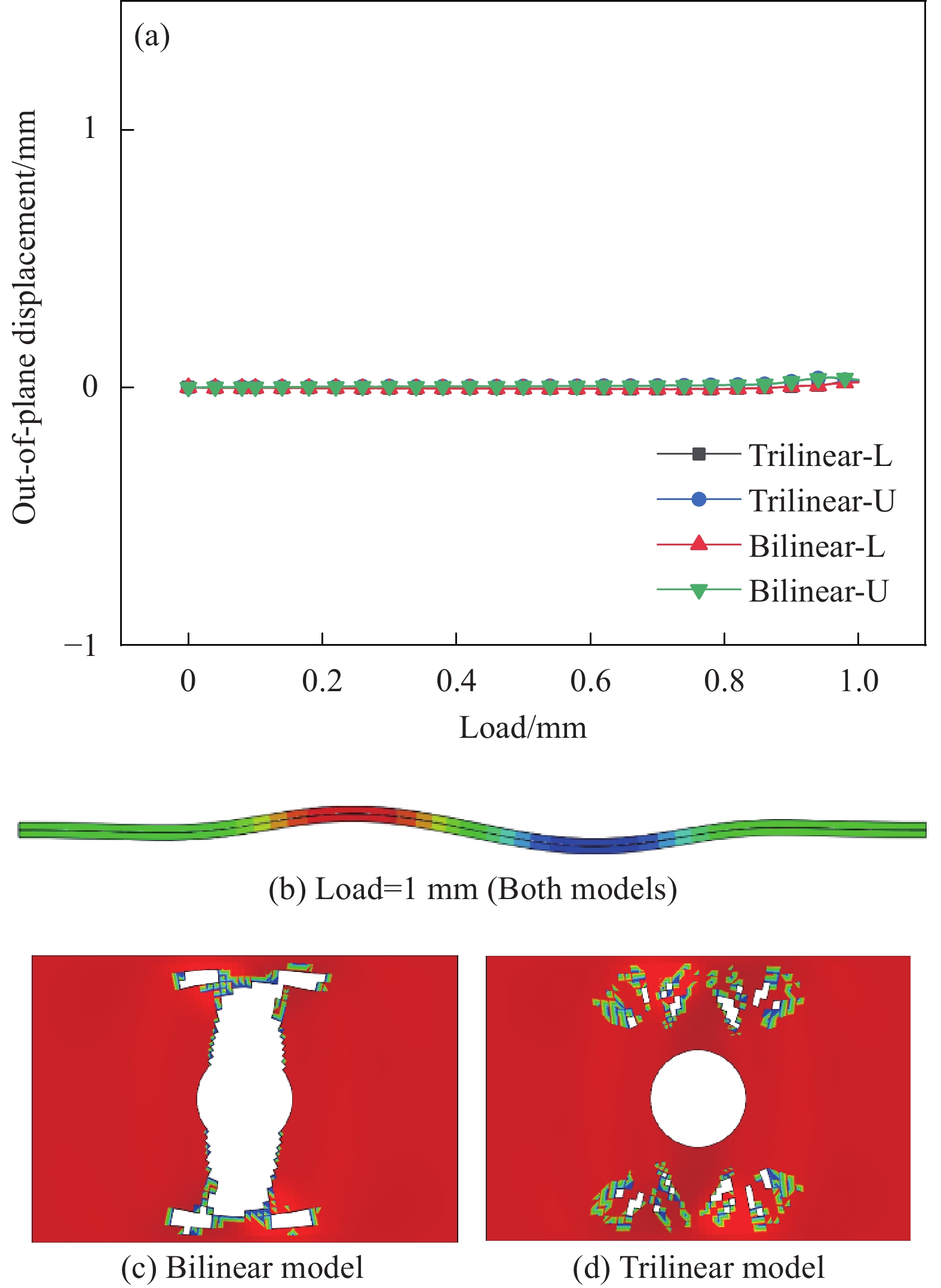
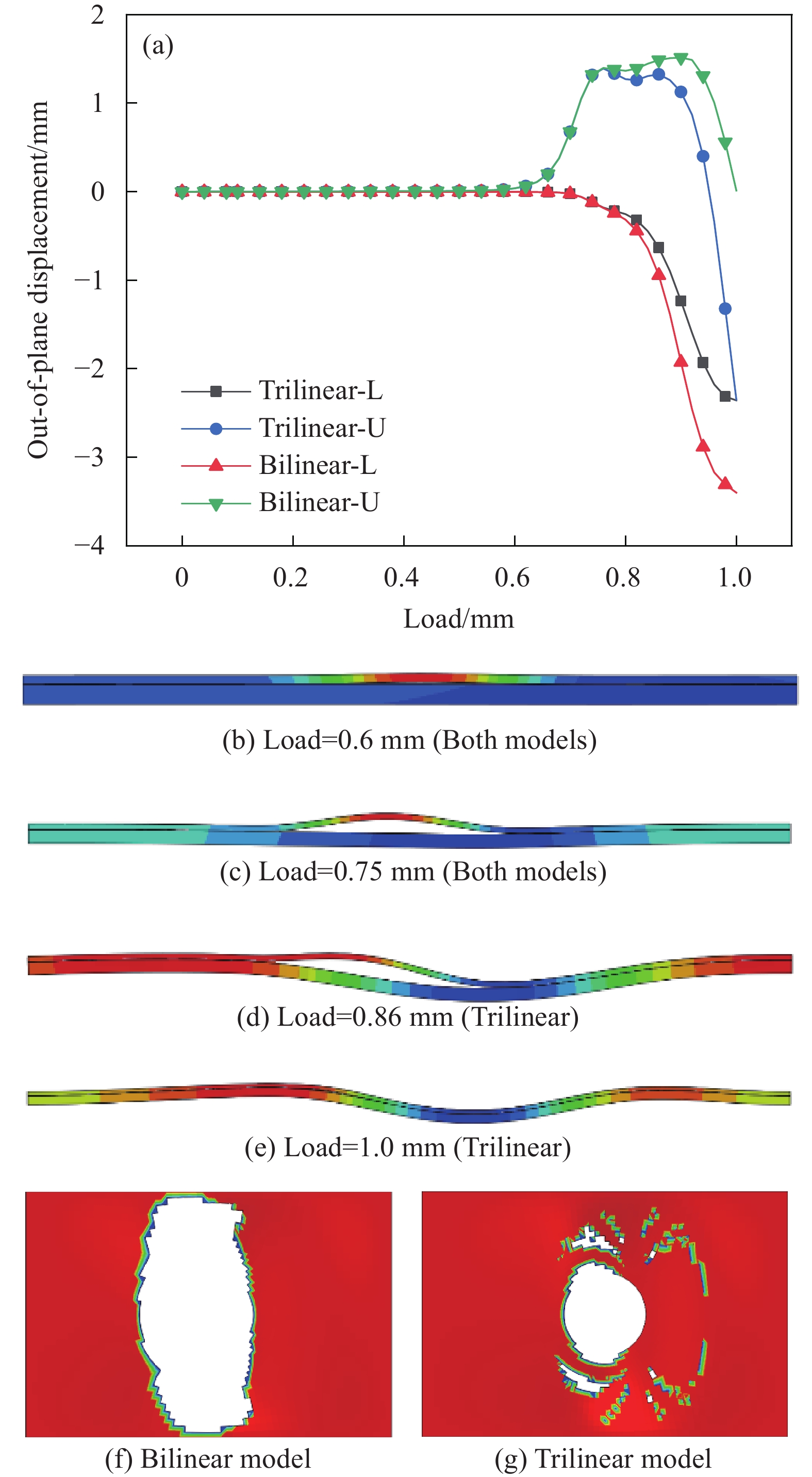
图 7 分层深度 D/H = 0.1的T700/TDE85层合板分层扩展及屈曲:(a) 面外位移-载荷曲线;((b), (c)) 不同载荷下两种模型的屈曲模式;((d), (e)) 不同模型的分层扩展预测
Figure 7. Delamination growth and buckling for normalized delamination depth D/H = 0.1 of T700/TDE85 laminates: (a) Out-of-plane deflection vs. loading displacement; ((b), (c)) Buckling modes of two models under different loads; ((d), (e)) Delamination propagation predicted by different model
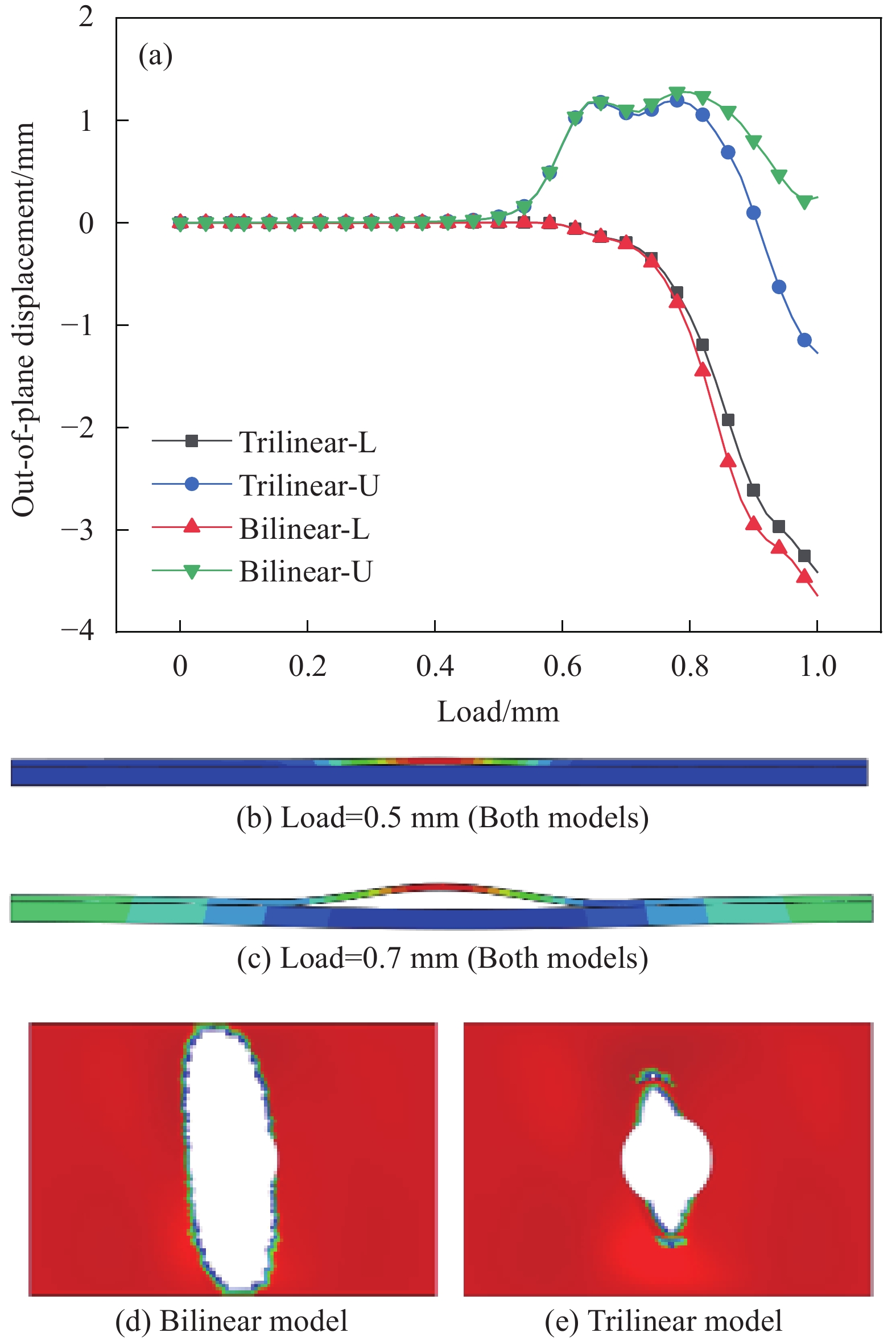
图 11 分层深度D/H = 0.5的T700/TDE85层合板分层扩展及屈曲:(a) 面外位移-载荷曲线;(b) 两种模型的屈曲模式;((c), (d)) 不同模型的分层扩展预测
Figure 11. Delamination growth and buckling for normalized delamination depth D/H = 0.5 of T700/TDE85 laminates: (a) Out-of-plane deflection vs. loading displacement; (b) Buckling mode of two models; ((c), (d)) Delamination propagation predicted by different model
图 8 分层深度D/H=0.25的T700/TDE85层合板分层扩展及屈曲:(a) 面外位移-载荷曲线;((b), (c)) 不同载荷下两种模型的屈曲模式;((d), (e)) 不同模型的分层扩展预测
Figure 8. Delamination growth and buckling for normalized delamination depth D/H=0.25 of T700/TDE85 laminates: (a) Out-of-plane deflection vs. loading displacement; ((b), (c)) Buckling modes of two models under different loads; ((d), (e)) Delamination propagation predicted by different model
图 9 分层深度D/H=0.3的T700/TDE85层合板分层扩展及屈曲:(a) 面外位移-载荷曲线;((b), (c), (d), (e)) 不同载荷下两种模型的屈曲模式;((f), (g)) 不同模型的分层扩展预测
Figure 9. Delamination growth and buckling for normalized delamination depth D/H=0.3 of T700/TDE85 laminates: (a) Out-of-plane deflection vs. loading displacement; ((b), (c), (d), (e)) Buckling modes of two models under different loads; ((f), (g)) Delamination propagation predicted by different model
图 10 分层深度D/H = 0.35的T700/TDE85层合板分层屈曲:(a) 面外位移-载荷曲线;(b) 两种模型的屈曲模式;((c), (d)) 不同模型的分层扩展预测
Figure 10. Delamination growth and buckling for normalized delamination depth D/H = 0.35 of T700/TDE85 laminates: (a) Out-of-plane deflection vs. loading displacement; (b) Buckling mode of two models; ((c), (d)) Delamination propagation predicted by different model
表 1 T700/TDE85单向板力学性能参数[35]
Table 1 Mechanical parameters of T700/TDE85 unidirectional laminates[35]
E11/MPa E22/MPa E33/MPa G12/MPa G13/MPa G23/MPa ν12 ν13 ν23 138000 10160 10160 5860 5860 4790 0.28 0.3 0.3 Notes: Eij—Young’s modulus; Gij—Shear modulus; vij—Poisson’s ratio, where subscripts i, j denote the principal material axes. K11/(N·mm−3) K22/(N·mm−3) K33/(N·mm−3) Nmax/MPa Smax/MPa Tmax/MPa GIC/(N·mm−1) GIIC/(N·mm−1) GIIIC/(N·mm−1) α 106 106 106 5 20 20 0.276 0.8 0.8 2 Notes: Kij—Interface stiffness; Nmax, Smax, Tmax—Interfacial strength in longitudinal and transverse directions, respectively; GiC—Fracture toughness; α—Power exponent factor. 表 3 三线性内聚力模型界面参数
Table 3 Interface parameters of the trilinear cohesive zone model
K11/(N·mm−3) K22/(N·mm−3) K33/(N·mm−3) Nmax/MPa Smax/MPa Tmax/MPa GIC/(N·mm−1) GIIC/(N·mm−1) GIIIC/(N·mm−1) α σb δb 106 106 106 5.25 21 21 0.359 1.04 1.04 2 0.2 0.11 Notes: σb—Maximum bridging stress; δb—Initial displacement of bridge fiber damage. -
[1] 赵丽滨, 龚愉, 张建宇. 纤维增强复合材料层合板分层扩展行为研究进展[J]. 航空学报, 2019, 40(1):171-199. ZHAO Libing, GONG Yu, ZHANG Jianyu. A survey on delamination growth behavior in fiber reinforced compo-site laminates[J]. Acta Aeronautica et Astronautica Sinica,2019,40(1):171-199(in Chinese).
[2] 王雪明, 谢富原, 李敏, 等. 热压罐成型复合材料构件分层缺陷影响因素分析[C]// 杜善义. 第十五届全国复合材料学术会议论文集(上册). 国防工业出版社, 2008: 537-541. WANG Xueming, XIE Fuyuan, LI Ming, et al. Factor analy-sis of delamination in composite components porduced by autoclave process[C]// DU Shanyi. Proceedings of the 15th national conference on composite materials (Volume I). National Defense Industry Press, 2008: 537-541(in Chinese).
[3] FOOTE R M L, MAI Y W, COTTERELL B. Crack growth resistance curves in strain-softening materials[J]. Journal of the Mechanics & Physics of Solids,1986,34(6):593-607.
[4] SMITH E. Displacement control crack-growth instability in an elastic-softening material[J]. Journal of Materials Science,1994,29(1):276-280. DOI: 10.1007/BF00356604
[5] CARPINTERI A, CADAMURO E, VENTURA G. Fiber-reinforced concrete in flexure: A cohesive/overlapping crack model application[J]. Materials and Structures,2015,48(1/2):235-247. DOI: 10.1617/s11527-013-0179-1
[6] STEPHEN S J, GETTU R, FERREIRA L E T, et al. Assessment of the toughness of fibre-reinforced concrete using the R-curve approach[J]. Sādhanā,2018,43(3):1-6.
[7] LEI W, HUA Z, LINGYU B, et al. Effect of fiber hybridization, strain rate and W/C ratio on the impact behavior of hybrid FRC[J]. Materials,2019,12(17):2780. DOI: 10.3390/ma12172780
[8] GONG Y, ZHANG B R, HALLETT S. Delamination migration in multidirectional composite laminates under mode I quasi-static and fatigue loading[J]. Composite Structures,2018,189:160-176. DOI: 10.1016/j.compstruct.2018.01.074
[9] GONG Y, ZHANG B, MUKHOPADHYAY S, et al. Experimental study on delamination migration in multidirec-tional laminates under mode II static and fatigue loading, with comparison to mode I[J]. Composite Structures,2018,201:683-698. DOI: 10.1016/j.compstruct.2018.06.081
[10] BRUNNER A J, BLACKMAN B R K, DAVIES P. A status report on delamination resistance testing of polymer-matrix composites[J]. Engineering Fracture Mechanics,2007,75(9):2779-2794.
[11] BRUNNER A J, BLACKMAN B R K. Delamination fracture in cross-ply laminates: What can be learned from experiment?[J]. European Structural Integrity Society,2003,32:433-444.
[12] DE MORAIS A B, DE MOURA M F, MARQUES A T, et al. Mode-I interlaminar fracture of carbon/epoxy cross-ply composites[J]. Composites Science and Technology,2002,62(5):679-686. DOI: 10.1016/S0266-3538(01)00223-8
[13] GONG Y, CHEN X J, LI W C, et al. Delamination in carbon fiber epoxy DCB laminates with different stacking sequences: R-curve behavior and bridging traction-separation relation[J]. Composite Structures,2021,262:113605. DOI: 10.1016/j.compstruct.2021.113605
[14] DE MOURA M F S F, CAMPILHO R D S G, AMARO A M, et al. Interlaminar and intralaminar fracture characterization of composites under mode I loading[J]. Composite Structures,2010,92(1):144-149. DOI: 10.1016/j.compstruct.2009.07.012
[15] PEREIRA A B, DE MORAIS A B. Mode I interlaminar fracture of carbon/epoxy multidirectional laminates[J]. Composites Science and Technology,2004,64(13):2261-2270.
[16] GONG Y, HOU Y, ZHAO L, et al. A modified mode I cohe-sive zone model for the delamination growth in DCB lami-nates with the effect of fiber bridging[J]. International Journal of Mechanical Sciences,2020,176:105514. DOI: 10.1016/j.ijmecsci.2020.105514
[17] HU P, PULUNGAN D, TAO R, et al. An experimental study on the influence of intralaminar damage on interlaminar delamination properties of laminated composites[J]. Composites Part A,2020,131:105783. DOI: 10.1016/j.compositesa.2020.105783
[18] LACHAUD F, PAROISSIEN E, MICHEL L. Validation of a simplified analysis for the simulation of delamination of CFRP composite laminated materials under pure mode I[J]. Composite Structures,2020,237:111897. DOI: 10.1016/j.compstruct.2020.111897
[19] CHOI N S. Delamination fracture of multidirectional carbon-fiber/epoxy composites under mode I, mode II and mixed-mode I/II loading[J]. Journal of Composite Materials,1999,33(1):73-100. DOI: 10.1177/002199839903300105
[20] PEREIRA A B, DE MORAIS A B, MARQUES A T, et al. Mode II interlaminar fracture of carbon/epoxy multidirectional laminates[J]. Composites Science and Technology,2003,64(10):1653-1659.
[21] GONG Y, ZHAO L B, ZHANG J Y, et al. Delamination propagation criterion including the effect of fiber bridging for mixed-mode I/II delamination in CFRP multi-directional laminates[J]. Composites Science and Technology,2017,151:302-309. DOI: 10.1016/j.compscitech.2017.09.002
[22] GONG Y, ZHAO L B, ZHANG B, et al. R-curve behaviour of the mixed-mode I/II delamination in carbon/epoxy lami-nates with unidirectional and multidirectional interfaces[J]. Composite Structures,2019,223:110949. DOI: 10.1016/j.compstruct.2019.110949
[23] BAE H, KANG M, WOO K, et al. Test and analysis of modes I, II and mixed-mode I/II delamination for carbon/epoxy composite laminates[J]. International Journal of Aeronau-tical and Space Sciences,2019,20(3):636-652. DOI: 10.1007/s42405-019-00170-9
[24] XU X P, NEEDLEMAN A. Void nucleation by inclusion debonding in a crystal matrix[J]. Modelling & Simulation in Materials Science & Engineering,1999,1(2):111-132.
[25] VIGGO T, JOHN W H. The relation between crack growth resistance and fracture process parameters in elastic-plastic solids[J]. Journal of the Mechanics and Physics of Solids,1992,40(6):1377-1397. DOI: 10.1016/0022-5096(92)90020-3
[26] MANGALGIRI P D, JOHNSON W S. Investigation of fiber bridging in double cantilever beam specimens[J]. Journal of Composites, Technology and Research,1987,9(1):10. DOI: 10.1520/CTR10421J
[27] YAO L, CUI H, ALDERLIESTEN R C, et al. Thickness effects on fibre-bridged fatigue delamination growth in compo-sites[J]. Composites Part A,2018,110:21-28. DOI: 10.1016/j.compositesa.2018.04.015
[28] LIU W L, CHEN P H. Theoretical analysis and experi-mental investigation of the occurrence of fiber bridging in unidirectional laminates under mode I loading[J]. Composite Structures,2021,257:113383. DOI: 10.1016/j.compstruct.2020.113383
[29] DÁVILA C G A, ROSE C P, CAMANHO P. A procedure for superposing linear cohesive laws to represent multiple damage mechanisms in the fracture of composites[J]. International Journal of Fracture,2009,158(2):211-223. DOI: 10.1007/s10704-009-9366-z
[30] AIROLDI A, DÁVILA C G. Identification of material parameters for modelling delamination in the presence of fibre bridging[J]. Composite Structures,2012,94(11):3240-3249. DOI: 10.1016/j.compstruct.2012.05.014
[31] 侯怡鑫. 含纤维桥接的复合材料层合板分层扩展内聚力模型[D]. 重庆: 重庆大学, 2018. HOU Yixin. Cohesive model for delamination in composite multidirectional laminates with fiber bridging[D]. Chongqing: Chongqing University, 2018(in Chinese).
[32] SHOKRIEH M M, RAJABPOUR-SHIRAZI H, HEIDARI-RARANI M, et al. Simulation of mode I delamination propagation in multidirectional composites with R-curve effects using VCCT method[J]. Computational Materials Science,2012,65:66-73. DOI: 10.1016/j.commatsci.2012.06.025
[33] FARMAND-ASHTIANI E, ALANIS D, CUGNONI J, et al. Delamination in cross-ply laminates: Identification of traction separation relations and cohesive zone modeling[J]. Composites Science and Technology,2015,119:85-92. DOI: 10.1016/j.compscitech.2015.09.025
[34] LI S, NIE J, QIAN J, et al. Initial post-buckling and growth of a circular delamination bridged by nonlinear fibers[J]. Journal of Applied Mechanics,2000,67(4):777-784. DOI: 10.1115/1.1313534
[35] 张璐. 含分层缺陷复合材料层合板分层扩展行为与数值模拟研究[D]. 哈尔滨: 哈尔滨工业大学, 2012. ZHANG Lu. Numerical analysis and experimental study on propagation behavior of laminated composite plates with embedded delamination[D]. Harbin: Harbin Institute of Technology, 2012(in Chinese).
[36] 张东哲, 林智育, 林仁邦, 等. 含分层复合材料结构压缩强度研究[J]. 复合材料科学与工程, 2020(12):64-73. DOI: 10.3969/j.issn.1003-0999.2020.12.011 ZHANG Dongzhe, LIN Zhiyu, LIN Renbang, et al. Study of compressive strength of composite structure with delami-nation[J]. Composites Science and Engineering,2020(12):64-73(in Chinese). DOI: 10.3969/j.issn.1003-0999.2020.12.011
[37] 熊颖, 薛江红, 陈叔华, 等. 考虑界面接触效应的复合材料层合板分层屈曲的三维有限元分析[J]. 机械强度, 2019, 41(2):377-382. XIONG Ying, XUE Jianghong, CHEN Shuhua, et al. Three-dimensional finite element analysis of delamination buckling of composite laminates with contact effect at the interfaces of delamination[J]. Journal of Mechanical Strength,2019,41(2):377-382(in Chinese).
[38] SENTHIL K, AROCKIARAJAN A, PALANINATHAN R, et al. Defects in composite structures: Its effects and prediction methods-A comprehensive review[J]. Composite Structures,2013,106:139-149. DOI: 10.1016/j.compstruct.2013.06.008
[39] WANG K, ZHAO L, HONG H, et al. An analytical model for evaluating the buckling, delamination propagation, and failure behaviors of delaminated composites under uni-axial compression[J]. Composite Structures,2019,223:110937. DOI: 10.1016/j.compstruct.2019.110937
[40] HWANG S F, LIU G H. Buckling behavior of composite laminates with multiple delaminations under uniaxial compression[J]. Composite Structures,2001,53(2):235-243. DOI: 10.1016/S0263-8223(01)00007-1
-
期刊类型引用(1)
1. 马封安,赵广慧,田程,贾宇喆,刘涛. 缺陷对连续纤维增强复合材料力学性能影响的研究进展. 中国塑料. 2025(01): 104-111 .  百度学术
百度学术
其他类型引用(5)
-


 下载:
下载:


