

Experimental study on the shear performance of concrete beams reinforced with new type closed winding GFRP stirrups
-
摘要: 对采用新型封闭缠绕式玻璃纤维增强树脂复合材料(GFRP)箍筋的混凝土梁进行了三点加载试验,考察了箍筋形式、纵筋配筋率、剪跨比、箍筋间距对配置新型封闭缠绕式GFRP箍筋混凝土梁受剪性能的影响规律。试验结果表明,新型封闭缠绕式GFRP箍筋的弯曲段强度与平直段受拉强度之比达到0.81,是拉挤成型箍筋的2.07倍。剪跨比和箍筋间距相同时,新型封闭缠绕式GFRP箍筋混凝土梁的受剪性能更好,其材料利用效率显著高于拉挤成型箍筋。梁的抗剪承载力随纵筋配筋率增加的提高幅度不大,但梁的延性有较明显改善。当箍筋间距为75 mm,新型封闭缠绕式GFRP箍筋的应变显著增大,同时对剪压区混凝土产生一定的约束作用,提升了受剪承载力。采用中国(GB 50608—2020)、美国(ACI 440.1R-15)、加拿大(CSA S806-12)、英国(BISE—1999)和日本(JSCE—1997)五种纤维增强树脂复合材料(FRP)筋混凝土结构设计规范计算的受剪承载力显著低于试验值,建议适当提高新型封闭缠绕式GFRP箍筋的断裂应变限值。Abstract: This experimental study conducted a three-point loading test of concrete beams reinforced with a new type closed winding glass fiber-reinforced polymer (GFRP) stirrups, the effects of the form of stirrups, longitudinal reinforcement ratio, shear-span ratio and stirrups spacing on the shear behavior of concrete beams reinforced with new type closed winding GFRP stirrups were investigated. The test results indicate that the ratio of bend strength over tensile strength at the straight portion of new type closed winding GFRP stirrups is 0.81, which is 2.07 times higher than that of pultruded stirrups. When the shear-span ratio and the stirrups spacing are identical, beams with new type closed winding GFRP stirrups show improved shear performance compared with beams with pultruded stirrups. The increase in longitudinal reinforcement ratio has a minor effect on the shear capacity but could significantly improve the ductility of beams. When the spacing of the stirrups is 75 mm, new type closed winding GFRP stirrups produce greater stirrups strain and strongly confine the shear-compression zone of the concrete beam, which significantly enhances the shear capacity. The calculated shear capacities according to five fiber reinforced resin composite (FRP) reinforced concrete design codes of Chinese code (GB 50608—2020), American code (ACI 440.1R-15), Canadian code (CSA S806-12), British code (BISE—1999) and Japanese code (JSCE—1997) are significantly lower than the experimental results. It is suggested that the strain limit in design codes should be appropriately increased.
-
Keywords:
- shear behavior /
- concrete beams /
- FRP reinforcement /
- shear-span ratio /
- stirrups
-
对处于侵蚀性环境的钢筋混凝土结构,由于钢材锈蚀导致的结构性能劣化乃至过早破坏是普遍面临的重要问题。为克服这一问题,部分学者提出采用轻质高强和耐腐蚀性能优越的纤维增强树脂复合材料(FRP)筋代替钢筋以解决钢筋锈蚀问题,进而提高混凝土结构的耐久性性能。目前,FRP筋已逐步应用于地铁、码头、桥梁等实际工程结构,具有广泛的应用前景[1-6]。
传统FRP筋主要通过拉挤成型工艺生产。FRP箍筋则是在树脂固化之前,将拉挤成型的圆形截面FRP筋,弯折成有箍肢搭接的箍圈。拉挤成型箍筋依靠搭接区域的箍肢与混凝土的粘结来传递拉应力。有试验表明,混凝土构件破坏时,传统拉挤成型FRP箍筋虽未断裂,但其搭接段发生了粘结滑移破坏[7-8]。与此同时,FRP筋弯折过程也会造成弯曲段内侧纤维蜷曲,受拉时外侧纤维先于内侧纤维受力造成应力集中,进而导致FRP箍筋弯曲段受拉强度降低。FRP箍筋弯曲段受拉强度仅为其平直段受拉强度的30%~60%[9-13]。FRP箍筋的弯曲段抗拉强度的降低,也导致FRP筋混凝土梁受剪时的常见破坏模式为FRP箍筋在弯曲段断裂[14-17]。若斜裂缝恰好经过FRP箍筋的弯曲段,则其受拉强度还可能进一步降低[18]。因此,为避免FRP箍筋的破坏,各国FRP筋混凝土结构设计规范也都有箍筋中的应力小于其弯曲段强度的规定[19-23]。这也意味着传统拉挤成型FRP箍筋,在结构达到承载力极限状态时应力水平较低,材料抗拉强度高的性能未得到充分利用。
为克服拉挤成型FRP箍筋材料利用效率低的问题,Dong等[24]基于缠绕工艺提出了新型封闭缠绕式玻璃纤维增强树脂复合材料(GFRP)箍筋。其生产工艺主要是将浸润树脂的连续GFRP逐层缠绕在旋转的钢模具上,固化脱模后形成管材;再将管材按照一定宽度切割得到新型封闭缠绕式GFRP箍筋。新型封闭缠绕式GFRP箍筋弯曲段的纤维蜷曲现象得到了显著缓解,故箍筋弯曲段强度显著提升;而且新型封闭缠绕式GFRP箍筋连续封闭不存在搭接段,故也不会发生粘结滑移破坏。针对新型封闭缠绕式GFRP箍筋约束混凝土柱的轴压试验表明:新型封闭缠绕式GFRP箍筋对核心区混凝土约束作用较强,柱的延性得到显著提升,新型封闭缠绕式GFRP箍筋约束混凝土柱的极限受压应变是拉挤成型箍筋约束混凝土柱的3.42倍[25]。
目前,对新型封闭缠绕式GFRP箍筋混凝土构件抗剪性能的研究还处于空白。故本文对新型封闭缠绕式GFRP箍筋混凝土梁进行了三点加载试验,考察新型封闭缠绕式GFRP箍筋受剪时的破坏模式和利用效率,明确箍筋形式、剪跨比、箍筋间距和纵筋配筋率等参数对配置新型FRP箍筋混凝土受剪性能的影响规律;并对已有规范中FRP筋混凝土构件抗剪承载力计算公式计算结果与试验进行了对比分析。
1. 试 验
1.1 试验设计
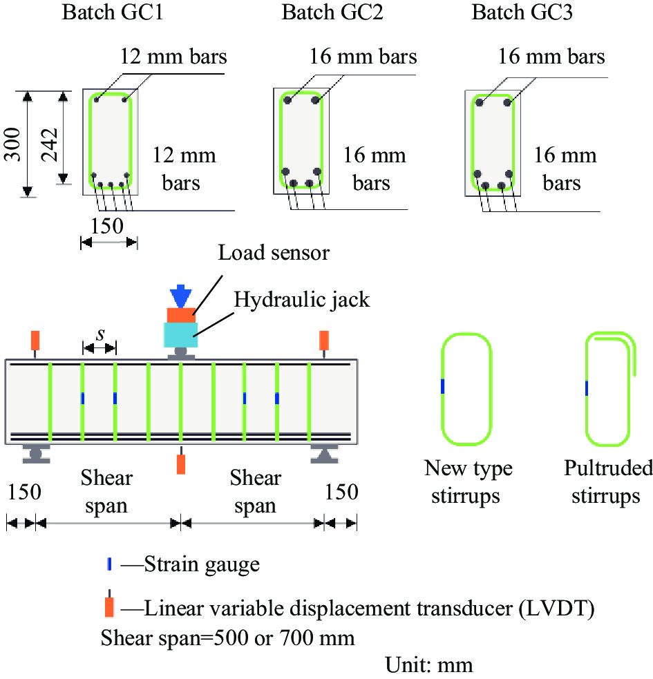
共设计制作了14根截面高度为300 mm,宽度为150 mm的FRP筋混凝土梁。根据剪跨比和纵筋配筋率的不同,试件共分为3组(GC1、GC2和GC3)。GC1组包括4个配置新型封闭缠绕式GFRP箍筋的试件和1个设置传统拉挤成型箍筋的对比试件,试件剪跨比均约为2.1,纵筋配筋率为1.54%;GC2组共有4个配置新型封闭缠绕式GFRP箍筋的试件,剪跨比与GC1组试件保持一致,而纵筋配筋率为2.21%;GC3组共5个试件,其中4个试件采用新型封闭缠绕式GFRP箍筋,1个对比试件配置拉挤成型箍筋,试件剪跨比均为2.9,纵筋配筋率与GC2组试件相同,为2.21%。在每组试件中,采用新型封闭缠绕式GFRP箍筋试件的箍筋间距分别为75 mm、100 mm、125 mm和150 mm,配置拉挤成型箍筋的试件的箍筋间距为100 mm。试验所使用的新型封闭缠绕式GFRP箍筋截面宽度为9 mm,截面厚度为3 mm。试验所使用的拉挤成型FRP箍筋的直径为8 mm,箍肢搭接位置位于角部。两种箍筋的内皮尺寸相同,均为宽100 mm,高234 mm,弯曲段的弯折半径为30 mm。试件详细工况见表1。
表 1 试验工况Table 1. Test matrixSpecimen Stirrups type s/mm ρ/% ρv/% λ GC1-P100 Pultruded 100 1.54 0.67 2.1 GC1-W75 New type 75 1.54 0.48 2.1 GC1-W100 New type 100 1.54 0.36 2.1 GC1-W125 New type 125 1.54 0.29 2.1 GC1-W150 New type 150 1.54 0.24 2.1 GC2-W75 New type 75 2.21 0.48 2.1 GC2-W100 New type 100 2.21 0.36 2.1 GC2-W125 New type 125 2.21 0.29 2.1 GC2-W150 New type 150 2.21 0.24 2.1 GC3-P100 Pultruded 100 2.21 0.67 2.9 GC3-W75 New type 75 2.21 0.48 2.9 GC3-W100 New type 100 2.21 0.36 2.9 GC3-W125 New type 125 2.21 0.29 2.9 GC3-W150 New type 150 2.21 0.24 2.9 Notes: ρ—Longitudinal reinforcement ratio; ρv—Shear reinforcement ratio; λ—Shear-span ratio; GC—Glass fiber-reinforced polymer (GFRP) stirrups reinforced concrete beams; P—Pultruded GFRP stirrups; W—Closed winding stirrups; s—Stirrups spacing. 三点试验的加载与测量装置如图1所示。跨中集中力采用600 kN千斤顶加载,跨中与支座处变形由位移计量测。每个试件的剪跨段选取4个箍筋(编号S1~S4)粘贴应变片,量测箍筋拉应变。加载方式采用力控制,试件开裂前10 kN一级,开裂后20 kN一级加载,直至破坏。
![]() 图 1 试件截面与加载测量装置示意图Figure 1. Schematic drawing of cross-sectional details, test set-up and instrumentation of beam test
图 1 试件截面与加载测量装置示意图Figure 1. Schematic drawing of cross-sectional details, test set-up and instrumentation of beam test1.2 材料力学性能
试验制作了直径为150 mm、高为300 mm的标准圆柱体试件,其轴心抗压强度平均值为42 MPa。试验所采用的GFRP纵筋与拉挤成型GFRP箍筋的纤维体积含量均约为60vol%。使用未经弯曲的直径为8 mm的拉挤成型纵筋,依据纤维增强复合材料筋基本力学性能试验方法(GB/T 30022—2013)[26]量测其平直段受拉性能,如图2(a)所示。将新型封闭缠绕式GFRP箍筋切割后得到长度为174 mm的平直段,依据ASTM D3039/3039 M-00[27]规定的测试方法测试其受拉性能,如图2(b)所示。由于混凝土梁中所使用的箍筋尺寸较小,制作了内皮尺寸为250 mm×550 mm的新型封闭缠绕式GFRP箍筋与拉挤成型箍筋测试其弯曲段抗拉强度。两类箍筋的弯曲段抗拉强度均依据ACI 440.3 R-12[28]建议的测试方法量测,如图2(c)所示。首先将FRP箍筋的弯曲段分别浇筑在两个分离的混凝土块体中;然后在两混凝土块体间放置千斤顶施加荷载,直至箍筋弯曲段断裂。实测得到的各类FRP筋材的力学性能见表2。可知,拉挤成型箍筋的弯曲段与平直段受拉强度之比仅为0.39,而新型封闭缠绕式GFRP箍筋为0.81,新型封闭缠绕FRP箍筋的弯曲段强度显著提高。ACI 440.1 R-15[20]建议按照下式计算拉挤成型箍筋的弯曲段抗拉强度与平直段抗拉强度之比:
ffbffu = 0.05rbdb + 0.3 (1) ![]() 图 2 纤维增强树脂复合材料(FRP)筋材的材料性能测试Figure 2. Material test of fiber reinforced polymer (FRP) reinforcement表 2 FRP筋材力学性能参数Table 2. Mechanical properties of FRP reinforcements
图 2 纤维增强树脂复合材料(FRP)筋材的材料性能测试Figure 2. Material test of fiber reinforced polymer (FRP) reinforcement表 2 FRP筋材力学性能参数Table 2. Mechanical properties of FRP reinforcementsMaterial GFRP bar Pultruded stirrups New type stirrups d/mm or w×t/mm2 16 8 9×3 A/mm2 201 50 27 E/MPa 47.2 50.2 55.0 ffu/MPa 889 1059 1096 εfu/% 1.88 2.12 1.99 ffb/MPa − 415 892 ffb/ffu − 0.39 0.81 Notes: d—Diameter of pultruded GFRP bar or stirrups; w and t—Width and thickness of new type stirrups; A—Cross-sectional area of reinforcement; E—Elastic modulus; ffu—Tensile strength of the straight portion of reinforcements; εfu—Ultimate strain at the straight portion; ffb—Bend corner strength of stirrups. 其中:ffb为箍筋弯曲段受拉强度;ffu为箍筋平直段受拉强度;rb为箍筋的弯曲段半径;db为箍筋直径。依据上式计算的拉挤成型箍筋弯曲段受拉强度与平直段受拉强度之比为0.48,是试验值的1.23倍。
2. 结果与讨论
2.1 GFRP筋混凝土梁破坏过程与破坏模式
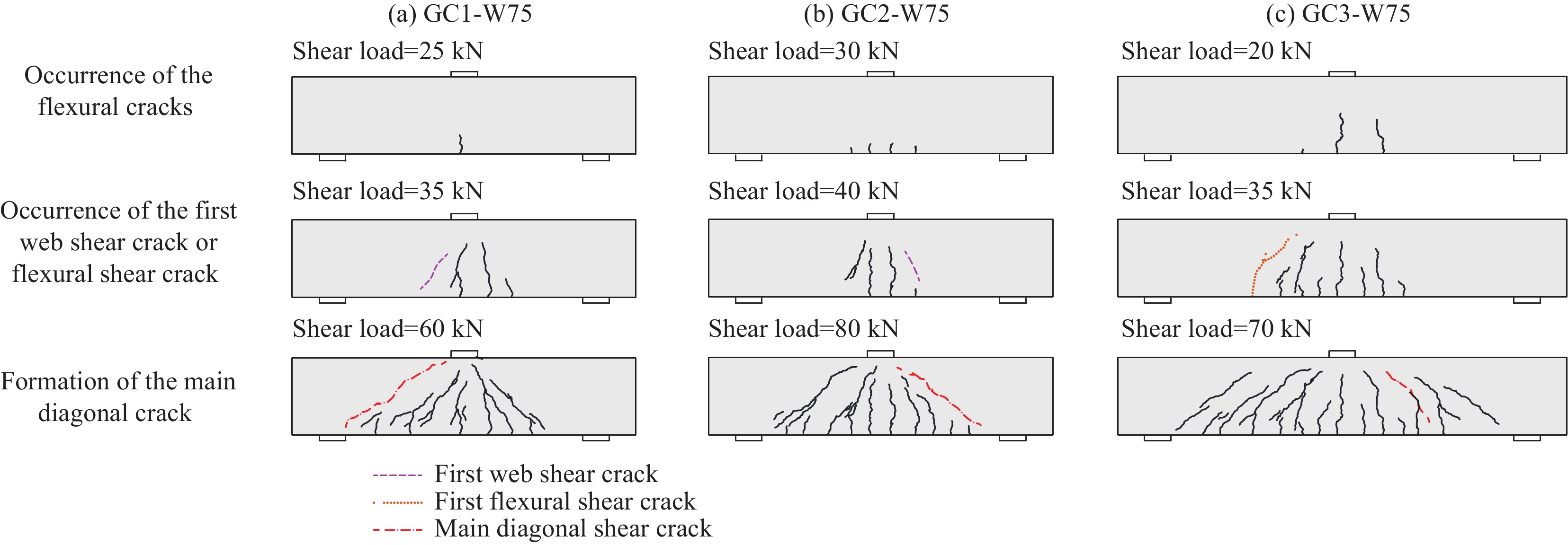
图3以试件GC1-W75、GC2-W75与GC3-W75为例,给出了各组试件的典型裂缝开展过程。剪跨比为2.1的GC1和GC2组试件的裂缝发展过程基本相同。加载初期,梁跨中区域首先出现竖向弯曲裂缝;随着荷载的增加,剪跨段约梁高1/3处出现腹剪斜裂缝,并逐步向梁底支座处与梁顶加载点处延伸;诸条斜裂缝中的一条最终形成临界斜裂缝,其形态近似为直线。剪跨比为2.9的GC3组试件,在跨中区域产生弯曲裂缝之后,剪跨段内随之产生弯曲裂缝并继续向上发展,到达约梁高度1/3时倾斜发展形成弯剪裂缝;斜裂缝进入梁受压区后裂缝倾斜角度减小,最终破坏时形成近似双折线形的临界斜裂缝。
![]() 图 3 试件GC1-W75 (a)、GC2-W75 (b) 与GC3-W75 (c) 的裂缝开展过程Figure 3. Crack propagation process of specimen GC1-W75 (a), GC2-W75 (b) and GC3-W75 (c)
图 3 试件GC1-W75 (a)、GC2-W75 (b) 与GC3-W75 (c) 的裂缝开展过程Figure 3. Crack propagation process of specimen GC1-W75 (a), GC2-W75 (b) and GC3-W75 (c)图4给出了各试件的破坏模式。剪跨比为2.1的GC1和GC2组试件最终均表现为剪压破坏模式。GC1组试件中,除箍筋间距较小的GC1-W75试件的新型封闭缠绕式GFRP箍筋在与斜裂缝相交处发生了断裂,同时伴有混凝土保护层的碎裂与剥落,其他试件的箍筋均保持完好。GC2组试件由于纵筋配筋率的增加,GC2-W75和GC2-W100试件都发生了箍筋的断裂,GC2-W125的箍筋也发生了纤维间的劈裂;同时混凝土剥落的面积也比GC1组更大;仅箍筋间距较大的GC2-W150试件的箍筋保持完好。
剪跨比为2.9的GC3组试件中,GC3-W100发生了弯曲破坏,破坏时加载点附近的梁顶混凝土被压碎脱落,箍筋完好,但其临界斜裂缝较宽;而配置拉挤成型箍筋的GC3-P100试件为斜拉破坏,同时由于拉挤成型箍筋搭接区段发生了滑移,箍筋中的应力较低,试件破坏后箍筋保持完好。随着箍筋间距的增加,GC3-W125与GC3-W150试件发生斜拉破坏,破坏时临界斜裂缝顶端突然向梁顶发展,整条裂缝突然张开,新型封闭缠绕式GFRP箍筋也发生断裂。然而,箍筋间距最小的GC3-W75试件却也发生了由箍筋断裂引起的斜拉破坏;这是由于间距为75 mm时新型封闭缠绕式GFRP箍筋的净距仅为66 mm,此时箍筋对核心区混凝土可以提供一定的约束作用,提高了受压区混凝土的极限压应变,延缓了梁顶混凝土的压碎,增强了梁的抗弯承载力,因此梁最终由于箍筋的断裂而发生斜拉破坏。
![]() 图 4 GFRP筋混凝土梁的破坏模式Figure 4. Failure mode of concrete beams reinforced with GFRP reinforcementS1, S2, S3, S4—Stirrups with strain gauges attached
图 4 GFRP筋混凝土梁的破坏模式Figure 4. Failure mode of concrete beams reinforced with GFRP reinforcementS1, S2, S3, S4—Stirrups with strain gauges attached试验还发现,新型封闭缠绕式GFRP箍筋的断裂均发生在箍肢与斜裂缝相交的平直段处,而拉挤成型FRP箍筋的断裂主要发生在弯曲段。这表明,新型封闭缠绕式GFRP箍筋在提高弯曲段受拉强度的同时改变了箍筋断裂位置,其受拉强度利用效率得到了显著提升。
2.2 GFRP筋混凝土梁剪力-位移曲线与受剪承载力
各组试件的剪力-位移曲线如图5所示;试件的开裂后刚度、受剪承载力和对应的跨中位移等主要试验结果见表3。
2.2.1 箍筋形式的影响
当剪跨比和箍筋间距相同时,拉挤成型箍筋梁的配筋率虽较高,但是其受剪性能并不优于甚至低于配箍率较低的新型封闭缠绕式GFRP箍筋混凝土梁。如GC1-P100的配箍率约为GC1-W100的1.8倍,但GC1-P100的开裂后刚度略低于GC1-W100,二者的承载力也几乎相同;GC3-W100的开裂后刚度高于GC3-P100,且其受剪承载力也比后者高约16%。这是拉挤成型箍筋的搭接段发生了相对滑移,箍筋的强度并未得到充分利用所致。
![]() 图 5 GFRP筋混凝土梁剪力-跨中位移曲线Figure 5. Shear load-midspan deflection curves of concrete beams reinforced with GFRP reinforcement表 3 GFRP筋混凝土梁受剪试验结果Table 3. Shear test result of GFRP reinforced concrete beams
图 5 GFRP筋混凝土梁剪力-跨中位移曲线Figure 5. Shear load-midspan deflection curves of concrete beams reinforced with GFRP reinforcement表 3 GFRP筋混凝土梁受剪试验结果Table 3. Shear test result of GFRP reinforced concrete beamsBeam Vu/kN Δp/mm Δu/mm Ks/(kN·mm−1) εmax/% εavg/% εavg/εfu Stirrups ruptured
or notGC1-P100 139.6 10.28 11.75 26.8 1.01 0.60 0.28 No GC1-W75 151.4 13.02 13.02 33.8 1.36 0.94 0.47 Yes GC1-W100 140.6 10.25 10.25 30.3 0.95 0.73 0.37 No GC1-W125 131.6 9.51 9.51 28.8 0.89 0.67 0.34 No GC1-W150 135.7 10.82 10.82 30.8 1.11 0.62 0.31 No GC2-W75 168.4 15.93 15.93 46.4 1.54 1.23 0.62 Yes GC2-W100 137.4 8.42 10.31 45.8 − − − Yes GC2-W125 139.9 8.17 13.05 46.1 1.14 0.60 0.30 No GC2-W150 103.5 6.39 10.51 36.1 1.06 0.53 0.27 No GC3-P100 101.8 17.08 17.08 12.6 1.12 0.68 0.32 No GC3-W75 147.9 32.78 32.78 16.6 1.59 1.24 0.62 Yes GC3-W100 117.5 27.46 27.46 14.9 1.09 0.86 0.43 No GC3-W125 102.4 24.23 24.23 15.2 1.54 1.04 0.52 Yes GC3-W150 92.9 15.28 15.28 15.7 1.31 1.11 0.56 Yes Notes: Vu—Shear capacity; Δp—Midspan deflection at peak load; Δu—Midspan deflection at final failure (for the specimens failed at peak load, Δu is equal to the Δp); Ks—Stiffness after shear cracking, which was calculated as the slope of the line connecting the two points with loads of 40 kN and 90 kN respectively; εmax—Maximal stirrups strain at ultimate; εavg—Average stirrups strain at ultimate; εfu—Ultimate strain. The strain gauges of GC2-W100 were damaged prior to the failure. 2.2.2 剪跨比的影响
由图5(a)与图5(b)可知,当剪跨比相同时,GC1和GC2两组试件产生弯曲裂缝之后试件的刚度几乎没有退化,直至试件破坏。这是由于两组试件的剪跨比小于2.5,其传力机制以“拱机制”为主,混凝土对剪力的贡献较大,荷载可以直接通过混凝土压杆传递到支座处[29];试件的破坏由压杆顶部剪压区混凝土控制。当剪跨比增大到2.9时,GC3组试件的剪力-位移曲线近似为双折线,当试件的荷载增大至约90~110 kN,梁顶部的受压纵筋在与斜裂缝相交处断裂使荷载突然下降,随后荷载仍继续增大直至最终破坏。此时,荷载可以由简化为FRP筋拉杆与混凝土压杆组成的桁架模型传递[30],传力机制以“梁机制”为主;此时箍筋承担的剪力比例增大,混凝土承担的剪力显著减小[31];与GC1和GC2组试件相比,GC3组试件的受剪承载力、开裂后刚度均有所下降,跨中位移也显著增加。
2.2.3 箍筋间距的影响
对于剪跨比为2.1的试件,箍筋间距为100 mm、125 mm与150 mm试件的受剪承载力均在130~140 kN之间,此时配箍率较低,箍筋对承载力的贡献较小。随着箍筋间距减小至75 mm,试件的受剪承载力有所提高,特别是纵筋配筋率较大的GC2组试件。如GC1-W75的承载力比GC-W100和GC-W150分别提高了8%和12%,GC2-W75的承载力比GC2-W100和GC2-W150分别提高了23%和63%。对于剪跨比为2.9的试件,受剪承载力随着箍筋间距的增加而明显降低;箍筋间距由75 mm,增加到100 mm、125 mm和150 mm时,试件的受剪承载力分别降低了21%、31%和37%。
2.2.4 纵筋配筋率的影响
由图5(a)和图5(b)比较可知,在剪跨比相同时,由于GFRP筋的弹性模量较低,梁的抗剪承载力随纵筋配筋率增加的提高幅度不大,但GC2组梁的峰值位移有所减小,同时延性有较明显改善。GC1组试件在剪力到达峰值后试件随即破坏,承载力急剧下降;而GC2组试件在剪力达到峰值后,位移仍持续增大并表现出水平段或较缓的下降段。表3中列出了GC2组试件在最终破坏时的极限位移,比峰值点位移增大了约2~4 mm。GC2-W100与GC2-W125的极限位移甚至超过了GC1组试件的峰值位移。在位移显著增大的过程中,临界斜裂缝也快速变宽,造成了试件GC2-W100与试件GC2-W125箍筋的断裂与损伤。
2.3 GFRP箍筋应变
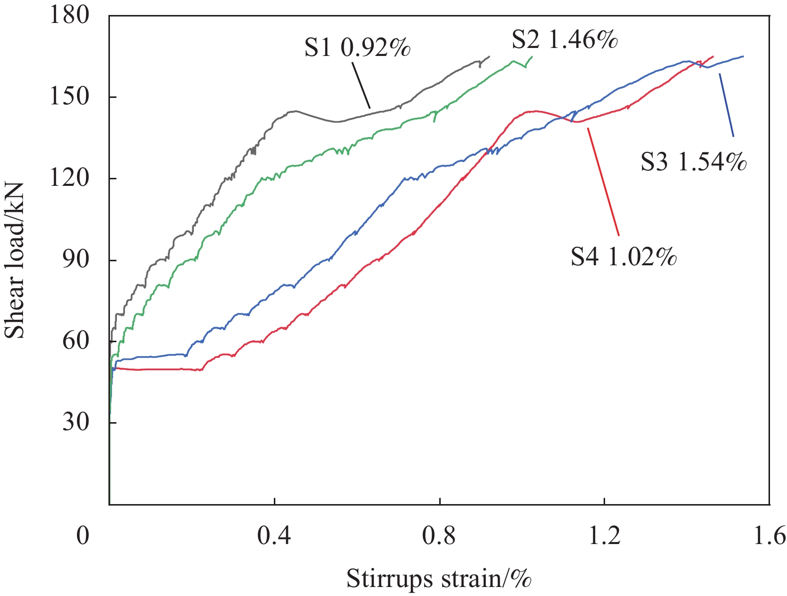
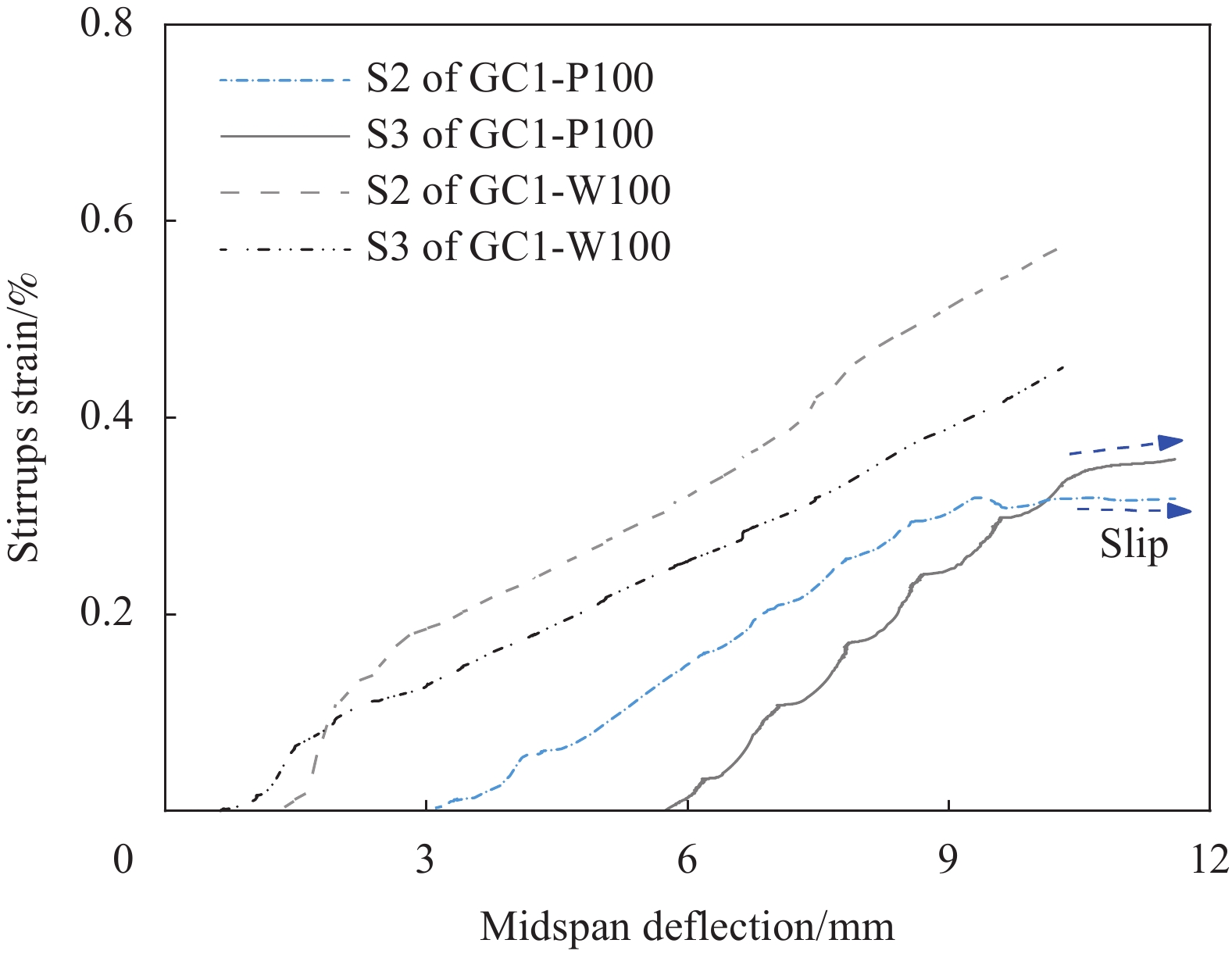
箍筋的应变响应可以真实反映加载过程中箍筋所受拉力的大小,以试件GC2-W75为例给出试件的典型剪力-箍筋应变曲线,如图6所示。可知,加载初期箍筋应变几乎为零,直到斜裂缝出现之后,箍筋才受拉力作用产生应变。随着斜裂缝的开展变宽,箍筋应变也逐步增长直到试件最终破坏;箍筋的应变大小与斜裂缝的相对位置有关,距离斜裂缝越近,应变片测得的箍筋应变越大。表3中总结了在承载力极限状态下各个试件的最大箍筋应变与平均应变,其中平均应变是试件中所有粘贴有应变片的箍筋的应变平均值。可知箍筋的平均应变约为最大应变的50%~85%;当剪跨比与箍筋间距相同时,新型封闭缠绕式GFRP箍筋的平均应变比拉挤成型箍筋的平均应变大20%以上,如试件GC1-W100的平均应变比GC1-P100大22%,GC3-W100的平均应变比GC3-P100大26%。图7所示为试件GC1-P100与GC1-W100的箍筋应变-跨中位移关系曲线,可得到相同规律;同时还可以发现,新型封闭缠绕式GFRP箍筋应变在整个加载过程始终增大,而配置拉挤成型箍筋的GC1-P100试件在跨中位移达到约9.5 mm后箍筋应变停止增长,表明拉挤成型箍筋的搭接段发生了滑移。
![]() 图 7 GC1-W100与GC1-P100中S2与S3位置的箍筋应变-跨中位移关系曲线Figure 7. Stirrups strain-midspan deflection curves at the location S2 and S3 of GC1-W100 and GC1-P100
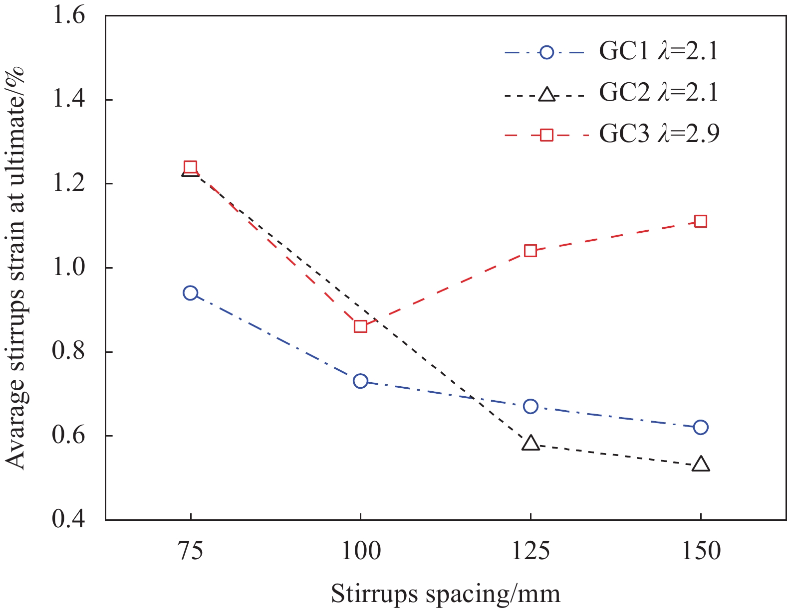
图 7 GC1-W100与GC1-P100中S2与S3位置的箍筋应变-跨中位移关系曲线Figure 7. Stirrups strain-midspan deflection curves at the location S2 and S3 of GC1-W100 and GC1-P100各组试件新型封闭缠绕式GFRP箍筋平均应变与箍筋间距关系如图8所示。可知,剪跨比为2.1时,箍筋平均应变随箍筋间距的增加基本呈整体降低的趋势,箍筋间距大于125 mm后,箍筋应变降低趋势变缓;这是由于在“拱机制”下剪力主要由混凝土斜压杆承担,当箍筋间距较小时,箍筋对混凝土压杆的约束作用较强所致。钢筋混凝土梁受剪试验研究[31-32]的相关结果表明,当剪跨比小于2.5时,箍筋能够提高混凝土承担的剪力,但自身承担的剪力较小;当剪跨比大于2.5时箍筋所承担的剪力会显著提高。本试验中剪跨比为2.9的试件在“梁机制”作用下箍筋承担的剪力更大,故其箍筋平均应变比剪跨比为2.1的试件更大。与小剪跨比试件不同的是,当箍筋间距从100 mm增加到150 mm时,箍筋平均应变反而呈增大的趋势,Ali等[33]的FRP筋混凝土梁受剪试验也发现了相似的规律。这是由于当箍筋间距较小时,穿过斜裂缝的箍筋数量增多,故箍筋应变平均值随之减小,同时由于试件GC3-W100发生了弯曲破坏,因此其箍筋应变也较小。
![]() 图 8 GFRP筋混凝土梁平均箍筋应变与箍筋间距关系Figure 8. Average stirrups strain-stirrups spacing relationship of concrete beams reinforced with GFRP reinforcement
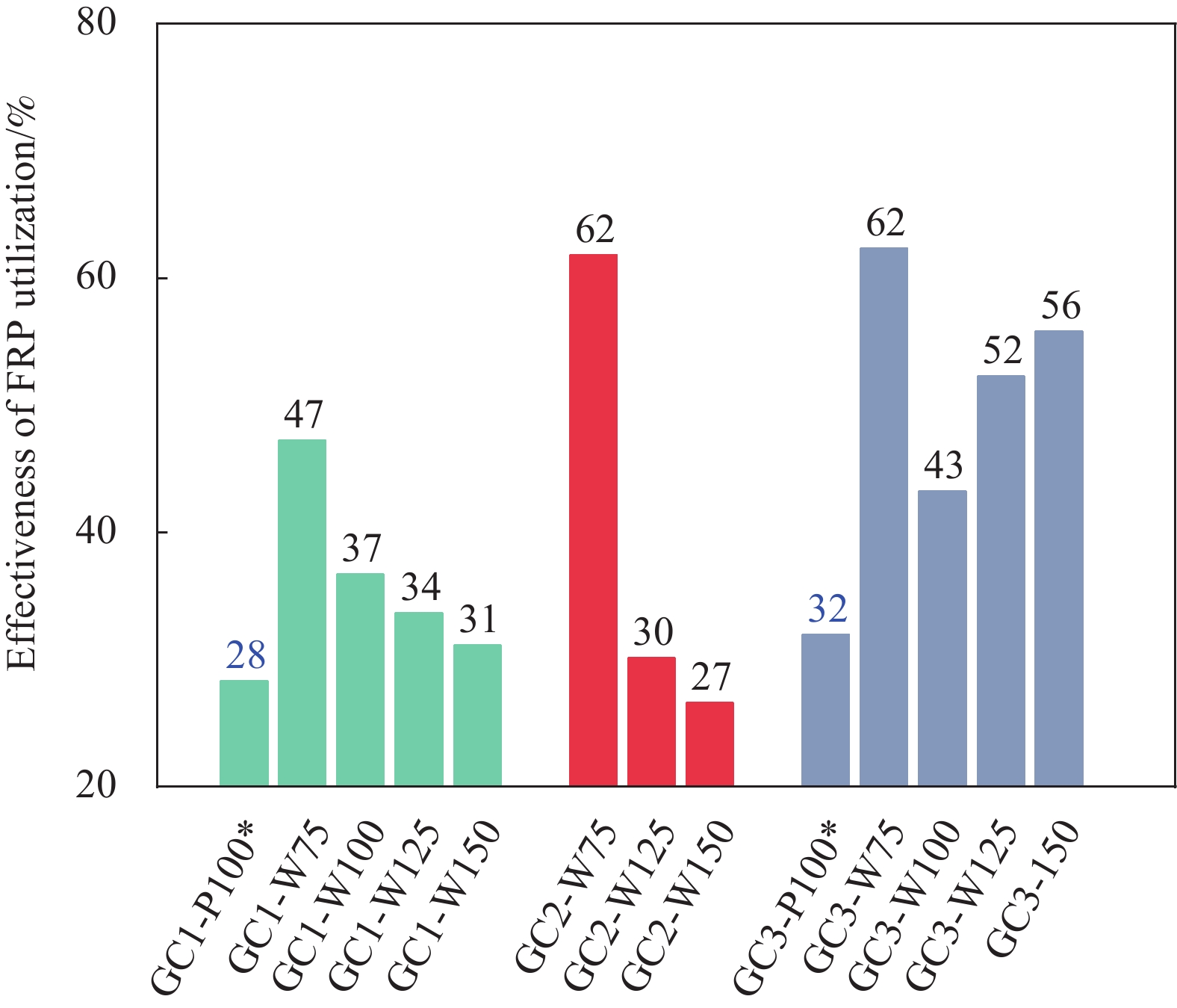
图 8 GFRP筋混凝土梁平均箍筋应变与箍筋间距关系Figure 8. Average stirrups strain-stirrups spacing relationship of concrete beams reinforced with GFRP reinforcement为比较箍筋对材料强度的利用程度,定义FRP箍筋的材料利用效率为承载力极限状态下箍筋平均应变与平直段极限受拉应变的比值。各个试件的箍筋材料利用效率如图9所示。可知,箍筋利用效率与平均应变的变化规律一致,整体随箍筋间距的增加而降低;剪跨比为2.1时,新型封闭缠绕式GFRP箍筋的材料利用效率为30%~62%(试件GC2-W150因缺陷导致稍小),剪跨比为2.9时利用率为43%~62%;箍筋间距相同时,新型封闭缠绕式GFRP箍筋的利用率达到拉挤成型箍筋的1.3倍以上,如试件GC1-W100和GC1-P100的箍筋利用率分别为37%和28%,GC3-W100和GC3-P100的箍筋利用率分别为43%和32%。
![]() 图 9 各GFRP筋混凝土梁试件箍筋的材料利用效率Figure 9. Effectiveness of FRP utilization of concrete beams reinforced with GFRP reinforcement*—Beams with pultruded stirrups
图 9 各GFRP筋混凝土梁试件箍筋的材料利用效率Figure 9. Effectiveness of FRP utilization of concrete beams reinforced with GFRP reinforcement*—Beams with pultruded stirrups2.4 GFRP筋混凝土梁受剪承载力预测
中国(GB 50608—2020)[19]、美国(ACI 440.1 R-15)[20]、加拿大(CSA S806-12)[21]、英国(BISE—1999)[22]与日本(JSCE—1997)[23]的FRP结构设计规范对FRP筋混凝土构件的受剪承载力V均考虑了混凝土和FRP箍筋两部分,均采用以下公式形式:
V=Vc+Vf (2) 其中:Vc为混凝土承担的剪力;Vf为FRP箍筋承担的剪力;Vc与Vf详细计算公式汇总于表4。
表 4 规范中的FRP筋混凝土梁受剪承载力计算公式Table 4. Code formula for calculating the shear capacity of FRP reinforced concrete beamsDesign code Concrete contribution Shear reinforcement contribution GB 50608—2020[19] Vc=0.86ftbc
c=kh0
k=√2ρfαE+(ρfαE)2−ρfαE
ρf=Af/bh0Vf=Afvffvh0s
ffv=minACI 440.1 R-15[20] {V_{\text{c} } } = \dfrac{2}{5}\sqrt { { {f}_{\rm{c}}'} } bk{h_{\text{0} } }
k = \sqrt {2{\rho _{\text{f}}}{\alpha _{\text{E}}} + {{\left( {{\rho _{\text{f}}}{\alpha _{\text{E}}}} \right)}^2}} - {\rho _{\text{f}}}{\alpha _{\text{E}}}{V_{\text{f} } } = \dfrac{ { {A_{ {\text{fv} } } }{f_{ {\text{fv} } } }{h_{\text{0} } } }}{s}
{f_{ {\text{fv} } } } = \min \left( {0.004{E_{ {\text{fv} } } },(0.05\dfrac{ { {r_{\text{b} } } }}{ { {d_{\text{b} } } }} + 0.3){f_{ {\text{fu} } } }} \right)CSA S806-12[21] {V_{\text{c}}} = 0.05{k_{\text{m}}}{k_{\text{r}}}{k_{\text{a}}}{k_{\text{s}}}{\left( {{{f}_{\rm{c}}'}} \right)^{\frac{1}{3}}}b{h_{\text{0}}}
0.11\sqrt {{{f}_{\rm{c}}'}} b{h_{\text{v}}} \leqslant {V_{\text{f}}} \leqslant 0.22\sqrt {{{f}_{\rm{c}}'}} b{h_{\text{v}}}
{k_{\text{m} } } = \sqrt {\dfrac{ { { {\text{V} } }{h_{\text{0} } } }}{ { {M } } } } \leqslant 1.0
{k_{\text{r}}} = 1 + {\left( {{E_{\text{f}}}{\rho _{\text{f}}}} \right)^{\frac{1}{3}}}
{k_{\text{a} } } = \dfrac{ {2.5{V }h_0} }{ { {M } }} \leqslant 2.5
{k_{\text{s} } } = \dfrac{ {750} }{ {450 + {h_{ {\text{0} } } } } } \leqslant 1.0{V } = \dfrac{ { {A_{ {\text{fv} } } }{f_{ {\text{fv} } } }{h_{\text{v} } }\cot \theta } }{s}
\theta = 30 + 7000{\varepsilon _x}
{\varepsilon _x} = \dfrac{ {M/{{h_0} } + V} }{ {2{E_{\text{f} } }{A_{\text{f} } } }}
{h_{\text{v}}} = \min \left( {0.9{h_0},0.72 h} \right)
{f_{{\text{fv}}}} = \min \left( {0.005{E_{{\text{fv}}}},0.4{f_{{\text{fu}}}},1\;200\;{\text{MPa}}} \right)BISE—1999[22] {V_{\text{c} } } = 0.79{\left( {100{\rho _{\text{f} } }\dfrac{ { {E_{\text{f} } } }}{ { {E_{\text{s} } } } } } \right)^{\frac{1}{3} } }{\left( {\dfrac{ {400} }{ { {h_0} } } } \right)^{\frac{1}{4} } }{\left( {\dfrac{ {1.25{f_{\text{c} }' } } }{ {25} } } \right)^{\frac{1}{3} } }b h_0 {V_{\text{f} } } = \dfrac{ {0.0025{A_{ {\text{fv} } } }{E_{ {\text{fv} } } }{h_0} } }{s} JSCE—1997[23] {V_{\text{c}}} = {\beta _{\text{d}}}{\beta _{\text{p}}}{{{f}}_{{\rm{vcd}}}}b{h_{\text{0}}}
{\beta _{\text{d} } } = {\left( {\dfrac{ {1000} }{ { {h_0} } } } \right)^{\frac{1}{4} } } \leqslant 1.5
{\beta _{\text{p} } }{\text{ = } }{\left( {1000 \times \dfrac{ { {\rho _{\text{f} } }{E_{\text{f} } } }}{ { {E_{\text{s} } } } } } \right)^{\frac{1}{3} } } \leqslant 1.5
f_{\mathrm{vcd} }=0.2 f_{c}^{\prime \frac{1}{3} } \leqslant 0.72 \mathrm{~N} / \mathrm{mm}^{2}{V_{\text{f} } } = \dfrac{ { {A_{ {\text{fv} } } }{E_{ {\text{fv} } } }{\varepsilon _{\text{f} } }_{\text{v} }z} }{s}
z{\text{ = }}{h_0}/1.15
{\varepsilon _{\text{f} } }_{\text{v} } = \sqrt { { {\left( {\dfrac{h}{ {0.3} } } \right)}^{ - \frac{1}{ {10} } } }{f_{\text{c} }' } \dfrac{ { {\rho _{\text{f} } }{E_{\text{f} } } }}{ { {\rho _{ {\text{fv} } } }{E_{ {\text{fv} } } } } } } \times {10^{ - 4} }Notes: ft—Tensile strength of concrete; b—Width of concrete beam; h—Depth of the beam; h0—Distance from compression fiber to the centroid of tension reinforcement; k—Ratio of depth of neutral axis to reinforcement depth; {\alpha _{\text{E}}}—Ratio of modulus of elasticity of FRP bars to modulus of elasticity of concrete; Af, Ef and {\rho _{\text{f}}} —The area, the modulus of elasticity and the reinforcement ratio of longitudinal bars; Afv, Efv, ffv and {\rho _{\text{f}}}_{\text{v}} —The area, the modulus of elasticity, the stress of FRP and the reinforcement ratio shear reinforcement; rb and db—Radius of the bend corner and the bar diameter of the pultruded stirrups; {f'_{\text{c}}} —Cylinder compressive strength of concrete; ka—Coefficient taking into account the effect of arch action; ks—Coefficient taking into account the effect of member size; km—Coefficient taking into account the effect of the moment at section; \theta —Angle between the diagonal shear crack and the horizontal axis; {\varepsilon _x} —Longitudinal strain at mid-depth of the section; Es—Modulus of elasticity of steel; s—Spacing of stirrups; M—Moment acting on the beam; V—Shear force acting on the beam; Vc—Shear force resisted by concrete; Vf—Shear force resisted by stirrups; ffu—Tensile strength of the straight portion of stirrups. 比较各国规范公式发现,五国规范中Vc的计算公式都考虑了纵筋配筋率的影响,加拿大规范还考虑了剪跨比小于2.5情况下“拱机制”的影响。中国、美国、英国与日本规范的Vf计算公式中暗含了混凝土斜裂缝倾角为45°的假设,而加拿大规范基于简化的修正斜压场理论计算了斜裂缝倾角[34],其计算过程需要迭代。各国规范都提出了箍筋应变限值,中美规范限制箍筋应变小于0.4%,加拿大规范限制箍筋应变小于0.5%,英国规范限制箍筋应变小于0.25%,日本规范则提出了箍筋应变的计算公式。此外,中国、美国与加拿大三国规范都限制FRP箍筋的应力小于其弯曲段强度。
采用各规范公式基于材料实测强度平均值对本文试件受剪承载力进行了计算,结果见表5。中美规范对FRP筋混凝土梁受剪承载力的计算结果基本相同,对新型封闭缠绕式GFRP箍筋混凝土梁受剪承载力的预测值平均仅为试验值的30%~45%,加拿大规范的预测值也仅为试验值的40%~60%,英国规范的预测值为试验值的约30%~50%,日本规范的预测值为试验值的约40%~65%。对于配置拉挤成型箍筋的试件,中美两国规范的预测值约为试验值的50%~75%,加拿大规范预测值约为试验值的60%~80%,英国规范预测值约为试验值的45%~65%,日本规范预测值约为试验值的45%~60%。表明五国规范均低估了FRP筋混凝土梁的受剪承载力,特别是对配置新型封闭缠绕式GFRP箍筋的混凝土梁;同时,剪跨比越小,规范预测值与试验值的差别越大,说明各国的规范未充分考虑“拱机制”对于受剪承载力的提高作用。
表 5 不同规范对FRP筋混凝土梁受剪承载力预测结果Table 5. Different code predictions of the shear capacity for FRP reinforced concrete beamsExperi-mental results GB 50608—2020 ACI 440.1 R-15 CSA S806-12 BISE—1999 JSCE—1997 Beam Vu/kN Vpre/kN Vpre/Vu Vpre, m/kN Vpre,m/Vu Vpre/kN Vpre/Vu Vpre,m/kN Vpre,m/Vu Vpre/kN Vpre/Vu Vpre,m/kN Vpre,m/Vu Vpre/kN Vpre/Vu Vpre,m/kN Vpre,m/Vu Vpre/kN Vpre/Vu Vpre,m Vpre,m/Vu GC1-P100 139.6 72.0 0.52 − − 72.0 0.52 − − 84.7 0.61 − − 62.9 0.45 − − 63.1 0.45 − − GC1-W75 151.4 57.1 0.38 162.6 1.07 57.1 0.38 162.5 1.07 68.0 0.45 114.4 0.76 53.7 0.35 170.6 1.13 60.5 0.40 176.5 1.17 GC1-W100 140.6 47.5 0.34 126.7 0.90 47.5 0.34 126.6 0.90 62.7 0.45 95.8 0.68 47.7 0.34 135.4 0.96 59.6 0.42 145.8 1.04 GC1-W125 131.6 41.8 0.32 105.1 0.80 41.8 0.32 105.0 0.80 59.2 0.45 84.6 0.64 44.1 0.33 114.2 0.87 59.0 0.45 127.5 0.97 GC1-W150 135.7 38.0 0.28 90.7 0.67 38.0 0.28 90.7 0.67 56.3 0.41 77.1 0.57 41.7 0.31 100.1 0.74 58.6 0.43 115.2 0.85 GC2-W75 168.4 60.3 0.36 165.8 0.98 60.3 0.36 165.7 0.98 80.4 0.48 118.9 0.71 57.4 0.34 174.3 1.03 61.7 0.37 176.5 1.05 GC2-W100 137.4 50.7 0.37 129.8 0.94 50.7 0.37 129.7 0.94 73.0 0.53 103.3 0.75 51.4 0.37 139.1 1.01 60.7 0.44 145.8 1.06 GC2-W125 139.9 44.9 0.32 108.3 0.77 44.9 0.32 108.2 0.77 68.2 0.49 95.7 0.68 47.8 0.34 117.9 0.84 60.0 0.43 127.5 0.91 GC2-W150 103.5 41.1 0.40 93.9 0.91 41.1 0.40 93.8 0.91 64.8 0.63 89.7 0.87 45.4 0.44 103.8 1.00 59.5 0.57 115.2 1.11 GC3-P100 101.8 75.2 0.74 − − 75.2 0.74 − − 80.3 0.79 − − 66.7 0.65 − − 61.6 0.61 − − GC3-W75 147.9 60.3 0.41 165.8 1.12 60.3 0.41 165.7 1.12 70.8 0.48 112.1 0.76 57.4 0.39 174.3 1.18 61.7 0.42 176.5 1.19 GC3-W100 117.5 50.7 0.43 129.8 1.10 50.7 0.43 129.7 1.10 64.4 0.55 93.4 0.79 51.4 0.44 139.1 1.18 60.7 0.52 145.8 1.24 GC3-W125 102.4 44.9 0.44 108.3 1.06 44.9 0.44 108.2 1.06 59.8 0.58 82.8 0.81 47.8 0.47 117.9 1.15 60.0 0.59 127.5 1.24 GC3-W150 92.9 41.1 0.44 93.9 1.01 41.1 0.44 93.8 1.01 56.6 0.61 78.5 0.84 45.4 0.49 103.8 1.12 59.5 0.64 115.2 1.24 Notes: Vu—Shear capacity; Vpre—Predicted shear capacity by design codes; Vpre, m—Predicted shear capacity using the average stirrups strain of the ruptured stirrup. 规范公式计算结果远低于试验结果,与规范对箍筋应变的限值较小有关。已有关于FRP筋梁的受剪试验表明,GFRP箍筋产生的应变远大于规范中的限值,而碳纤维增强树脂复合材料(CFRP)箍筋的应变与规范限值更接近[35-36]。由前文可知,本文试验中发生断裂的箍筋的应变达到了规范限值的3.3~4.0倍,这也是各国规范对新型封闭缠绕式GFRP箍筋混凝土梁受剪承载力预测结果误差较大的原因所在。试验中发生断裂的箍筋的最大应变平均值约为1.47%,若采用该值代替规范限值,则中美两国规范计算值约为试验值的95%,加拿大规范约为74%,英国规范计算值约为试验值的102%,日本规范计算值约为试验值的109%,计算结果与试验结果更接近,精度明显提高。因此,对于新型封闭缠绕式GFRP箍筋的断裂应变限值建议适当提高。
3. 结 论
(1) 新型封闭缠绕式玻璃纤维增强树脂复合材料(GFRP)箍筋的弯曲段强度与平直段受拉强度之比达到0.81,而拉挤成型箍筋仅为0.39,新型封闭缠绕式GFRP箍筋的弯曲段强度显著提高。
(2) 当剪跨比和箍筋间距相同时,新型封闭缠绕式GFRP箍筋混凝土梁表现出更高的开裂后刚度,其受剪承载力可以达到拉挤成型箍筋混凝土梁的1.16倍,新型封闭缠绕式GFRP箍筋的材料利用效率达到拉挤成型箍筋的1.3倍以上,而拉挤成型箍筋的搭接段发生了滑移。
(3) 剪跨比与箍筋间距对试件的平均箍筋应变有显著影响。剪跨比为2.9的试件的箍筋应变显著大于剪跨比为2.1的试件;当箍筋间距为75 mm时,试件的平均箍筋应变显著增大。
(4) 中国、美国、加拿大、英国和日本规范均显著低估了新型封闭缠绕式GFRP箍筋混凝土梁的受剪承载力,各规范的受剪承载力预测值与试验值之比约为30%~65%;规范中的应变限值显著低于试验测得的箍筋应变,建议适当提高新型封闭缠绕式GFRP箍筋的断裂应变限值。
-
![]()
图 1 试件截面与加载测量装置示意图
Figure 1. Schematic drawing of cross-sectional details, test set-up and instrumentation of beam test
![]()
图 2 纤维增强树脂复合材料(FRP)筋材的材料性能测试
Figure 2. Material test of fiber reinforced polymer (FRP) reinforcement
![]()
图 3 试件GC1-W75 (a)、GC2-W75 (b) 与GC3-W75 (c) 的裂缝开展过程
Figure 3. Crack propagation process of specimen GC1-W75 (a), GC2-W75 (b) and GC3-W75 (c)
![]()
图 4 GFRP筋混凝土梁的破坏模式
Figure 4. Failure mode of concrete beams reinforced with GFRP reinforcement
S1, S2, S3, S4—Stirrups with strain gauges attached
![]()
图 5 GFRP筋混凝土梁剪力-跨中位移曲线
Figure 5. Shear load-midspan deflection curves of concrete beams reinforced with GFRP reinforcement
![]()
图 7 GC1-W100与GC1-P100中S2与S3位置的箍筋应变-跨中位移关系曲线
Figure 7. Stirrups strain-midspan deflection curves at the location S2 and S3 of GC1-W100 and GC1-P100
![]()
图 8 GFRP筋混凝土梁平均箍筋应变与箍筋间距关系
Figure 8. Average stirrups strain-stirrups spacing relationship of concrete beams reinforced with GFRP reinforcement
![]()
图 9 各GFRP筋混凝土梁试件箍筋的材料利用效率
Figure 9. Effectiveness of FRP utilization of concrete beams reinforced with GFRP reinforcement
*—Beams with pultruded stirrups
表 1 试验工况
Table 1 Test matrix
Specimen Stirrups type s/mm ρ/% ρv/% λ GC1-P100 Pultruded 100 1.54 0.67 2.1 GC1-W75 New type 75 1.54 0.48 2.1 GC1-W100 New type 100 1.54 0.36 2.1 GC1-W125 New type 125 1.54 0.29 2.1 GC1-W150 New type 150 1.54 0.24 2.1 GC2-W75 New type 75 2.21 0.48 2.1 GC2-W100 New type 100 2.21 0.36 2.1 GC2-W125 New type 125 2.21 0.29 2.1 GC2-W150 New type 150 2.21 0.24 2.1 GC3-P100 Pultruded 100 2.21 0.67 2.9 GC3-W75 New type 75 2.21 0.48 2.9 GC3-W100 New type 100 2.21 0.36 2.9 GC3-W125 New type 125 2.21 0.29 2.9 GC3-W150 New type 150 2.21 0.24 2.9 Notes: ρ—Longitudinal reinforcement ratio; ρv—Shear reinforcement ratio; λ—Shear-span ratio; GC—Glass fiber-reinforced polymer (GFRP) stirrups reinforced concrete beams; P—Pultruded GFRP stirrups; W—Closed winding stirrups; s—Stirrups spacing.  下载: 导出CSV
表 2 FRP筋材力学性能参数
Table 2 Mechanical properties of FRP reinforcements
Material GFRP bar Pultruded stirrups New type stirrups d/mm or w×t/mm2 16 8 9×3 A/mm2 201 50 27 E/MPa 47.2 50.2 55.0 ffu/MPa 889 1059 1096 {\varepsilon _{{\text{fu}}}} /% 1.88 2.12 1.99 ffb/MPa − 415 892 ffb/ffu − 0.39 0.81 Notes: d—Diameter of pultruded GFRP bar or stirrups; w and t—Width and thickness of new type stirrups; A—Cross-sectional area of reinforcement; E—Elastic modulus; ffu—Tensile strength of the straight portion of reinforcements; {\varepsilon _{{\text{fu}}}} —Ultimate strain at the straight portion; ffb—Bend corner strength of stirrups.
下载: 导出CSV
表 3 GFRP筋混凝土梁受剪试验结果
Table 3 Shear test result of GFRP reinforced concrete beams
Beam Vu/kN Δp/mm Δu/mm Ks/(kN·mm−1) {\varepsilon _{{\text{max}}}} /% {\varepsilon _{{\text{avg}}}} /% {\varepsilon _{{\text{avg}}}}/{\varepsilon _{{\text{fu}}}} Stirrups ruptured
or notGC1-P100 139.6 10.28 11.75 26.8 1.01 0.60 0.28 No GC1-W75 151.4 13.02 13.02 33.8 1.36 0.94 0.47 Yes GC1-W100 140.6 10.25 10.25 30.3 0.95 0.73 0.37 No GC1-W125 131.6 9.51 9.51 28.8 0.89 0.67 0.34 No GC1-W150 135.7 10.82 10.82 30.8 1.11 0.62 0.31 No GC2-W75 168.4 15.93 15.93 46.4 1.54 1.23 0.62 Yes GC2-W100 137.4 8.42 10.31 45.8 − − − Yes GC2-W125 139.9 8.17 13.05 46.1 1.14 0.60 0.30 No GC2-W150 103.5 6.39 10.51 36.1 1.06 0.53 0.27 No GC3-P100 101.8 17.08 17.08 12.6 1.12 0.68 0.32 No GC3-W75 147.9 32.78 32.78 16.6 1.59 1.24 0.62 Yes GC3-W100 117.5 27.46 27.46 14.9 1.09 0.86 0.43 No GC3-W125 102.4 24.23 24.23 15.2 1.54 1.04 0.52 Yes GC3-W150 92.9 15.28 15.28 15.7 1.31 1.11 0.56 Yes Notes: Vu—Shear capacity; Δp—Midspan deflection at peak load; Δu—Midspan deflection at final failure (for the specimens failed at peak load, Δu is equal to the Δp); Ks—Stiffness after shear cracking, which was calculated as the slope of the line connecting the two points with loads of 40 kN and 90 kN respectively; {\varepsilon _{{\text{max}}}} —Maximal stirrups strain at ultimate; {\varepsilon _{{\text{avg}}}} —Average stirrups strain at ultimate; {\varepsilon _{\text{f}}}_{\text{u}} —Ultimate strain. The strain gauges of GC2-W100 were damaged prior to the failure.
下载: 导出CSV
表 4 规范中的FRP筋混凝土梁受剪承载力计算公式
Table 4 Code formula for calculating the shear capacity of FRP reinforced concrete beams
Design code Concrete contribution Shear reinforcement contribution GB 50608—2020[19] {V_{\text{c}}} = 0.86{f_{\text{t}}}bc
c = k{h_{\text{0}}}
k = \sqrt {2{\rho _{\text{f}}}{\alpha _{\text{E}}} + {{\left( {{\rho _{\text{f}}}{\alpha _{\text{E}}}} \right)}^2}} - {\rho _{\text{f}}}{\alpha _{\text{E}}}
{\rho _{\text{f}}} = {A_{\text{f}}}/b{h_{\text{0}}}{V_{\text{f} } } = \dfrac{ { {A_{ {\text{fv} } } }{f_{ {\text{fv} } } }{h_{\text{0} } } }}{s}
{f_{ {\text{fv} } } } = \min \left( {0.004{E_{ {\text{fv} } } },(0.05\dfrac{ { {r_{\text{b} } } }}{ { {d_{\text{b} } } }} + 0.3){f_{ {\text{fu} } } }} \right)ACI 440.1 R-15[20] {V_{\text{c} } } = \dfrac{2}{5}\sqrt { { {f}_{\rm{c}}'} } bk{h_{\text{0} } }
k = \sqrt {2{\rho _{\text{f}}}{\alpha _{\text{E}}} + {{\left( {{\rho _{\text{f}}}{\alpha _{\text{E}}}} \right)}^2}} - {\rho _{\text{f}}}{\alpha _{\text{E}}}{V_{\text{f} } } = \dfrac{ { {A_{ {\text{fv} } } }{f_{ {\text{fv} } } }{h_{\text{0} } } }}{s}
{f_{ {\text{fv} } } } = \min \left( {0.004{E_{ {\text{fv} } } },(0.05\dfrac{ { {r_{\text{b} } } }}{ { {d_{\text{b} } } }} + 0.3){f_{ {\text{fu} } } }} \right)CSA S806-12[21] {V_{\text{c}}} = 0.05{k_{\text{m}}}{k_{\text{r}}}{k_{\text{a}}}{k_{\text{s}}}{\left( {{{f}_{\rm{c}}'}} \right)^{\frac{1}{3}}}b{h_{\text{0}}}
0.11\sqrt {{{f}_{\rm{c}}'}} b{h_{\text{v}}} \leqslant {V_{\text{f}}} \leqslant 0.22\sqrt {{{f}_{\rm{c}}'}} b{h_{\text{v}}}
{k_{\text{m} } } = \sqrt {\dfrac{ { { {\text{V} } }{h_{\text{0} } } }}{ { {M } } } } \leqslant 1.0
{k_{\text{r}}} = 1 + {\left( {{E_{\text{f}}}{\rho _{\text{f}}}} \right)^{\frac{1}{3}}}
{k_{\text{a} } } = \dfrac{ {2.5{V }h_0} }{ { {M } }} \leqslant 2.5
{k_{\text{s} } } = \dfrac{ {750} }{ {450 + {h_{ {\text{0} } } } } } \leqslant 1.0{V } = \dfrac{ { {A_{ {\text{fv} } } }{f_{ {\text{fv} } } }{h_{\text{v} } }\cot \theta } }{s}
\theta = 30 + 7000{\varepsilon _x}
{\varepsilon _x} = \dfrac{ {M/{{h_0} } + V} }{ {2{E_{\text{f} } }{A_{\text{f} } } }}
{h_{\text{v}}} = \min \left( {0.9{h_0},0.72 h} \right)
{f_{{\text{fv}}}} = \min \left( {0.005{E_{{\text{fv}}}},0.4{f_{{\text{fu}}}},1\;200\;{\text{MPa}}} \right)BISE—1999[22] {V_{\text{c} } } = 0.79{\left( {100{\rho _{\text{f} } }\dfrac{ { {E_{\text{f} } } }}{ { {E_{\text{s} } } } } } \right)^{\frac{1}{3} } }{\left( {\dfrac{ {400} }{ { {h_0} } } } \right)^{\frac{1}{4} } }{\left( {\dfrac{ {1.25{f_{\text{c} }' } } }{ {25} } } \right)^{\frac{1}{3} } }b h_0 {V_{\text{f} } } = \dfrac{ {0.0025{A_{ {\text{fv} } } }{E_{ {\text{fv} } } }{h_0} } }{s} JSCE—1997[23] {V_{\text{c}}} = {\beta _{\text{d}}}{\beta _{\text{p}}}{{{f}}_{{\rm{vcd}}}}b{h_{\text{0}}}
{\beta _{\text{d} } } = {\left( {\dfrac{ {1000} }{ { {h_0} } } } \right)^{\frac{1}{4} } } \leqslant 1.5
{\beta _{\text{p} } }{\text{ = } }{\left( {1000 \times \dfrac{ { {\rho _{\text{f} } }{E_{\text{f} } } }}{ { {E_{\text{s} } } } } } \right)^{\frac{1}{3} } } \leqslant 1.5
f_{\mathrm{vcd} }=0.2 f_{c}^{\prime \frac{1}{3} } \leqslant 0.72 \mathrm{~N} / \mathrm{mm}^{2}{V_{\text{f} } } = \dfrac{ { {A_{ {\text{fv} } } }{E_{ {\text{fv} } } }{\varepsilon _{\text{f} } }_{\text{v} }z} }{s}
z{\text{ = }}{h_0}/1.15
{\varepsilon _{\text{f} } }_{\text{v} } = \sqrt { { {\left( {\dfrac{h}{ {0.3} } } \right)}^{ - \frac{1}{ {10} } } }{f_{\text{c} }' } \dfrac{ { {\rho _{\text{f} } }{E_{\text{f} } } }}{ { {\rho _{ {\text{fv} } } }{E_{ {\text{fv} } } } } } } \times {10^{ - 4} }Notes: ft—Tensile strength of concrete; b—Width of concrete beam; h—Depth of the beam; h0—Distance from compression fiber to the centroid of tension reinforcement; k—Ratio of depth of neutral axis to reinforcement depth; {\alpha _{\text{E}}}—Ratio of modulus of elasticity of FRP bars to modulus of elasticity of concrete; Af, Ef and {\rho _{\text{f}}} —The area, the modulus of elasticity and the reinforcement ratio of longitudinal bars; Afv, Efv, ffv and {\rho _{\text{f}}}_{\text{v}} —The area, the modulus of elasticity, the stress of FRP and the reinforcement ratio shear reinforcement; rb and db—Radius of the bend corner and the bar diameter of the pultruded stirrups; {f'_{\text{c}}} —Cylinder compressive strength of concrete; ka—Coefficient taking into account the effect of arch action; ks—Coefficient taking into account the effect of member size; km—Coefficient taking into account the effect of the moment at section; \theta —Angle between the diagonal shear crack and the horizontal axis; {\varepsilon _x} —Longitudinal strain at mid-depth of the section; Es—Modulus of elasticity of steel; s—Spacing of stirrups; M—Moment acting on the beam; V—Shear force acting on the beam; Vc—Shear force resisted by concrete; Vf—Shear force resisted by stirrups; ffu—Tensile strength of the straight portion of stirrups.
下载: 导出CSV
表 5 不同规范对FRP筋混凝土梁受剪承载力预测结果
Table 5 Different code predictions of the shear capacity for FRP reinforced concrete beams
Experi-mental results GB 50608—2020 ACI 440.1 R-15 CSA S806-12 BISE—1999 JSCE—1997 Beam Vu/kN Vpre/kN Vpre/Vu Vpre, m/kN Vpre,m/Vu Vpre/kN Vpre/Vu Vpre,m/kN Vpre,m/Vu Vpre/kN Vpre/Vu Vpre,m/kN Vpre,m/Vu Vpre/kN Vpre/Vu Vpre,m/kN Vpre,m/Vu Vpre/kN Vpre/Vu Vpre,m Vpre,m/Vu GC1-P100 139.6 72.0 0.52 − − 72.0 0.52 − − 84.7 0.61 − − 62.9 0.45 − − 63.1 0.45 − − GC1-W75 151.4 57.1 0.38 162.6 1.07 57.1 0.38 162.5 1.07 68.0 0.45 114.4 0.76 53.7 0.35 170.6 1.13 60.5 0.40 176.5 1.17 GC1-W100 140.6 47.5 0.34 126.7 0.90 47.5 0.34 126.6 0.90 62.7 0.45 95.8 0.68 47.7 0.34 135.4 0.96 59.6 0.42 145.8 1.04 GC1-W125 131.6 41.8 0.32 105.1 0.80 41.8 0.32 105.0 0.80 59.2 0.45 84.6 0.64 44.1 0.33 114.2 0.87 59.0 0.45 127.5 0.97 GC1-W150 135.7 38.0 0.28 90.7 0.67 38.0 0.28 90.7 0.67 56.3 0.41 77.1 0.57 41.7 0.31 100.1 0.74 58.6 0.43 115.2 0.85 GC2-W75 168.4 60.3 0.36 165.8 0.98 60.3 0.36 165.7 0.98 80.4 0.48 118.9 0.71 57.4 0.34 174.3 1.03 61.7 0.37 176.5 1.05 GC2-W100 137.4 50.7 0.37 129.8 0.94 50.7 0.37 129.7 0.94 73.0 0.53 103.3 0.75 51.4 0.37 139.1 1.01 60.7 0.44 145.8 1.06 GC2-W125 139.9 44.9 0.32 108.3 0.77 44.9 0.32 108.2 0.77 68.2 0.49 95.7 0.68 47.8 0.34 117.9 0.84 60.0 0.43 127.5 0.91 GC2-W150 103.5 41.1 0.40 93.9 0.91 41.1 0.40 93.8 0.91 64.8 0.63 89.7 0.87 45.4 0.44 103.8 1.00 59.5 0.57 115.2 1.11 GC3-P100 101.8 75.2 0.74 − − 75.2 0.74 − − 80.3 0.79 − − 66.7 0.65 − − 61.6 0.61 − − GC3-W75 147.9 60.3 0.41 165.8 1.12 60.3 0.41 165.7 1.12 70.8 0.48 112.1 0.76 57.4 0.39 174.3 1.18 61.7 0.42 176.5 1.19 GC3-W100 117.5 50.7 0.43 129.8 1.10 50.7 0.43 129.7 1.10 64.4 0.55 93.4 0.79 51.4 0.44 139.1 1.18 60.7 0.52 145.8 1.24 GC3-W125 102.4 44.9 0.44 108.3 1.06 44.9 0.44 108.2 1.06 59.8 0.58 82.8 0.81 47.8 0.47 117.9 1.15 60.0 0.59 127.5 1.24 GC3-W150 92.9 41.1 0.44 93.9 1.01 41.1 0.44 93.8 1.01 56.6 0.61 78.5 0.84 45.4 0.49 103.8 1.12 59.5 0.64 115.2 1.24 Notes: Vu—Shear capacity; Vpre—Predicted shear capacity by design codes; Vpre, m—Predicted shear capacity using the average stirrups strain of the ruptured stirrup.
下载: 导出CSV
-
[1] 张依睿, 魏洋, 柏佳文, 等. 纤维增强聚合物复合材料-钢复合圆管约束混凝土轴压性能预测模型[J]. 复合材料学报, 2019, 36(10):2478-2485. ZHANG Yirui, WEI Yang, BAI Jiawen, et al. Models for predicting axial compression behavior of fiber reinforced polymer-steel composite circular tube confined concrete[J]. Acta Materiae Compositae Sinica,2019,36(10):2478-2485(in Chinese).
[2] 缪坤廷, 魏洋, 朱超, 等. 钢管混凝土-FRP管海水海砂混凝土组合柱轴压模型[J]. 复合材料学报, 2022, 39(11): 5405-5416. MIAO Kunting, WEI Yang, ZHU Chao, et al. Model for stress-strain curves of concrete filled steel tube-seawater and sea sand concrete filled FRP tube composite columns under axial load[J]. Acta Materiae Compositae Sinica, 2022, 39(11):5405-5416(in Chinese).
[3] 柏佳文, 魏洋, 张依睿, 等. 新型碳纤维增强复合材料-钢复合管海水海砂混凝土圆柱轴压试验[J]. 复合材料学报, 2021, 38(9):3084-3093. BAI Jiawen, WEI Yang, ZHANG Yirui, et al. Axial compression behavior of new seawater and sea sand concrete filled circular carbon fiber reinforced polymer-steel composite tube columns[J]. Acta Materiae Compositae Sinica,2021,38(9):3084-3093(in Chinese).
[4] 叶列平, 冯鹏. FRP 在工程结构中的应用与发展[J]. 土木工程学报, 2006, 39(3):24-36. DOI: 10.3321/j.issn:1000-131X.2006.03.004 YE Lieping, FENG Peng. Applications and development of fiber-reinforced polymer in engineering structures[J]. China Civil Engineering Journal,2006,39(3):24-36(in Chinese). DOI: 10.3321/j.issn:1000-131X.2006.03.004
[5] BENMOKRANE B, MOHAMED H M. Use of fibre-reinforced polymer (FRP) rebars for building durable concrete infrastructure[C]//ALPHOSE Z. Insights and Innovations in Structural Engineering, Mechanics and Computation. Cape Town: CRC Press, 2016: 1518-1523.
[6] 尹世平, 华云涛, 徐世烺. FRP配筋混凝土结构研究进展及其应用[J]. 建筑结构学报, 2021, 42(1):134-150. YIN Shiping, HUA Yuntao, XU Shilang. A review on research progress and application of concrete structures internally reinforced with FRP bars[J]. Journal of Building Structures,2021,42(1):134-150(in Chinese).
[7] MARANAN G B, MANALO A C, BENMOKRANE B, et al. Shear behavior of geopolymer concrete beams reinforced with glass fiber-reinforced polymer bars[J]. ACI Structural Journal,2017,114(2):337-348.
[8] ALI M A, EL-SALAKAWY E. Seismic performance of GFRP-reinforced concrete rectangular columns[J]. Journal of Composites for Construction,2016,20(3):04015074. DOI: 10.1061/(ASCE)CC.1943-5614.0000637
[9] SHEHATA E, MORPHY R, RIZKALLA S. Fibre reinforced polymer shear reinforcement for concrete members: Behaviour and design guidelines[J]. Canadian Journal of Civil Engineering, 2000, 27(5): 859-872.
[10] EL-SAYED A K, EL-SALAKAWY E, BENMOKRANE B. Mechanical and structural characterization of new carbon FRP stirrups for concrete members[J]. Journal of Compo-sites for Construction,2007,11(4):352-362. DOI: 10.1061/(ASCE)1090-0268(2007)11:4(352)
[11] AHMED E, EL-SAYED A, EL-SALAKAWY E, et al. Bend strength of FRP stirrups: Comparison and evaluation of testing methods[J]. Journal of Composites for Construction,2009,14(1):3-10.
[12] PENG F, XUE W C. Evaluation of bend strength calculation of fiber-reinforced polymer stirrups[C]//WU Z S. Joint Conference of the 12th International Symposium on Fiber Reinforced Polymers for Reinforced Concrete Structures (FRPRCS-12) & the 5th Asia Pacific Conference on Fiber Reinforced Polymers in Structures (APFIS-2015). Nanjing: Southeast University, 2015: 21.
[13] IMJAI T, GUADAGNINI M, PILAKOUTAS K. Curved FRP as concrete reinforcement[J]. Proceedings of the Institution of Civil Engineers-Engineering and Computational Mechanics,2009,162(3):171-178. DOI: 10.1680/eacm.2009.162.3.171
[14] JUMAA G B, YOUSIF A R. Size effect on the shear failure of high-strength concrete beams reinforced with basalt FRP bars and stirrups[J]. Construction and Building Materials,2019,209(10):77-94.
[15] 康明睿, 薛伟辰. 配FRP箍筋混凝土梁的抗剪性能研究进展[J]. 华北水利水电学院学报, 2015, 36(2): 15-20. KANG Mingrui, XUE Weichen. A review on research progress of shear behavior of concrete beams reinforced with FRP stirrups[J]. Journal of North China University of Water Resources and Electric Power, 2015, 36(2): 15-20(in Chinese).
[16] 侯慕轶. 碳纤维筋混凝土梁受剪性能试验研究[D]. 绵阳: 西南科技大学, 2017. HOU Muyi. Experiment studies on the shear performance of concrete beam with CFRP bars[D]. Mianyang: Southwest University of Science and Technology, 2017(in Chinese).
[17] 彭俊桢. 玄武岩纤维(BFRP)筋混凝土梁的受剪性能研究[D]. 厦门: 厦门大学, 2019. PENG Junzhen. Research on shear performance of BFRP reinforced concrete beams[D]. Xiamen: Xiamen University, 2019(in Chinese).
[18] WHITEHEAD P A, IBELL T J. Novel shear reinforcement for fiber-reinforced polymer-reinforced and prestressed concrete[J]. ACI Structural Journal,2005,102(2):286-294.
[19] 中华人民共和国住房和城乡建设部. 纤维增强复合材料建设工程应用技术规范: GB 50608—2020[S]. 北京: 中国标准出版社, 2010. Ministry of Housing and Urban-Rural Development of People’s Republic of China. Technical standard for fiber reinforced polymer (FRP) in construction: GB 50608—2020[S]. Beijing: China Standards Press, 2020(in Chinese).
[20] American Concrete Institute. Guide for the design and construction of structural concrete reinforced with fiber reinforced polymer (FRP) bars: ACI 440.1 R-15[S]. Farmington Hills: American Concrete Institute, 2015.
[21] Canadian Standard Association. Design and construction of building components with fibre reinforced polymers: CSA S806-12[S]. Toronto: Canadian Standards Association International, 2012.
[22] British Institution of Structural Engineers. Interim guidance on the design of reinforced concrete structures using fiber composite reinforcement: BISE—1999[S]. London: British Institution of Structural Engineers, 1999.
[23] Japan Society of Civil Engineers. Recommendation for design and construction of concrete structures using continuous fiber reinforcing materials: JSCE—1997[S]. Tokyo: Japan Society of Civil Engineers, 1997.
[24] DONG H, WANG D, WANG Z, et al. Axial compressive behavior of square concrete columns reinforced with innovative closed-type winding GFRP stirrups[J]. Compo-site Structures,2018,192:115-125. DOI: 10.1016/j.compstruct.2018.02.092
[25] 董恒磊. 配置GFRP纵筋与新型箍筋的混凝土墩柱约束机理与抗震性能[D]. 哈尔滨: 哈尔滨工业大学, 2020. DONG Henglei. Confinement mechanism and seismic performance of concrete piers reinforced with GFRP rebars and innovativeties[D]. Harbin: Harbin Institute of Technology, 2020(in Chinese).
[26] 中国国家标准化管理委员会. 纤维增强复合材料筋基本力学性能试验方法: GB/T 30022—2013[S]. 北京: 中国标准出版社, 2013. Standardization Administration of China. Test method for basic mechanical properties of fiber reinforced polymer bar: GB/T 30022—2013[S]. Beijing: Standards Press of China, 2013(in Chinese).
[27] American Society of Testing Materials. Standard test method for tensile properties of polymer matrix composite materials: ASTM D3039/3039 M-00[S]. West Conshohocken: American Society of Testing Materials International, 2000.
[28] American Concrete Institute. Guide test methods for fiber reinforced polymer (FRP) composites for reinforcing or strengthening concrete and masonry structures: ACI 440.3 R-12[S]. Farmington Hills: American Concrete Institute, 2012.
[29] MIHAYLOV B I, BENTZ E C, COLLINS M P. Behavior of large deep beams subjected to monotonic and reversed cyclic shear[J]. ACI Structural Journal, 2010, 107(6): 726-734.
[30] JEONG J P, KIM W. Shear resistant mechanism into base components: Beam action and arch action in shear-critical RC members[J]. International Journal of Concrete Structures and Materials,2014,8(1):1-14. DOI: 10.1007/s40069-013-0064-x
[31] HU B, WU Y F. Effect of shear span-to-depth ratio on shear strength components of RC beams[J]. Engineering Structures,2018,168:770-783. DOI: 10.1016/j.engstruct.2018.05.017
[32] 易伟建, 谭童. 钢筋混凝土有腹筋梁受剪机理试验研究[J]. 建筑结构学报, 2022, 43(9): 210-221. YI Weijian, TAN Tong. Experimental study on shear mechanism of reinforced concrete beams with stirrups[J]. Journal of Building Structures, 2022, 43(9): 210-221(in Chinese)
[33] ALI A H, MOHAMED H M, BENMOKRANE B. Shear behavior of circular concrete members reinforced with GFRP bars and spirals at shear span-to-depth ratios between 1.5 and 3.0[J]. Journal of Composites for Construction,2016,20(6):04016055. DOI: 10.1061/(ASCE)CC.1943-5614.0000707
[34] RAZAQPUR A G, SPADEA S. Shear strength of FRP reinforced concrete members with stirrups[J]. Journal of Composites for Construction,2015,19(1):04014025. DOI: 10.1061/(ASCE)CC.1943-5614.0000483
[35] JOHNSON D T, SHEIKH S A. Experimental investigation of glass fiber-reinforced polymer-reinforced normal-strength concrete beams[J]. ACI Structural Journal,2016,113(6):1165-1174.
[36] SPADEA S, ORR J, NANNI A, et al. Wound FRP shear reinforcement for concrete structures[J]. Journal of Compo-sites for Construction,2017,21(5):04017026. DOI: 10.1061/(ASCE)CC.1943-5614.0000807
-
期刊类型引用(4)
1. 卢利,周振,周浩然,陈苇,麦广浩. 箍筋类型对GFRP筋增强混凝土梁性能的影响. 广东土木与建筑. 2024(03): 61-65 .  百度学术
百度学术
2. Lili Xing,Shengjiang Sun,Kuihua Mei,Yiping Guo,Zhenhong Yang. Research progress on short-term mechanical properties of FRP bars and FRP-reinforced concrete beams. Journal of Traffic and Transportation Engineering(English Edition). 2024(02): 245-270 . 必应学术
3. 江佳斐,吕佳豪,薛伟辰. FRP箍筋强度保留率分布模型与可靠性分析. 建筑材料学报. 2024(06): 496-502 . 百度学术
4. 王锦辉,陆春华,冯晨阳,朱学武. 配FRP矩形箍混凝土梁的受剪承载力研究现状. 硅酸盐通报. 2024(08): 2726-2736 . 百度学术
其他类型引用(5)
-


计量
- 文章访问数: 1540
- HTML全文浏览量: 776
- PDF下载量: 116
- 被引次数: 9
