

Advances on thermal insulation applications of aerogels
-
摘要:
气凝胶独特的三维纳米网络结构使其同时具有超低密度和超低热导率的特性,是理想的轻量化隔热保温材料,在微电子、航空航天等对重量要求严格的领域行业具有很大吸引力,激起科研人员广泛的研究兴趣,并对该领域进行了大量的科研工作。本综述首先分析了气凝胶材料的制备方式,重点论述了溶胶-凝胶法、分子路线法、静电纺丝法、3D打印等方法并对气凝胶材料在隔热领域的应用进行了总结;后续又对气凝胶的材料选用等方面进行探讨,最后展望和分析气凝胶的未来研究重点方向。
Abstract:The unique three-dimensional network of aerogel endowed it with characteristics of ultra-low density and ultra-low thermal conductivity, These characteristics made it to an ideal lightweight thermal insulation material. And has highly attractive in fields of microelectronics, aerospace and other fields with strict weight requirements. Therefore, it sparks extensive research interest of researchers work in this field. This review first analyzes the preparation methods of aerogel materials, mianly focus on sol-gel method, molecular route method, electrospinning method, 3D printing and other methods in the thermal insulation application of aerogel. Subsequently, discussions on material selection of aerogel are carried out. Finally, a brief summary of prospect and analysis on the future research directions of aerogels are made.
-
Keywords:
- aerogel /
- thermal insulation /
- sol-gel /
- drying method /
- aerogel material
-
随着全球能源结构的转型和对清洁能源需求的不断增长,氢能作为一种清洁、高效的能源载体,正逐渐成为新能源领域的研究热点[1-3]。然而,氢能的高效储存和运输是实现其广泛应用的关键技术挑战之一。在众多储氢技术中,纤维缠绕复合材料高压储氢技术因技术成熟度和成本优势,被广泛应用于航空航天和交通运输领域[4-7]。复合材料缠绕层作为载荷承担的主体,是决定气瓶结构承载能力和安全性的重要因素。爆破压力是高压储氢容器设计的关键指标之一。为提高复合压力容器的结构效率,降低储氢成本,通常在设计阶段使用有限元方法对缠绕结构的爆破行为进行分析并对缠绕层进行优化。目前储氢气瓶的有限元分析中,直接将气瓶缠绕层看作不同角度纤维层的堆叠,基于层合结构数值模型对纤维缠绕储氢气瓶的结构性能进行评估[8-10]。但纤维束在螺旋缠绕过程中会产生交叉起伏,直接采用层合数值模型难以考虑交叉起伏形态特征对缠绕层力学性能的影响[11-15],影响爆破压力预测结果的准确性。
已有研究发现纤维束的交叉起伏会降低复合材料的力学性能[16-18]。Shen等[19]建立了一种介观模型来研究纤维交叉起伏对缠绕复合材料刚度的影响,证明了纤维交叉起伏会产生显著影响纤维缠绕复合材料(Filament-wound composites,FWC)的弹性参数。Shen提出,缠绕纤维束厚度也是影响力学性能的一个关键因素。Henry等[20]研究了纤维缠绕圆筒在压缩载荷下损伤行为,发现纤维起伏会降低纤维缠绕圆筒的压缩强度。Chang等[21]研究了缠绕圆筒在拉伸、扭转和多轴载荷下的损伤响应,结果表明纤维损伤首先出现在缠绕交叉起伏区域,并沿此区域扩展。Chang等[22]进一步建立缠绕圆筒全尺寸模型,基于缠绕特征区域赋予材料属性,结果证明这种模型可以模拟缠绕圆筒的损伤过程。Hameed等[23]提出了一种模拟缠绕图案特征的压力容器分区建模方法。与传统的有限元模型相比,该模型可以捕捉缠绕图案对应变分布的影响。Arellano等[24]则采用数字图像相关技术(DIC)对缠绕平板应变分布进行了监测,验证了分区建模方法的合理性。在此基础上,肖磊等[25]使用数值仿真和实验手段相结合的方法进一步对比了FWC平板和标准层合复合材料(Standard laminate composites,SLC)平板的应变分布,结果证明缠绕结构菱形特征图案中部纤维交叉起伏区域存在明显的应变集中现象,是导致该区域损伤起始的主要原因。
在复合材料气瓶结构设计中,有限元分析是常用的手段之一[26]。当前报道的建模类型包括轴对称模型[11]和三维模型[15]两大类。根据Lekhnitskii假设[27],材料围绕一个轴是对称的,使用轴对称模型不会影响爆破压力结果,并且可以有效提高计算效率[28]。相比轴对称模型,三维模型可以考虑纤维缠绕变角度等特征,开展基于三维尺度的水压爆破和低速冲击分析[29-30],可提供更高的分析精度。三维壳单元模型通过在壳结构上定义复合材料厚度和方向模拟气瓶结构[31-35],从而降低气瓶建模的难度。壳单元在建模难度和计算效率上具有优势[36-38],但三维实体单元[39-42]更能反映缠绕层的几何特征,更适合于精确计算和捕捉复合材料层间的损伤行为。为了研究结构失效机制,许多损伤失效模型被应用在气瓶有限元分析中,包括Hashin失效准则[43]、Puck失效准则[31]、Hashin–Rottem失效准则[35]等。为了提高三维实体模型的计算效率,减少结构模型的尺寸,借助周期性边界条件,建立气瓶的1/4[44]、1/12[8]和1/72[39]模型,是当前常用的有效手段。
在已有的文献报道中,气瓶多基于简化的轴对称模型和三维模型,将缠绕层假设为层合结构进行分析,忽略了纤维缠绕结构中的纤维交叉起伏对纤维方向强度的影响。但对缠绕结构的研究已经表明,纤维交叉起伏会影响缠绕结构的力学性能。因此在复合材料气瓶结构分析中,忽略纤维交叉起伏影响会减低预测精度,难以准确分析缠绕结构的失效模式和强度。虽然通过建立包含纤维束形态的气瓶介观模型,可以直接考虑纤维束交叉起伏特征,但与平板模型和圆筒模型相比,气瓶模型更为复杂,在复合材料气瓶结构分析中使用该方法会显著增加建模难度,并降低计算效率。
为了评估纤维束介观交叉起伏形态的影响,实现气瓶爆破行为的准确预测,并兼顾计算效率,本文提出一种考虑纤维强度折减效应对气瓶层合模型进行修正的爆破失效分析方法(折减分析方法),并与不考虑纤维强度折减效应的爆破失效分析方法(传统分析方法)进行了对比。首先,采用实验和数值模拟相结合的方法研究纤维交叉起伏特征对缠绕平板拉伸行为的影响机制,探索缠绕参数对纤维拉伸强度的影响规律。然后,通过对传统层合模型分析方法中各角度缠绕层纤维方向拉伸强度进行修正,发展了一种考虑纤维交叉起伏影响的Ⅳ型气瓶爆破行为预测数值分析方法。最后,分别使用折减分析方法和传统分析方法,开展3种不同铺层Ⅳ型气瓶的爆破失效分析,并与对应铺层的气瓶水压爆破试验结果进行对比,验证本文提出的Ⅳ型气瓶爆破失效分析方法的准确性。
1. 纤维强度折减效应研究
在纤维螺旋缠绕过程中,会形成一个以纤维交叉起伏为特征的区域,如图1所示。由纤维交叉引起的纤维束起伏可能会影响复合材料的拉伸强度。纤维强度折减效应研究选择了一个含纤维交叉起伏的特征区域作为研究对象,制备了纤维缠绕的FWC平板试样,用来模拟典型的纤维束交叉起伏特征。同时制备了相同角度的标准层合结构的SLC平板试样作为对照组。沿纤维的+α°方向,对两类试样进行了单向拉伸的实验和仿真的对比分析,获得纤维交叉起伏结构的强度折减规律。
1.1 实 验
首先进行FWC平板和SLC平板试样制备。如图2所示,将预浸料裁成长400 mm、宽6 mm的预浸带,模拟缠绕过程交叉铺贴获得缠绕平板,铺贴过程不考虑张力作用,采用真空袋压法制备了4组缠绕角度为±10°、±20°、±30°和±40°的FWC平板试样。作为对比,制备了4组相同角度的SLC平板试样。试样整体厚度为0.43 mm,共两层,其中试样长度方向沿着+α°纤维束方向,实际平板试样的纤维束夹角为2α°。
![]() 图 2 固化成型和拉伸试样FWC—Filament-wound compositesFigure 2. Curing process and tensile specimens
图 2 固化成型和拉伸试样FWC—Filament-wound compositesFigure 2. Curing process and tensile specimens在电子万能试验机(LD23.104,力试科学仪器有限公司)上对试样进行拉伸试验,参考标准ASTM D3039[45]进行加载,并使用DIC设备(Vic-2D,Correlated Solutions Europe)监测加载过程中试样表面的位移场和应变场,如图3所示。为确保DIC方法监测应变场的准确性,在试验前先对试样表面进行散斑喷涂。然后进行试样和设备安装,在加载过程中设置拍摄频率为1 Hz,拉伸位移速度为2 mm/min。拉伸载荷通过试验机传感器获得,实际位移通过DIC的非接触式引伸计获得。
![]() 图 3 实验装置和加载方式DIC—Digital image correlation technologyFigure 3. Experimental equipment and loading apparatus
图 3 实验装置和加载方式DIC—Digital image correlation technologyFigure 3. Experimental equipment and loading apparatus1.2 有限元分析
基于ABAQUS/Explicit求解器建立了三维有限元模型,采用Hashin失效起始准则和渐进损伤演化方式模拟FWC平板和SLC平板试样的拉伸失效行为。为了在模型中准确建立纤维交叉起伏的细节特征,使用光学显微镜拍摄并测量了不同缠绕角度下FWC平板试样截面参数,如图4(a)所示。将测量的起伏角度作为评估缠绕结构起伏特征的关键参数。同时为了建立双层厚度的纤维缠绕结构平板模型,进行缠绕层厚度对纤维折减系数影响的研究,进一步制备了双层厚度的缠绕结构试样,并测量了这些试样交叉区域的起伏角度,如图4(b)所示。图4(c)、图4(d)为单层和双层FWC试样的纤维起伏角度随缠绕角度的变化规律,单层厚度试样平均起伏角度分别为7.6°、7.7°、8.1°和8.6°,双层厚度试样的平均起伏角度分别为9.7°、10.6°、11.2°和12.5°。
在Abaqus有限元软件中建立了FWC平板和SLC平板的有限元模型。SLC平板的有限元模型和边界条件设置如图5所示,在左侧加载区域的上下表面施加固定约束,在右侧加载区域施加位移加载,加载速率与试验一致。样品的拉伸区域长度为100 mm,为了避免边界处的应力集中导致样品过早失效,在拉伸区域的左侧和右侧各7 mm长度区域内未设置材料失效,而在拉伸区域中间的86 mm长度区域内考虑了材料失效。
![]() 图 4 起伏角度(α)随缠绕角度变化:(a)单层纤维的起伏形态;(b) 2层纤维的起伏形态;(c)单层纤维变化规律;(d) 2层纤维变化规律Figure 4. Variations of undulation angle (α) with the winding angle: (a) Undulation feature of single layer; (b) Undulation feature of 2 layers; (c) Variation curve of single layer; (d) Variation curve of 2 layers
图 4 起伏角度(α)随缠绕角度变化:(a)单层纤维的起伏形态;(b) 2层纤维的起伏形态;(c)单层纤维变化规律;(d) 2层纤维变化规律Figure 4. Variations of undulation angle (α) with the winding angle: (a) Undulation feature of single layer; (b) Undulation feature of 2 layers; (c) Variation curve of single layer; (d) Variation curve of 2 layers![]() 图 5 标准层合复合材料(SLC)平板模型和加载条件Figure 5. Model of standard laminate composites (SLC) plate and its loading conditions
图 5 标准层合复合材料(SLC)平板模型和加载条件Figure 5. Model of standard laminate composites (SLC) plate and its loading conditions根据显微镜观察到的FWC平板试样截面交叉起伏几何特征,建立了FWC平板试样的细节模型,如图6所示。模型中的纤维起伏角度与测量的纤维起伏平均角度相同,在交叉起伏边缘和纤维束之间的间隙存在,并使用树脂对这些间隙进行了填充。图7为建立的FWC平板的有限元模型,边界条件和加载方式与试验保持一致。在FWC平板左侧宽50 mm区域上下表面施加固定约束,在FWC平板右侧宽50 mm区域上下表面设置向右的拉伸位移载荷,加载速率与试验一致。为避免边界应力集中导致样品过早失效,试样中间宽86 mm区域的复合材料设置了材料失效,两侧7 mm区域未设置材料失效。
![]() 图 6 FWC平板中纤维交叉起伏形态:(a)实验观测截面图;(b)建模示意图Figure 6. Undulation of fiber bundle in FWC plate: (a) Experimental image; (b) Modeling image
图 6 FWC平板中纤维交叉起伏形态:(a)实验观测截面图;(b)建模示意图Figure 6. Undulation of fiber bundle in FWC plate: (a) Experimental image; (b) Modeling image单向纤维束材料参数的弹性模量、泊松比和极限强度等参数通过试验测试获得,试验测试参考ASTM测试标准[45-49],详见表1。
![]() 图 7 不同缠绕角度FWC平板有限元模型:(a) ±10°;(b) ±20°;(c) ±30°;(d) ±40°Figure 7. Finite element (FE) models of FWC plates with different winding angles: (a) ±10°; (b) ±20°; (c) ±30°; (d) ±40°表 1 单向纤维束材料参数Table 1. Material properties of unidirectional fiber bundle
图 7 不同缠绕角度FWC平板有限元模型:(a) ±10°;(b) ±20°;(c) ±30°;(d) ±40°Figure 7. Finite element (FE) models of FWC plates with different winding angles: (a) ±10°; (b) ±20°; (c) ±30°; (d) ±40°表 1 单向纤维束材料参数Table 1. Material properties of unidirectional fiber bundleItems Value Longitudinal modulus, E11/GPa 125.4 Transverse modulus, E22 =E33/GPa 7.7 In-plane shear modulus, G12=G13/GPa 3.8 Out-of-plane shear modulus, G23/GPa 4.8 Major Poisson's ratio, μ12 = μ13 0.33 Through-thickness Poisson's ratio, υ23 0.35 Longitudinal tensile strength, XT/GPa 2.18 Longitudinal compressive strength, XC/GPa 1.2 Transverse tensile strength, YT/MPa 60 Transverse compressive strength, YC/MPa 140 Density of laminate, ρ/(kg·m−3) 1600 Tensile fracture energy of fiber, Gft/(N·mm−1) 133 Compressive fracture energy of fiber, Gfc/(N·mm−1) 40 Tensile fracture energy of matrix, Gmt/(N·mm−1) 0.6 Compressive fracture energy of matrix,Gmc/(N·mm−1) 2.1 Elastic modulus of resin, E/GPa 3.0 Density of resin, ρr/(kg·m−3) 1200 Poisson's ratio of resin, μ 0.3 采用Hashin失效准则对纤维和基体的起始损伤进行判定,采用基于能量的线性本构描述材料损伤起始后的演化行为。平板拉伸失效分析和气瓶的爆破分析采用相同的失效准则,如下式:
纤维拉伸失效(σ11 > 0):
(σ11XT)2⩾1 (1) 纤维压缩失效(σ11 < 0):
(σ11XC)2⩾1 (2) 基体拉伸失效(σ22 > 0):
(σ22XT)2+(σ12S12)2+((σ23)2+σ22σ23S23)2⩾1 (3) 基体压缩失效(σ22 < 0):
(σ22S22)2+(σ22+σ33YC)((YC2S23)2−1)+ (σ223−σ22σ23)S223+(σ12S12)2+(σ13S13)2⩾1 (4) 面内损伤演化:
di=max{0,min{1,εfeqεeq−ε0eqεeq(εfeq−ε0eq)}} (5) 其中:XT、XC分别为纤维方向拉伸和压缩强度;YC为垂直于纤维方向压缩强度;S22为垂直于纤维方向拉伸强度;S12、S13、S23为剪切强度;σ11、σ22分别为纤维方向和垂直于纤维方向的正应力;σ12、σ13和σ23为剪切应力;ε0eq为复合材料结构失效起始状态下的等效应变;εfeq为复合材料结构完全失效状态下的等效应变;εeq为复合材料结构当前状态下的等效应变[50]。
1.3 结果对比与分析
图8为0.43 mm厚度4组不同缠绕角的FWC平板和SLC平板拉伸实验的位移-载荷曲线。在加载过程中加强片和试件之间会发生滑动,为了使位移值更接近实际值,位移值使用DIC系统的电子引伸计功能测量,载荷值采用试验机记录的加载力。从图中发现,FWC平板的极限强度低于相同角度的SLC平板试件,FWC平板的承载能力显著降低。与相同角度的SLC平板对比,FWC平板刚度分别降低了3.70%、2.93%、1.50%和0.55%,均小于5.00%。FWC平板刚度降低并不明显,因此本文重点讨论纤维强度折减效应。
图9和图10分别为实验和有限元分析中得到的FWC平板和SLC平板的长度方向应变场(εyy)。两者结果相比,FWC平板的实验和模拟应变场都表现出应变集中。相反,SLC平板的应变场没有显示出应变集中,尽管位移增加,SLC平板的表面应变保持着相对均匀的分布。有限元与实验的表面应变结果具有良好的一致性。
![]() 图 8 FWC平板和SLC平板的位移-载荷试验曲线:(a) ±10°;(b) ±20°;(c) ±30°;(d) ±40°Figure 8. Experimental displacement-load curves of FWC and SLC plate specimens: (a) ±10°; (b) ±20°; (c) ±30°; (d) ±40°
图 8 FWC平板和SLC平板的位移-载荷试验曲线:(a) ±10°;(b) ±20°;(c) ±30°;(d) ±40°Figure 8. Experimental displacement-load curves of FWC and SLC plate specimens: (a) ±10°; (b) ±20°; (c) ±30°; (d) ±40°![]() 图 9 数字图像相关技术(DIC)监测FWC平板和SLC平板长度方向应变(εyy)结果:(a) ±10°;(b) ±20°;(c) ±30°;(d) ±40°Figure 9. Distribution of vertical strain (εyy) of FWC and SLC plates monitored by DIC: (a) ±10°; (b) ±20°; (c) ±30°; (d) ±40°
图 9 数字图像相关技术(DIC)监测FWC平板和SLC平板长度方向应变(εyy)结果:(a) ±10°;(b) ±20°;(c) ±30°;(d) ±40°Figure 9. Distribution of vertical strain (εyy) of FWC and SLC plates monitored by DIC: (a) ±10°; (b) ±20°; (c) ±30°; (d) ±40°![]() 图 10 FWC平板和SLC平板长度方向仿真应变结果:(a) ±10°;(b) ±20°;(c) ±30°;(d) ±40°Figure 10. Numerical predicted distribution of vertical strain fields of FWC and SLC plates: (a) ±10°; (b) ±20°; (c) ±30°; (d) ±40°
图 10 FWC平板和SLC平板长度方向仿真应变结果:(a) ±10°;(b) ±20°;(c) ±30°;(d) ±40°Figure 10. Numerical predicted distribution of vertical strain fields of FWC and SLC plates: (a) ±10°; (b) ±20°; (c) ±30°; (d) ±40°图11为两种平板各角度仿真(FEA)和实验(EXP)的位移-载荷曲线及FWC平板的纤维拉伸失效云图。结果表明,仿真与实验所得的平板拉伸刚度高度一致,且在拉伸极限强度方面的误差较小,这验证了数值分析与实验结果之间具有很好的一致性。右侧云图为FWC平板纤维拉伸失效过程仿真结果。图11中载荷达到 a点时,FWC平板少数单元应力水平达到纤维拉伸起始失效判据,单元开始失效,单元刚度出现退化;随着继续载荷达到b点,失效面积逐渐扩展;最终加载至c点,缠绕交叉区域多数单元完全失效,FWC平板失去承载能力。
![]() 图 11 仿真和实验位移-载荷曲线和FWC平板纤维拉伸失效演化:(a) ±10°;(b) ±20°;(c) ±30°;(d) ±40°dft—Variable of fiber tensile failure state; FEA—Simulation; EXP—ExperimentFigure 11. Simulation and experimental displacement-load curves and the evolution of fiber tensile failure in FWC plate: (a) ±10°; (b) ±20°; (c) ±30°; (d) ±40°
图 11 仿真和实验位移-载荷曲线和FWC平板纤维拉伸失效演化:(a) ±10°;(b) ±20°;(c) ±30°;(d) ±40°dft—Variable of fiber tensile failure state; FEA—Simulation; EXP—ExperimentFigure 11. Simulation and experimental displacement-load curves and the evolution of fiber tensile failure in FWC plate: (a) ±10°; (b) ±20°; (c) ±30°; (d) ±40°图12为
4000 N载荷下FWC平板+α°层拉伸方向应变云图和纤维方向应力云图。可知,当载荷均为4000 N时,FWC平板在纤维交叉起伏区域均出现了明显的应变集中和应力集中现象,且随着缠绕角度的增大,应变集中和应力集中效果越明显,拉伸方向最大应变从0.0127 增加到0.0143 ,纤维方向最大应力从1713 MPa增加到1986 MPa。同时,应变集中和应力集中的区域与纤维起伏的区域重合。据此可知,+α°层的起伏是导致应变集中和应力集中产生的原因,使纤维过早达到其极限拉伸强度,进而导致FWC平板的承载能力下降。缠绕角度增加,纤维起伏角度越大,承载能力下降效果越明显,纤维强度折减效应越显著。由此分析,当相同角度缠绕层厚度增加时,纤维起伏角度也会增加,并使承载能力进一步下降,纤维强度折减效应更加显著。![]() 图 12
图 124000 N载荷下FWC平板+α°层云图:(a)拉伸方向应变;(b)纤维方向应力LE—Logarithmic strain; LE11—LE in the tensile direction; S11—Stress in the fiber direction; S—StressFigure 12. FWC plate +α° layer nephogram under4000 N: (a) Strain in the tensile direction; (b) Stress in the fiber direction1.4 纤维强度折减系数
图13为有限元分析两种厚度试样的拉伸失效载荷结果。可以发现,所有FWC平板的拉伸失效载荷都低于对应的SLC平板。定义FWC平板与SLC平板的最大失效载荷之比为纤维强度折减系数,则纤维强度折减系数的变化规律如图14所示。单层板的不同缠绕角度的强度折减系数分别为0.93、0.91、0.90和0.89。双层平板不同缠绕角度的纤维强度折减系数分别为0.80、0.78、0.70和0.68。随着缠绕角度变大,强度折减系数逐渐降低。同时缠绕层厚度的增加,相同缠绕角度的纤维强度折减系数也显著降低。
![]() 图 13 有限元分析预测的FWC平板和SLC平板拉伸失效载荷对比:(a)单层厚度;(b)双层厚度Figure 13. Comparison of tensile failure loads of FWC and SLC plates predicted by finite element analysis (FEA): (a) 1-layer thickness; (b) 2-layers thickness
图 13 有限元分析预测的FWC平板和SLC平板拉伸失效载荷对比:(a)单层厚度;(b)双层厚度Figure 13. Comparison of tensile failure loads of FWC and SLC plates predicted by finite element analysis (FEA): (a) 1-layer thickness; (b) 2-layers thickness![]() 图 14 纤维强度折减系数随厚度和缠绕角度变化Figure 14. Variation of strength reduction factors with winding angle and thickness
图 14 纤维强度折减系数随厚度和缠绕角度变化Figure 14. Variation of strength reduction factors with winding angle and thickness根据图14中的纤维强度折减系数随缠绕角度和厚度的变化规律,建立纤维强度折减系数随厚度和角度的线性拟合公式,如下式所示:
κ=(tf−t2)(t1−t2)(κ1−κ2)+κ2 (6) 式中:κ表示纤维强度折减系数;t1和t2表示本文中使用的单层和双层预浸料的厚度;tf表示缠绕单层的厚度;κ1和κ2的表示式分别为:κ1=0.94−
0.0013 α和κ2=0.85−0.0044 α;α表示当前的缠绕角度。当缠绕制品的纤维束带宽为6 mm,缠绕螺旋层厚度在0.4~0.8 mm,缠绕角度范围在±10°~±40°之间,可以使用式(6)对纤维拉伸强度进行折减分析。本文的气瓶数值分析中,使用该经验公式对气瓶不同缠绕层的拉伸强度进行折减,开展进一步的气瓶爆破失效分析,并与未考虑强度折减的分析方法进行了对比。
2. 基于纤维强度折减效应的气瓶数值分析
基于本文提出的纤维强度折减效应,对3种不同铺层的IV型气瓶进行爆破行为预测,分别使用不考虑纤维强度折减效应的传统分析方法和考虑纤维强度折减效应的折减分析方法对气瓶爆破压力和爆破失效位置进行数值分析预测。
图15为气瓶数值分析框架。在气瓶数值分析中,首先建立包含变厚度分层信息的气瓶三维模型,并对气瓶划分网格。然后计算缠绕层不同位置的变角度信息后,将角度信息赋予在模型网格上。随后将考虑纤维强度折减效应的VUMAT材料参数赋予在气瓶缠绕层几何模型上,并赋予内胆对应的材料属性,继续设置模型的接触属性和边界条件,最后提交计算进行气瓶的渐进损伤有限元分析。
![]() 图 15 基于纤维强度折减效应的气瓶数值分析框架Figure 15. Numerical analysis framework for cylinders based on the effect of strength reduction effect
图 15 基于纤维强度折减效应的气瓶数值分析框架Figure 15. Numerical analysis framework for cylinders based on the effect of strength reduction effect2.1 铺层信息和材料参数
使用图16所示的9 L-IV型气瓶内胆进行铺层设计。筒身为高密度聚乙烯(HDPE)材料,两端金属封头(BOSS)为6061-T6铝合金材料。筒身长度400 mm,外径164 mm,厚度5 mm,采用椭圆形封头,长轴为82 mm,短轴为53 mm,极孔半径为23 mm。为了验证本文提出的折减分析方法在不同爆破失效模式下的预测精度和适用性,设计了3种不同铺层,铺层信息如下:
A:[±14°/±90°/±90°/±25°/±90°/±35°/±90°/±14°];
B:[±14°/±90°/±90°/±25°/±90°/±35°/±90°/±90°];
C:[±14°/±90°/±25°/±90°/±35°/±35°/±90°/±14°]。
![]() 图 16 9 L-IV型内胆尺寸HDPE—High density polyethyleneFigure 16. Dimensions of the 9 L-IV type liner
图 16 9 L-IV型内胆尺寸HDPE—High density polyethyleneFigure 16. Dimensions of the 9 L-IV type liner螺旋层纤维方向拉伸强度XT取折减后对应强度值,一个循环的螺旋层厚度为0.5 mm,根据对纤维强度折减系数的经验公式计算,最终±14°、±25°及±35°螺旋缠绕层的纤维强度折减系数分别为0.90、0.88和0.86,对应折减后的螺旋层纤维拉伸强度分别为
2250 MPa、2200 MPa和2150 MPa。本文所用IV型气瓶材料中的复合材料缠绕层[51]、两端金属瓶口(BOSS)[52]和筒身高密度聚乙烯(HDPE)内胆[53]的材料属性如表2所示。表 2 IV型气瓶材料力学性能参数Table 2. Type IV cylinder material mechanical parametersItem Value Longitudinal modulus, E11/GPa 154 Transverse modulus, E22 =E33/GPa 11.4 In-plane shear modulus, G12=G13/GPa 4.8 Out-of-plane shear modulus, G23/GPa 3.8 Major Poisson's ratio, μ12 = μ13 0.3 Through-thickness Poisson's ratio, υ23 0.33 Longitudinal tensile strength, XT/GPa 2.5 Longitudinal compressive strength, XC/GPa 1.2 Transverse tensile strength, YT/MPa 70 Transverse compressive strength, YC/MPa 180 Density of laminate, ρ/(kg·m−3) 1600 Tensile fracture energy of fiber, Gft/(N·mm−1) 133 Compressive fracture energy of fiber, Gfc/(N·mm−1) 40 Tensile fracture energy of matrix, Gmt/(N·mm−1) 0.6 Compressive fracture energy of matrix,Gmc/(N·mm−1) 2.1 Elastic modulus of HDPE, E/GPa 1.1 Poisson's ratio of HDPE, μ 0.38 Yield strength of HDPE, σs/MPa 22.9 Ultimate strength of HDPE, σb/MPa 25 Fracture elongation of HDPE, δ/% >600 Elastic modulus of BOSS, E/GPa 69 Poisson's ratio of BOSS, μ 0.324 Yield strength of BOSS, σs/MPa 298 Ultimate strength of BOSS, σb/MPa 330 Fracture elongation of BOSS, δ/% 12 Note: BOSS—Bolted opening support structure. 2.2 模型与边界条件
建立气瓶的1/360模型,单元类型为C3D8R,模型共计
26318 个单元,如图17所示。在气瓶剖面施加周期性边界条件,根据气瓶爆破试验工况建立边界条件:在气瓶左侧接头处设置为沿轴向的固定约束,避免发生刚体位移;内胆的塑料部分和金属BOSS部分的接触属性设置为Tie,模拟两者之间的固定效果;内胆外表面与缠绕层内表面的接触属性设置为Tie,模拟两者之间的粘接效果。气瓶内表面施加100 MPa压力(P),基于Hashin失效准则进行分析,基于能量的线性本构描述材料损伤起始后的演化行为,实际爆破压力以缠绕层纤维贯穿损伤为判断依据。![]() 图 17 IV型气瓶模型:(a)整体模型和载荷;(b)封头;(c)过渡区域P—PressureFigure 17. Type IV cylinder model: (a) Global model and loading; (b) Dome; (c) Transition region
图 17 IV型气瓶模型:(a)整体模型和载荷;(b)封头;(c)过渡区域P—PressureFigure 17. Type IV cylinder model: (a) Global model and loading; (b) Dome; (c) Transition region3. 气瓶制备与水压测试
为了验证两种预测方法的准确性,根据3种缠绕线型制备了对应的IV型气瓶,并进行了水压爆破测试。
制备过程如图18所示,采用湿法缠绕工艺,对IV型气瓶进行缠绕制备。内胆主体材料为高密度聚乙烯(High-density polyethylene,HDPE),BOSS材料为6061-T6铝合金。碳纤维缠绕层材料为光威TZ700-24 K级碳纤维增强树脂基复合材料,树脂为博汇EpoTech®425型环氧树脂。气瓶内胆使用滚塑工艺制成,通过滚塑模具将铝合金BOSS和聚乙烯内胆滚塑一体成型。根据湿法缠绕工艺要求,缠绕前先将树脂和固化剂按比例混合,倒入到胶槽中,纤维束经过胶槽滚轮浸润树脂后,连接到丝嘴位置,然后缠绕到瓶身位置。缠绕路径由一台六轴五联动数控缠绕机(SLW01.6-500-4/1-5000CNC,湖南江南四棱数控有限公司)控制,通过 CADWIND软件编写的环向缠绕和螺旋缠绕程序,将纤维束按照缠绕层顺序缠绕在气瓶表面。缠绕完成后,将气瓶安装到旋转固化炉中,按照树脂固化曲线设置温度,经固化成型后,得到碳纤维增强树脂基体(Carbon fiber reinforced polymer,CFRP)复合材料储氢气瓶试样。
如图19(a)所示,根据标准GB/T 15385—2022《气瓶水压爆破试验方法》[54],使用水压爆破试验机(EHM-8102,深圳市恩普达工业系统有限公司)对IV型气瓶进行爆破测试。爆破前首先将在气瓶内部灌满水并排除内部空气,防止在爆破瞬间内部空气造成的碎片飞溅,损坏试验设备或者危害人身安全。然后使用高压水管连接爆破试验机和气瓶,水管和气瓶之间使用转接头连接,用生胶带和橡胶圈保证密封性。将气瓶放置在钢筒中,防止爆破碎屑飞出。最后启动试验机,加压开始爆破测试。测试装置如图19(a)所示。
![]() 图 18 IV型气瓶制造CFRP—Carbon fiber reinforcedpolymer; PE—PolyethyleneFigure 18. Type IV cylinder manufacturing
图 18 IV型气瓶制造CFRP—Carbon fiber reinforcedpolymer; PE—PolyethyleneFigure 18. Type IV cylinder manufacturing![]() 图 19 气瓶水压实验及爆破失效形式:(a)试验装置;(b) A铺层;(c) B铺层;(d) C铺层Figure 19. Pressure test and burst modes of type IV cylinders: (a) Burst test setup; (b) Layup-A; (c) Layup-B; (d) Layup-C
图 19 气瓶水压实验及爆破失效形式:(a)试验装置;(b) A铺层;(c) B铺层;(d) C铺层Figure 19. Pressure test and burst modes of type IV cylinders: (a) Burst test setup; (b) Layup-A; (c) Layup-B; (d) Layup-C根据图19(b)~图19(d)爆破试验结果,A铺层气瓶的爆破压力为62.86 MPa,爆破位置在封头与筒身过渡的肩部,B铺层气瓶的爆破压力为49.21 MPa,爆破位置在BOSS区域,C铺层气瓶的爆破压力为52.95 MPa,爆破位置在筒身区域。
4. 结果与讨论
图20为气瓶爆破失效前纤维应力云图。图20(a)~图20(c)为传统分析方法的结果,图20(d)~图20(f)为折减分析方法的结果。对传统分析方法的结果进行分析,根据图20(a)可知,A气瓶在爆破失效前纤维方向最大应力出现在筒身段环向层位置,当内部压力加载至66.4 MPa,环向层纤维方向应力值达到
2493.36 MPa,接近环向层复合材料纤维拉伸强度。图20(b)中,B气瓶在爆破失效前纤维方向最大应力出现在靠近两端金属BOSS附近的最内层14°螺旋层,56.6 MPa压力下该位置纤维方向应力为2486.25 MPa,接近未折减14°螺旋层复合材料纤维拉伸强度。图20(c)中,C气瓶在爆破失效前纤维方向最大应力在筒身段环向层位置,压力达到53.0 MPa时,该位置纤维方向应力为2492.30 MPa,接近环向层复合材料纤维拉伸强度。![]() 图 20 气瓶爆破失效前纤维应力云图:(a) A铺层-传统分析方法;(b) B铺层-传统分析方法;(c) C铺层-传统分析方法;(d) A铺层-折减分析方法;(e) B铺层-折减分析方法;(f) C铺层-折减分析方法Figure 20. Fiber stress nephogram of cylinder before failure: (a) Layup A-traditional method; (b) Layup B-traditional method; (c) Layup C-traditional method; (d) Layup A-reduction modified method; (e) Layup B-reduction modified method; (f) Layup C-reduction modified method
图 20 气瓶爆破失效前纤维应力云图:(a) A铺层-传统分析方法;(b) B铺层-传统分析方法;(c) C铺层-传统分析方法;(d) A铺层-折减分析方法;(e) B铺层-折减分析方法;(f) C铺层-折减分析方法Figure 20. Fiber stress nephogram of cylinder before failure: (a) Layup A-traditional method; (b) Layup B-traditional method; (c) Layup C-traditional method; (d) Layup A-reduction modified method; (e) Layup B-reduction modified method; (f) Layup C-reduction modified method根据图20(d)~图20(f),对折减分析方法的结果进行分析。A气瓶在爆破失效前最大应力同样出现在筒身中部最内层的环向缠绕层,当内压达到57.6 MPa时,最大应力为
2156.69 MPa,未达到环向层复合材料纤维拉伸强度。对于B气瓶,在爆破失效前,压力达到52.0 MPa时,缠绕层纤维方向最大应力出现在金属BOSS附近最内层14°螺旋层,最大应力为2236.68 MPa,接近折减后14°螺旋层复合材料纤维拉伸强度。对于C气瓶,在爆破失效前,最大应力出现在筒身中部最内层的环向缠绕层,内压达到53.0 MPa,纤维方向最大应力为2492.30 MPa,接近环向层复合材料纤维拉伸强度。图21为气瓶爆破失效时纤维损伤云图,将纤维损伤贯穿缠绕层作为判断气瓶爆破失效的依据。其中图21(a)~图21(c)为传统分析方法的结果,图21(d)~图21(f)为折减分析方法的结果。对A气瓶进行分析,根据图21(a)、图21(d)结果发现,使用传统分析方法预测的爆破压力为68 MPa,爆破发生在筒身位置。使用折减分析方法预测A气瓶爆破压力为59.6 MPa,气瓶爆破发生在筒肩位置。对B气瓶进行分析,根据图21(b)、图21(e)结果发现,传统分析方法爆破压力为56.8 MPa,爆破发生在BOSS位置。使用折减分析方法,B气瓶爆破压力为52.2 MPa,爆破发生在BOSS位置。对C气瓶进行分析,根据图21(c)和图21(f)结果发现,两种方法的爆破压力都是56.4 MPa,爆破位置都位于筒身位置。和图19中水压爆破试验的结果对比,试验中A气瓶破坏位置在筒肩位置,和折减分析方法破坏位置相同,传统分析方法则破坏于筒身位置。试验中B气瓶破坏发生在BOSS位置,与两种分析方法预测的爆破位置相同。试验中C气瓶破坏发生在筒身位置,与两种分析方法预测的爆破位置相同。
表3给出了3种铺层气瓶的实验与仿真爆破压力和爆破失效位置的结果对比。从表中可以发现,对A气瓶,折减分析方法得到的爆破压力误差为5.19%,爆破位置预测正确;传统分析方法得到的爆破压力误差为8.18%,爆破位置预测错误。对B气瓶,折减分析方法得到的爆破压力误差为6.07%,爆破位置预测正确;传统分析方法得到的爆破压力误差为15.4%,爆破位置预测正确。对C气瓶,两种方法预测的结果相同,爆破压力误差均为6.52%,爆破位置预测正确。
![]() 图 21 气瓶爆破失效纤维拉伸损伤云图对比:(a) A铺层-传统分析方法;(b) B铺层-传统分析方法;(c) C铺层-传统分析方法;(d) A铺层-折减分析方法;(e) B铺层-折减分析方法;(f) C铺层-折减分析方法Figure 21. Comparison of fiber tensile failure nephogram of cylinder: (a) Layup A-traditional method; (b) Layup B-traditional method; (c) Layup C-traditional method; (d) Layup A-reduction modified method; (e) Layup B-reduction modified method; (f) Layup C-reduction modified method表 3 气瓶爆破失效结果对比Table 3. Comparison of burst failure results of cylinders
图 21 气瓶爆破失效纤维拉伸损伤云图对比:(a) A铺层-传统分析方法;(b) B铺层-传统分析方法;(c) C铺层-传统分析方法;(d) A铺层-折减分析方法;(e) B铺层-折减分析方法;(f) C铺层-折减分析方法Figure 21. Comparison of fiber tensile failure nephogram of cylinder: (a) Layup A-traditional method; (b) Layup B-traditional method; (c) Layup C-traditional method; (d) Layup A-reduction modified method; (e) Layup B-reduction modified method; (f) Layup C-reduction modified method表 3 气瓶爆破失效结果对比Table 3. Comparison of burst failure results of cylindersNumber Method Pressure/MPa Burst location Error/% A Test 62.86 Transition region − Traditional method 68.00 Cylinder body +8.18 Reduction modified method 59.60 Transition region −5.19 B Test 49.21 BOSS − Traditional method 56.80 BOSS +15.42 Reduction modified method 52.20 BOSS +6.07 C Test 52.95 Cylinder body − Traditional method 56.40 Cylinder body +6.52 Reduction modified method 56.40 Cylinder body +6.52 综合以上结果分析,对于A气瓶,使用传统分析方法预测时,其爆破预测位置在筒身段,各角度缠绕层强度相同,最大应力出现在筒身段。而考虑纤维强度折减效应后,在环向层应力未达到强度极限之前,筒肩部位的螺旋层就已经达到了经折减后的纤维拉伸强度,导致预测的爆破位置发生改变,爆破压力数值降低,更接近实验测试值。对于B气瓶,由于相对于A气瓶减少了一个±14°螺旋层,导致气瓶BOSS部位附近的螺旋层非常薄弱,成为爆破失效起始位置,增加的±90°环向层导致筒身冗余设计,因此气瓶爆破压力较小。对于两种分析方法,其预测的失效部位一致,均为BOSS区域,由于折减分析方法的螺旋层纤维强度进行了折减,因此其预测的爆破压力更低,误差更小。对于C气瓶,由于相对于A气瓶减少了一个±90°环向层,因此环向层的承载能力降低,而封头部位承载能力较强,气瓶在筒身段发生爆破。在两种分析方法中,其筒身段环向层的纤维拉伸强度相同,因此两种方法的预测结果一致。因此,本文提出的考虑纤维强度折减效应的IV型气瓶爆破失效分析,能更精准预测螺旋层主导的气瓶爆破压力和爆破形式,对于IV型气瓶的轻量化设计具有重要的指导意义。
5. 结 论
以提高气瓶分析精度为目的,本文进行了纤维强度折减效应研究,并发展了考虑纤维强度折减效应的IV型气瓶折减分析方法。得到以下结论:
(1)基于纤维缠绕结构平板和标准层合结构平板拉伸的实验和仿真对比,发现了缠绕结构纤维方向强度折减规律。随着缠绕角度和缠绕层厚度的增加,折减系数减小,纤维方向承载能力降低,使用线性拟合获得本文气瓶缠绕层纤维强度随缠绕角度和厚度变化的折减经验公式;
(2)开展了3种铺层气瓶的水压爆破试验,并与两种预测方法的预测结果进行对比。结果发现,折减分析方法较传统分析方法具有更高的爆破压力预测精度,对A铺层和B铺层气瓶的爆破压力预测误差分别从+8.18%和+15.42%降低至5.19%和+6.07%;
(3) 3种铺层的爆破失效位置预测结果中,折减分析方法较传统分析方法具有更高的预测准确度。采用纤维强度折减系数对Ⅳ型气瓶螺旋层纤维拉伸强度进行修正,可有效提升气瓶爆破失效行为分析结果的合理性。
-
![]()
![]()
![]()
![]()
![]()
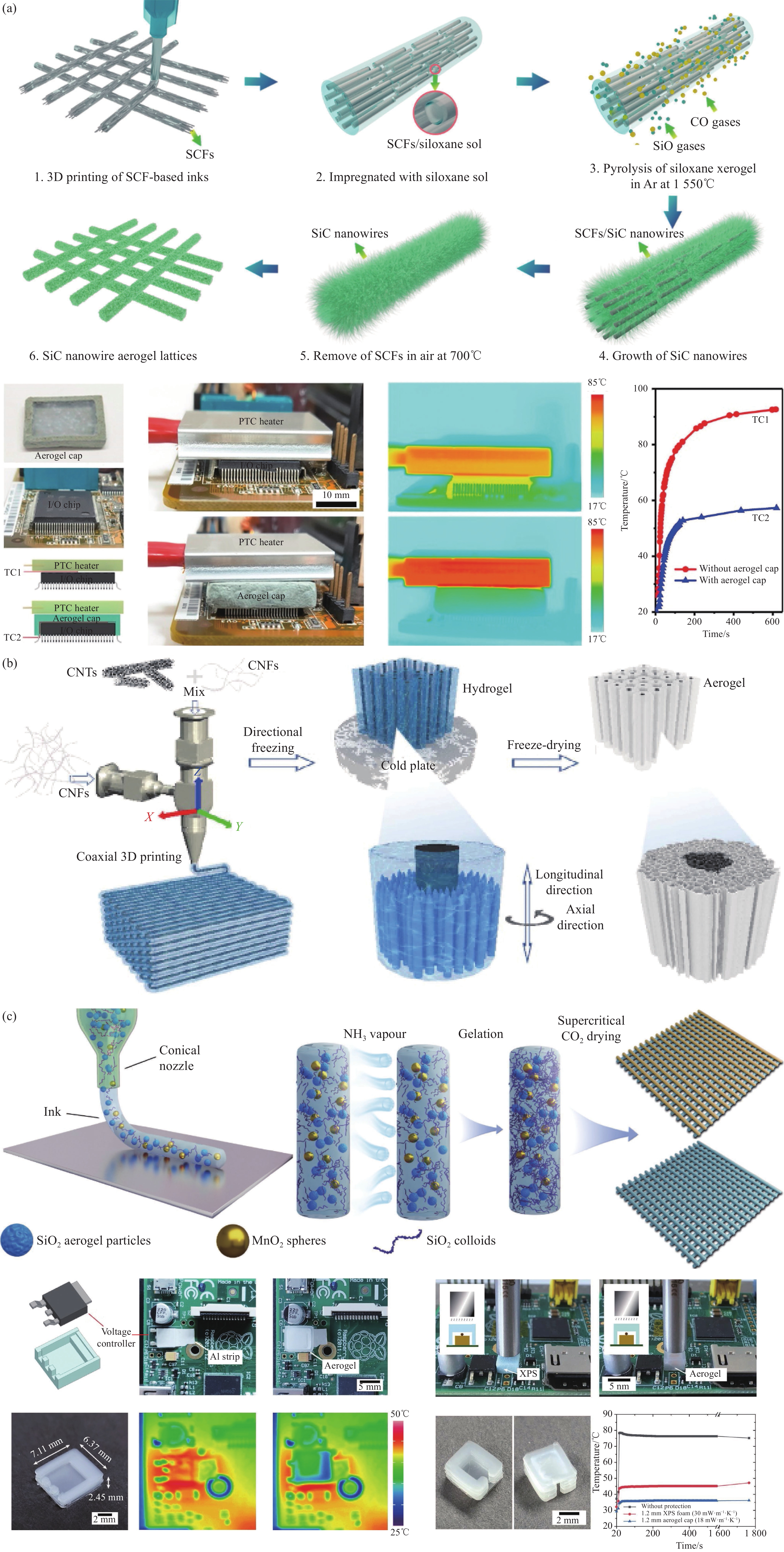
图 10 (a) 直接书写法制备SiC纳米线气凝胶及热学性测试[75]; (b) 冷冻法制备碳纳米管/纤维素纳米纤维水凝胶[76]; (c) 交联增稠法打印SiO2气凝胶及隔热应用[77]
Figure 10. (a) process and thermal characterization of SiC nanowire aerogels by direct writing[75]; (b) process of carbon nanotube/cellulose nanofiber mixed hydrogel by freezing method[76]; (c) process and thermal insulation application of SiO2 aerogels by Crosslinking thickening method[77]
![]()
![]()
![]()
表 2 不同纤维增强二氧化硅气凝胶的热-力性能
Table 2 Thermo-mechanical properties of SiO2 aerogel after enhancement by different fiber.
Aerogel composition Mechanical
property/MPaThermal
conductivity/
(mW·m−1·K−1)Ref. SiO2 0.01 0.030 [16] SiO2/Carbon Nanotubes 0.20 0.031 [24] SiO2/Graphene oxide 0.65 0.018 [25] SiO2/cellulose nanofibril 0.12 0.023 [26] SiO2/Quartz fiber 1.24 0.033 [27] SiO2/Glass fiber 1.34 0.021 [28] SiO2/Zr2O2 fiber 0.17 0.032 [29] SiO2/Aramid fiber 0.14 0.022 [30] SiO2/Blown foam 0.31 0.012 [31]  下载: 导出CSV
表 3 不同打印方式对比
Table 3 Comparison of 3D printing methods
Printing methods Description Characteristics Extrusion-based printing Preparing the ink with appropriate viscosity firstly, and form the required 3D structure layer by layer by means of nozzle extrusion. 1.Various shapes printable.
2.Low equipment cost.Light-based printing Using photo-curable resin to cure layer by layer to form a 3D structure by ultraviolet or visible light in the presence of a photoinitiator. 1.Usually short curing time and relatively high efficiency.
2.High printing accuracy.3D printed templating Using 3D printed resin as a template or mould. After injecting sol,
the template is removed by dissolution or pyrolysis to form a 3D structure1.No special requirements for sol control.
2.Suitable for traditional molecule-derived sols.
下载: 导出CSV
表 4 不同类别的阻燃气凝胶性能对比
Table 4 Comparison of the performance of different types of insulating aerogel
Category types Advantages Disadvantages Inorganic aerogel Oxidation aerogels, Nitride aerogels, Carbide aerogels. Low density, low thermal conductivity, high porosity Insufficient mechanical properties, deformation at high temperatures organic aerogel Cellulose aerogel, polyimide aerogel Good mechanics and abundant raw materials Poor high temperature resistance, easy aging, poor durability organic - inorganic composite aerogel Binary and multi-component composite aerogels, composite aerogels with substrates Balancing mechanical properties and flame retardancy, Integrated versatility Low porosity and high density
下载: 导出CSV
-
[1] KISTLER S. Coherent Expanded Aerogels and Jellies[J]. Nature, 1931, 127: 741.
[2] LI D C, CHEN Z F, DONG W F, et al. A review of silicon-based aerogel thermal insulation materials: Performance optimization through composition and microstructure[J]. Journal of Non-Crystalline Solids, 2020, 553: 120517.
[3] CAO L T, SHAN H R, ZONG D D, et al. Fire-Resistant and Hierarchically Structured Elastic Ceramic Nanofibrous Aerogels for Efficient Low-Frequency Noise Reduction[J]. Nano letters, 2022, 22: 1609. DOI: 10.1021/acs.nanolett.1c04532
[4] WEI J X, QUE Y S, ZHAO C X, et al. Colloids and Surfaces[J]. A: Physicochemical and Engineering Aspects, 2024, 683: 133047. DOI: 10.1016/j.colsurfa.2023.133047
[5] 宋晓颖, 刘敬肖, 史非, 等. CsxWO3/SiO2复合气凝胶的结构调控及其吸附/光催化性能[J]. 大连工业大学学报, 2022, 1: 41. SONG X Y, LIU J X, SHI F, et al. Structural control and adsorption/photocatalytic performance of CsxWO3/SiO2 composite aerogels[J]. Journal of Dalian Polytechnic University, 2022, 1: 41(in chinese).
[6] FERREIRA-Gonalves T, CONSTANTIN C, NEAGU M, et al. Safety and efficacy assessment of aerogels for biomedical applications[J]. Biomedicine & pharmacotherapy, 2021, 144: 112356.
[7] RAMASUBBU V, KUMAR P, MOTHI E, et al. Highly interconnected porous TiO2-Ni-MOF composite aerogel photoanodes for high power conversion efficiency in quasi-solid dye-sensitized solar cells[J]. Applied Surface Science, 2019, 496: 143646. DOI: 10.1016/j.apsusc.2019.143646
[8] LI Y, LIU X F, NIE X Y, et al. Multifunctional Organic–Inorganic Hybrid Aerogel for Self-Cleaning, Heat-Insulating, and Highly Efficient Microwave Absorbing Material[J]. Adv. Funct. Mater, 2019, 29: 1807624. DOI: 10.1002/adfm.201807624
[9] FENG J Z, SU B L, XIA H S, et al. Printed aegrogels: chemistry, processing, and applications[J]. Chemical Society Reviews, 2020, 50: 3842.
[10] AEGERTER M, LEVENTIS N, KOEBEL M. Aerogels Handbook[J]. Springer, 2011, pp: 155-170.
[11] AI D, ZHOU B, ZHANG Z H, et al. A Special Material or a New State of Matter: A Review and Reconsideration of the Aerogel[J]. Materials, 2013, 6: 941. DOI: 10.3390/ma6030941
[12] LI Z, CHENG X D, GONG L L, et al. Enhanced flame retardancy of hydrophobic silica aerogels by using sodium silicate as precursor and phosphoric acid as catalyst[J]. Journal of Non-Crystalline Solids, 2017, 481: 267.
[13] WAGLE R, YOO J. Preparation of highly porous Al2O3 aerogel by one-step solvent-exchange and ambient-pressure drying[J]. International Journal of Applied Ceramic Technology, 2020, 17: 1201. DOI: 10.1111/ijac.13455
[14] LIU B X, GAO M, LIU X C, et al. Monolithic zirconia aerogel from polyacetylacetonatozirconium precursor and ammonia hydroxide gel initiator: formation mechanism, mechanical strength and thermal properties[J]. RSC Advances, 2018, 8: 41603. DOI: 10.1039/C8RA08263D
[15] LINHARES T, PESSOA De Amorim M, DURãES L. Silica aerogel composites with embedded fibres: a review on their preparation, properties and applications[J]. Journal of Materials Chemistry A, 2019, 7: 22768. DOI: 10.1039/C9TA04811A
[16] HÜSING N, SCHUBERT U. Aerogels—Airy Materials: Chemistry, Structure, and Properties[J]. Angew Chem, 1998, 37: 22-45. DOI: 10.1002/(SICI)1521-3773(19980202)37:1/2<22::AID-ANIE22>3.0.CO;2-I
[17] ZHANG S, ZHAO D, Aerospace Materials Handbook [M]. CRC Press, 2013, pp: 699-743.
[18] BODAY D J, MURIITHI B, STOVER R J, et al. Polyaniline nanofiber–silica composite aerogels[J]. Non-Cryst. Solids, 2012, 358: 1575. DOI: 10.1016/j.jnoncrysol.2012.04.020
[19] RIFFAT S, QIU G, A review of state-of-the-art aerogel applications in buildings[J]. International Journal of Low-Carbon Technologies, 2013, 8: 1.
[20] HAYASE G, KUGIMIYA K, OGAWA M, et al. The thermal conductivity of polymethylsilsesquioxaneaerogels and xerogels with varied pore sizes for practical application as thermalsuperinsulators[J]. Journal of Materials Chemistry A, 2014, 2: 6525. DOI: 10.1039/C3TA15094A
[21] LIU H L, CHU P, LI H Y, et al. Novel three-dimensional halloysite nanotubes/silicacomposite aerogels with enhanced mechanical strength and low thermal conductivity prepared at ambient pressure[J]. Journal of Sol-Gel Science and Technology, 2016, 80: 651. DOI: 10.1007/s10971-016-4154-5
[22] HE J, ZHAO H, Li X, et al. Large-scale and ultra-low thermal conductivity of ZrO2 fibrofelt/ZrO2-SiO2 aerogels composites for thermal insulation[J]. Ceramics International, 2018, 44: 8742. DOI: 10.1016/j.ceramint.2018.01.089
[23] 于慧君. Al2O3-SiO2气凝胶复合材料中增强纤维表面结构设计与性能研究 [D]. 天津: 天津大学, 2021. YU H J. Surface structure design and properties of fibers to reinforce Al2O3-SiO2 aerogel composites [D]. Tianjin: Tianjin University, 2021(in Chinese).
[24] LAMY-MENDES A, GIRãO A V, SILVA R F, et al. Advances in carbon nanostructure–silica aerogel composites: a review[J]. Microporous and Mesoporous Materials, 2019, 288: 109575. DOI: 10.1016/j.micromeso.2019.109575
[25] LIU H L, HE X A, LI H Y, et al. Novel GO/silica composite aerogels with enhanced mechanical and thermal insulation properties prepared at ambient pressure[J]. Ferroelectrics, 2018, 528(1): 15. DOI: 10.1080/00150193.2018.1448192
[26] CHEN Y X, SEPAHVAND S, GAUVIN F, et al. One-pot synthesis of monolithic silica-cellulose aerogel applying a sustainable sodium silicate precursor[J]. Construction and Building Materials, 2021, 293: 123289. DOI: 10.1016/j.conbuildmat.2021.123289
[27] 王衍飞, 张长瑞, 冯坚, 等. 纤维增强Al2O3-SiO2气凝胶隔热复合材料研究进展[J]. 硅酸盐学报, 2009, 37(2): 234-237. WANG Y F, ZHANG C R, FENG J, et al. Research Progress on Fiber Reinforced Alumina-Silica Aerogel Thermal Insulation Composites[J]. Journal of the Chinese Ceramic Society, 2009, 37(2): 234-237(in Chinese).
[28] ZHOU T, CHENG X D, PAN Y L, et al. Mechanical performance and thermal stability of glass fiber reinforced silica aerogel composites based on co-precursor method by freeze drying[J]. Applied Surface Science, 2018, 437: 321-328. DOI: 10.1016/j.apsusc.2017.12.146
[29] HE J, ZHAO H Y, LI X L, et al. Large-scale and ultra-low thermal conductivity of ZrO2 fibrofelt/ZrO2-SiO2 aerogels composites for thermal insulation[J]. Ceramics International, 2018, 44(8): 8742. DOI: 10.1016/j.ceramint.2018.01.089
[30] LI Z, CHENG X D, HE S, et al. Aramid fibers reinforced silica aerogel composites with low thermal conductivity and improved mechanical performance[J]. Composites Part A: Applied Science and Manufacturing, 2016, 84: 316-325. DOI: 10.1016/j.compositesa.2016.02.014
[31] MERILLAS B, Lamy-Mendes A, Villafañe F, et al. Research progress on mechanical properties enhancement of SiO2 aerogels[J]. Materials Today Chemistry, 2022, 26: 101257. DOI: 10.1016/j.mtchem.2022.101257
[32] MOHANAN J, BROCK S. A new addition to the aerogel community: unsupported CdS aerogels with tunable optical properties[J]. Journal of Non-Crystalline Solids, 2004, 350: 1. DOI: 10.1016/j.jnoncrysol.2004.05.020
[33] ZIEGLER C, WOLF A, LIU W, et al. Modern Inorganic Aerogels[J]. Angewandte Chemie, 2017, 56: 13200. DOI: 10.1002/anie.201611552
[34] ZIEGLER C, KLOSZ S, BORCHARDT L, et al. ZnPd/ZnO Aerogels as Potential Catalytic Materials[J]. Advanced Functional Materials, 2016, 26: 1014. DOI: 10.1002/adfm.201503000
[35] MOHANAN J, ARACHCHIGE I, BROCK S. Porous semiconductor chalcogenide aerogels[J]. Science, 2005, 307: 397. DOI: 10.1126/science.1104226
[36] LI M M, CHEN X, LI X T, et al. Controllable Strong and Ultralight Aramid Nanofiber-Based Aerogel Fibers for Thermal Insulation Applications[J]. Advanced Fiber Materials, 2022, 4: 1267. DOI: 10.1007/s42765-022-00175-2
[37] BARRON A, NIEDERBERGER M, COLBEAU-JUSTIN C, et al. Monolithic metal-containing TiO2 aerogels assembled from crystalline pre-formed nanoparticles as efficient photocatalysts for H2 generation[J]. Applied Catalysis B: Environmental, 2020, 267: 118660. DOI: 10.1016/j.apcatb.2020.118660
[38] KORALA L, LI L, BROCK S. Transparent conducting films of CdSe(ZnS) core(shell) quantum dot aerogels[J]. Chemical Communications, 2012, 48: 8523. DOI: 10.1039/c2cc34188c
[39] ZHANG X X, CHENG X T, Si Y, et al. Elastic and highly fatigue resistant ZrO2-SiO2 nanofibrous aerogel with low energy dissipation for thermal insulation[J]. Chemical engineering journal, 2022, 433: 133628. DOI: 10.1016/j.cej.2021.133628
[40] HAN X S, WU W J, TIAN Z W, et al. “Top-down” fabrication of anisotropic, lightweight, super-amphiphobic, and thermal insulating rattan aerogels[J]. Composites Communications, 2022, 33: 101199 DOI: 10.1016/j.coco.2022.101199
[41] LIU Z W, LYU J, FANG D, et al. Nano fibrous Kevlar Aerogel Threads for Thermal Insulation in Harsh Environments[J]. ACS nano, 2019, 13: 5703. DOI: 10.1021/acsnano.9b01094
[42] HU Y H, YANG G, ZHOU J T, et al. Proton Donor-Regulated Mechanically Robust Aramid Nanofiber Aerogel Membranes for High-Temperature Thermal Insulation[J]. ACS Nano, 2022, 16: 5984. DOI: 10.1021/acsnano.1c11301
[43] HU P Y, LYU J, FU C, et al. Multifunctional Aramid Nanofiber/Carbon Nanotube Hybrid Aerogel Films[J]. ACS nano, 2020, 14: 688.
[44] WANG S J, MENG W Y, LV H F, et al. Thermal insulating, light-weight and conductive cellulose/aramid nanofibers composite aerogel for pressure sensing[J]. Carbohydrate Polymers, 2021, 28: 118414.
[45] HAO X. MOF-derived Co@C nanoparticle anchored aramid nanofiber (ANF) aerogel for superior microwave absorption capacity[J]. RSC Adv, 2021, 42: 26319.
[46] WANG F, WU Y D, JIN M M, et al. Insights into the Prospective Aerogel Scaffolds Composed of Chitosan/Aramid Nanofibers for Tissue Engineering[J]. ACS Applied Polymer Matterial, 2022, 4: 4643. DOI: 10.1021/acsapm.1c01862
[47] SONG L M, FAN B B, CHEN Y Q, et al. Ultralight and hyperelastic SiC nanofiber aerogel spring for personal thermal energy regulation[J]. Journal of Advanced Ceramics, 2022, 11: 1235. DOI: 10.1007/s40145-022-0606-2
[48] QIN H F, ZHANG Y F, JIANG J G, et al. Multifunctional Superelastic Cellulose Nanofibrils Aerogel by Dual Ice-Templating Assembly[J]. Advanced Functional Materials, 2021, 31: 2106269. DOI: 10.1002/adfm.202106269
[49] WANG W Y, ZHAO X W, LIN Y. Self-Assembled Construction of Robust and Super Elastic Graphene Aerogel for High-Efficient Formaldehyde Removal and Multifunctional Application[J]. Small, 2023, 19: 2300234. DOI: 10.1002/smll.202300234
[50] LI Y, ZHANG X T. Electrically conductive, optically responsive, and highly orientated Ti3C2Tx MXene aerogel fibers[J]. Advanced Functional Materials, 2021, 32: 2107767.
[51] TIAn R, JIA X H, HUANG C Y, et al. Flexible, Flame-Resistant, and Anisotropic Thermally Conductive Aerogel Films with Ionic Liquid Crystal-Armored Boron Nitride[J]. ACS Applied Materials & Interfaces, 2023, 15: 27223.
[52] DU Y Q, XU J, FANG J F, et al. Ultralight, highly compressible, thermally stable MXene/aramid nanofiber anisotropic aerogels for electromagnetic interference shielding[J]. Journal of Materials Chemistry A, 2022, 10: 6690. DOI: 10.1039/D1TA11025J
[53] SONG H F, KANG F Y. Recent Progress on Thermal Conduction of Graphene[J]. Acta Phys. -Chim. Sin, 2022, 38(1).
[54] LIU X Y, YANG J Y, WANG J Y, et al. MXene-modified silicone rubber composites with high thermal stability: Preparation and properties[J]. Materials Letters, 2021, 34: 130639.
[55] ZHANG E S, ZHANG W L, LV T, et al. Insulating and Robust Ceramic Nanorod Aerogels with High-Temperature Resistance over 1400℃[J]. ACS Appl. Mater. Interfaces, 2021, 13: 20548. DOI: 10.1021/acsami.1c02501
[56] LIU F Q, HE C B, JIANG Y G, et al. Carbon layer encapsulation strategy for designing multifunctional core-shell nanorod aerogels as high-temperature thermal superinsulators[J]. Chemical Engineering Journal, 2023, 455: 140502. DOI: 10.1016/j.cej.2022.140502
[57] CAI B, ROMÁN-LESHKOV Y, AKKIRAJU K, et al. Solid-State Gelation for Nanostructured Perovskite Oxide Aerogels[J]. Chemistry of Materials, 2019, 22: 9422.
[58] ALIEV A, OH J, KOZLOV M, et al. Giant-Stroke, Superelastic Carbon Nanotube Aerogel Muscles[J]. Science, 2009, 323: 1565.
[59] LI Y L KINLOCH L, WINDLE A. Direction spinningof cabon nanotube fibers from chemical vapor deposition synthesis[J]. Science, 2004, 304: 276. DOI: 10.1126/science.1094982
[60] KANG T, KIM Y, IM H, et al. High-efficiency electrochemical thermal energy harvester using carbon nanotube aerogel sheet electrodes[J]. Nature Communications, 2016, 7: 10600. DOI: 10.1038/ncomms10600
[61] DU A, WANG H Q, ZHOU B, et al. Multifunctional silica nanotube aerogels (SNTAs) inspired by polar bear hair for light management and thermal insulation[J]. Chemistry of Materials, 2018, 30: 6849. DOI: 10.1021/acs.chemmater.8b02926
[62] XU X, ZHANG Q Q, HAO M L, et al. Double-negative-index ceramic aerogels for thermal superinsulations[J]. Science, 2019, 363: 723. DOI: 10.1126/science.aav7304
[63] CHENG X T, SI Y, YU J Y, et al. Direct synthesis of highly stretchable ceramic nanofibrous aerogels via 3D reaction electrospinning[J]. Nature Communications, 2021, 13: 2637.
[64] DUAN X F, Li H, Xu X, et al. Hypocrystalline ceramic aerogels for thermal insulation at extreme conditions[J]. Nature, 2021, 42: 909.
[65] HUANG T, ZHU Y, ZHU J, et al. Self-reinforcement of Light, Temperature-Resistant Silica Nanofibrous Aerogels with Tunable Mechanical Properties[J]. Advanced Fiber Materials, 2020, 2: 338. DOI: 10.1007/s42765-020-00054-8
[66] SPADACCINI C, WORSLEY M, ZHU C, et al. Highly compressible 3D periodic graphene aerogel microlattices[J]. Nature Communications, 2015, 6: 1.
[67] GARCÍA-TORRES B, AGUILAR-ELGUEZABAL A, ROMÁN-AGUIRRE M, et al. Synthesis of silica aerogels microspheres prepared by ink jet printing and dried at ambient pressure without surface hydrophobization[J]. Materials Chemistry & Physics, 2016, 172: 32.
[68] 姚利萍, 吴明华, 李超. SiO2气凝胶微球的制备及其在织物隔热涂层中的应用[J]. 浙江理工大学学报, 2023, 49: 431. YAO L P, WU M H, LI C. Preparation of SiO2 aerogel microspheres and their application in thermal insulation coatings of fabrics[J]. Journal of Zhejiang sci-tech university, 2023, 49: 431(in chinese).
[69] POLDSALU I, JOHANSON U, TAMM T, et al. Mechanical and electro-mechanical properties of EAP actuators with inkjet printed electrodes[J]. Synthetic Metals, 2018, 246: 122. DOI: 10.1016/j.synthmet.2018.10.009
[70] SOMALU M, MUCHTAR A, DAUD W, et al. Screen-printing inks for the fabrication of solid oxide fuel cell films: A review[J]. Renewable and Sustainable Energy Reviews, 2017, 75: 246.
[71] TUO X L, YANG S X, XIE C J, et al. The Aramid-Coating-on-Aramid Strategy toward Strong, Tough, and Foldable Polymer Aerogel Films[J]. ACS Nano, 2022, 16: 14334. DOI: 10.1021/acsnano.2c04572
[72] YANG S X, QIU T, XIE C J, et al. The Aramid-Coating-on-Aramid Strategy toward Strong, Tough, and Foldable Polymer Aerogel Films[J]. ACS Nano, 2022, 16: 14334-14343. DOI: 10.1021/acsnano.2c04572
[73] WANG B L, Li G Y, Xu L, et al. Nanoporous Boron Nitride Aerogel Film and Its Smart Composite with Phase Change Materials[J]. ACS Nano, 2020, 14: 16590. DOI: 10.1021/acsnano.0c05931
[74] KOO J, KIM J, KIM M, et al. Inkjet Printing of Silica Aerogel for Fabrication of 2-D Patterned Thermal Insulation Layers[J]. International Journal of Precision Engineering and Manufacturing-Green Technology, 2020, 8: 445.
[75] GUO P F, SU L, PENG K, et al. Additive manufacturing of resilient SiC nanowire aerogels[J]. ACS nano, 2022, 16: 6625. DOI: 10.1021/acsnano.2c01039
[76] WANG F, YANG Z J, HU X Z, et al. Coaxial 3D printed anisotropic thermal conductive composite aerogel with aligned hierarchical porous carbon nanotubes and cellulose nanofibers[J]. Smart Materials & Structures, 2022, 31: 45002.
[77] ZHAO S, SIQUEIRA G, DRDOVA S, et al. Additive manufacturing of silica aerogels[J]. Nature, 2020, 584: 387. DOI: 10.1038/s41586-020-2594-0
[78] WANG L K, FENG J Z, ZHANG S Y, et al. Dual-channel coextrusion printing strategy towards mechanically enhanced, flame retardant, and thermally stable polyimide-silica aerogels for thermal insulation[J]. Additive Manufacturing, 2023, 71: 103583. DOI: 10.1016/j.addma.2023.103583
[79] MELCHELS F, JAN F, GRIJPMA D. A review on stereolithography and its applications in biomedical engineering[J]. Biomaterials, 2010, 31: 6121. DOI: 10.1016/j.biomaterials.2010.04.050
[80] WHITE L, SELDEN T, BERTINO M, et al. Fabrication of mechanically strong honeycombs with aerogel cores[J]. Industrial & Engineering Chemistry Research, 2018, 57: 1197.
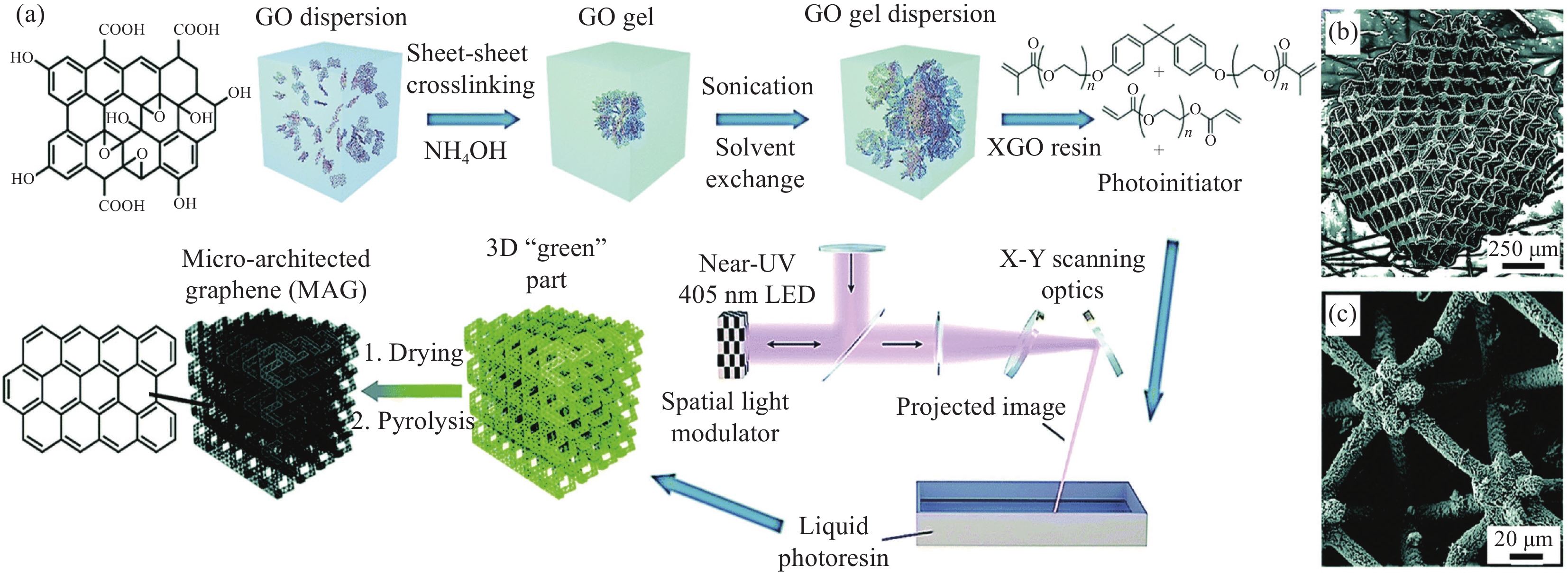
[81] HENSLEIGH R, HUA C, OAKDALE J, et al. Additive manufacturing of complex micro-architected graphene aerogels[J]. Materials Horizons, 2018, 5: 1035. DOI: 10.1039/C8MH00668G
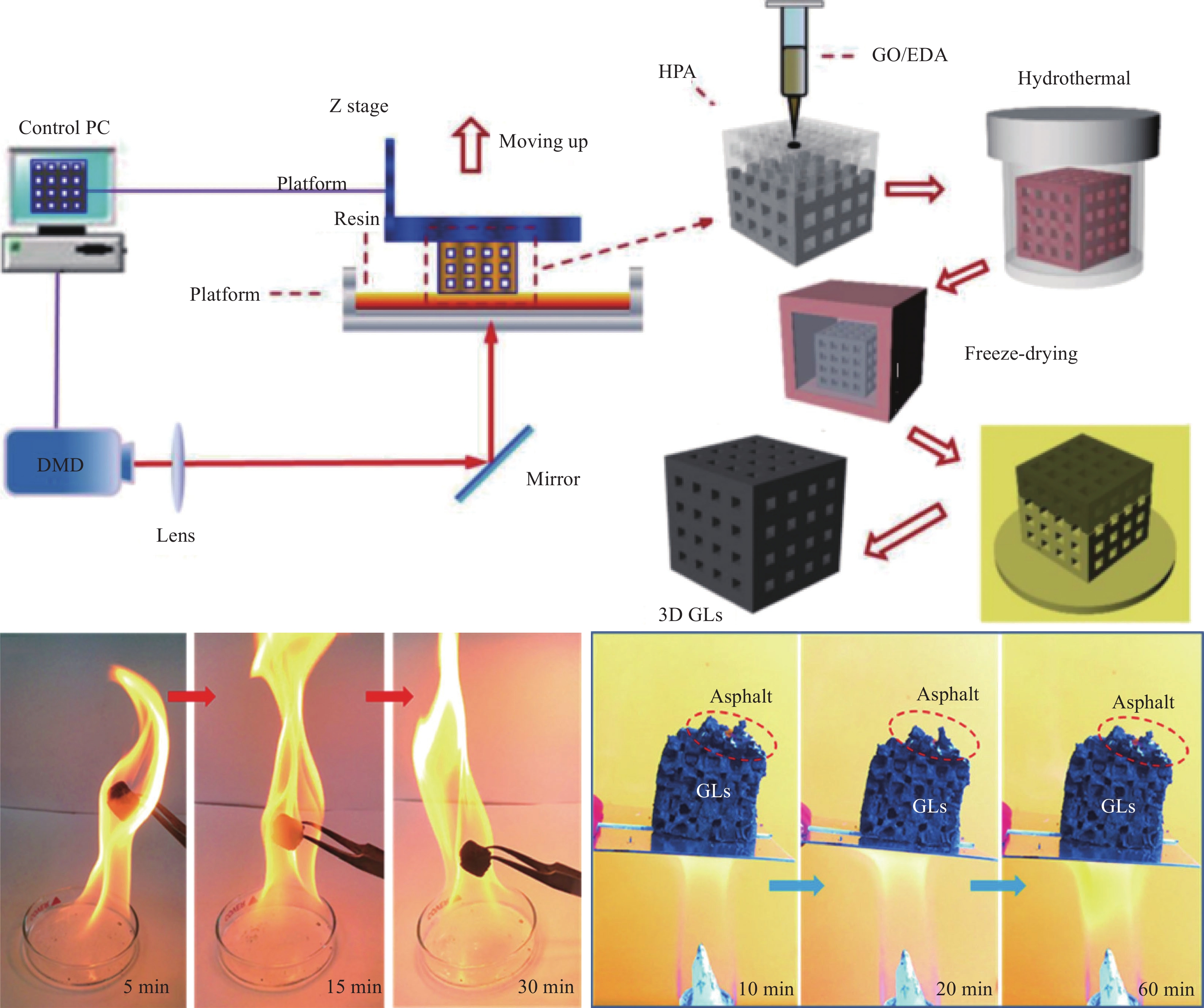
[82] ZHANG Q Q, ZHANG F, XU X, et al. Three-Dimensional Printing Hollow Polymer Template-Mediated Graphene Lattices with Tailorable Architectures and Multifunctional Properties[J]. ACS Nano, 2018, 12: 1096. DOI: 10.1021/acsnano.7b06095
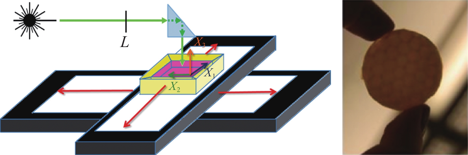
[83] WANG J, YUAN D S, HU P Y, et al. Optical design of silica aerogels for on-demand thermal management[J]. Advanced Functional Materials, 2023, 33: 2300441. DOI: 10.1002/adfm.202300441
[84] WAGLE R, YOO J. Preparation of highly porous Al2O3 aerogel by one-step solvent-exchange and ambient-pressure drying[J]. International Journal of Applied Ceramic Technology, 2020, 17: 1201. DOI: 10.1111/ijac.13455
[85] WU Z G, ZHAO Y X, XU L P, et al. Preparation of zirconia aerogel by heating of alcohol-aqueous salt solution[J]. Journal of Non-Crystalline Solids, 2003, 330: 274. DOI: 10.1016/j.jnoncrysol.2003.08.049
[86] ZHANG X X, WANG F, DOU L, et al. Ultrastrong, Superelastic, and Lamellar Multiarch Structured ZrO2–Al2O3 Nanofibrous Aerogels with High-Temperature Resistance over 1300℃[J]. ACS Nano, 2020, 14: 15616. DOI: 10.1021/acsnano.0c06423
[87] Liu B X, GAO M, LIU X C, et al. Thermally Stable Nanoporous ZrO2/SiO2 Hybrid Aerogels for Thermal Insulation[J]. ACS Applied Nano Materials, 2019, 11: 7299.
[88] DONG S, MACIEJEWSKA B, MILLAR R, et al. 3D Electrospinning of Al2O3/ZrO2 fibrous aerogels for multipurpose thermal insulation[J]. Adv Compos Hybrid Mater, 2023, 6: 186. DOI: 10.1007/s42114-023-00760-y
[89] SCHERER G. Viscous sintering with a pore-size distribution and rigid inclusions[J]. Journal of the American Ceramic Society, 1988, 10: 447.
[90] FUKUI T, HORI M. Thermal stability of aluminas by hydrothermal treatment of an alkoxide-derived gel[J]. Journal of materials science, 1995, 30: 1794. DOI: 10.1007/BF00351612
[91] CAI H F, JIANG Y G, CHEN Q, et al. Sintering behavior of SiO2 aerogel compositesreinforced by mullite fibers via in-situ rapid heating TEM observations[J]. Journal of the European Ceramic Society, 2020, 40: 127. DOI: 10.1016/j.jeurceramsoc.2019.09.014
[92] XIONG R, LI X L, JI H, Thermal stability of ZrO2-SiO2 aerogel modified by Fe (III) ion[J]. Journal of Sol-Gel Science and Technology, 2014, 72: 496.
[93] ZU G Q, SHEN J, WANG W Q, et al. Robust, highly thermally stable, core-shell nanostructured metal oxide aerogels as high-temperature thermal superinsulators, Adsorbents, and Catalysts[J]. Chemistry of Materials, 2014, 26: 5761. DOI: 10.1021/cm502886t
[94] HE J, LI X L, SU D, Super-hydrophobic hexamethyl-disilazane modifiedZrO2-SiO2 aerogels with excellent thermal stability[J]. Journal of Materials Chemistry, 2016, 4: 5632.
[95] ZHAO H Y, LI X L, HE J, et al. Improvement of Thermal Stability of ZrO2-SiO2 Aerogel Modified by Ca(II) Cations[J]. Solid State Phenomena, 2018, 281: 105. DOI: 10.4028/www.scientific.net/SSP.281.105
[96] PENG F, JIANG Y G, FENG J Z, et al. A facile method to fabricate monolithic alumina–silica aerogels with high surface areas and good mechanical properties[J]. Journal of the European Ceramic Society, 2020, 40: 2480. DOI: 10.1016/j.jeurceramsoc.2020.01.058
[97] HU Z P, HE J, LI X L, et al. Improvement of thermal stability of ZrO2–SiO2 aerogels by an inorganic–organic synergetic surface modification[J]. Journal of Porous Materials, 2017, 24: 657. DOI: 10.1007/s10934-016-0302-0
[98] VAZHAYAL L, WILSON P, PRABHAKARAN K. Waste to wealth: Lightweight, mechanically strong and conductive carbon aerogels fromWaste tissue paper for electromagnetic shielding and CO2 adsorption[J]. Chemical Enginneering Journal, 2020, 381: 122628. DOI: 10.1016/j.cej.2019.122628
[99] WANG Z J, DAI D, LAN X L, et al. Designed fabrication of lightweight SiC/Si3N4 aerogels for enhanced electromagnetic wave absorption and thermal insulation[J]. Journal of Alloys and Compounds, 2022, 901: 163651. DOI: 10.1016/j.jallcom.2022.163651
[100] LIU D B, XUE Y H. Preparation and structure of silicon oxycarbide aerogels fabricated by polymer derived ceramics method[J]. Journal of Porous Materials, 2022, 30: 881.
[101] CUI S, SUO H, JING F, et al. Facile preparation of ZrCO composite aerogel with high specific surface area and low thermal conductivity[J]. Journal of Sol-Gel Science and Technology, 2018, 86: 383. DOI: 10.1007/s10971-018-4638-6
[102] KONG Y, ZHONG Y, SHEN X D, et al. Effect of silica sources on nanostructures of resorcinol–formaldehyde/silica and carbon/silicon carbide composite aerogels[J]. Microporous Mesoporous Materials, 2014, 197: 77. DOI: 10.1016/j.micromeso.2014.05.032
[103] YU Z L, YANG N, QIN B, et al. Fire-Retardant and Thermally Insulating Phenolic-Silica Aerogels[J]. Angew. Chem, 2018, 57: 4538. DOI: 10.1002/anie.201711717
[104] CHENG H M, FAN Z H, HONG C Q, et al. Lightweight multiscale hybrid carbon-quartz fiber fabric reinforced phenolic-silica aerogel nanocomposite for high temperature thermal protection[J]. Composites Part A, 2021, 143: 106313. DOI: 10.1016/j.compositesa.2021.106313
[105] LIU H, TIAN Y, JIAO J H, et al. Thermal conductivity modeling of hollow fiber-based porous structures for thermal insulation applications[J]. Non-Cryst Solids, 2022, 575: 121188. DOI: 10.1016/j.jnoncrysol.2021.121188
[106] LU W, CHUNG D. Oxidation protection of carbon materials by acid phosphate impregnation[J]. Carbon, 2002, 40: 1249. DOI: 10.1016/S0008-6223(01)00297-4
[107] ZHUANG L, LU D, ZHANG J J, et al. Highly cross-linked carbon tube aerogels with enhanced elasticity and fatigue resistance[J]. Nature Communications, 2023, 14: 3178. DOI: 10.1038/s41467-023-38664-6
[108] ZENG X L, YE L, SUN S, et al. Observation of viscoelasticity in boron nitride nanosheet aerogel[J]. Physical Chemistry Chemical Phy, 2015, 17: 16709. DOI: 10.1039/C5CP02192H
[109] SONG Y X, LI B, YANG S W, et al. Ultralight boron nitride aerogels via template-assisted chemical vapor deposition[J]. Scientific Reports, 2015, 5: 10337. DOI: 10.1038/srep10337
[110] BERNARD S, MIELE P. Nanostructured and architectured boron nitride from boron, nitrogen and hydrogen-containing molecular and polymeric precursors[J]. Materials Today, 2014, 17: 443. DOI: 10.1016/j.mattod.2014.07.006
[111] YANG H X, LI C M, YUE X D, et al. New BN/SiOC aerogel composites fabricated by the sol-gel method with excellent thermal insulation performance at high temperature[J]. Materials & Design, 2020, 185: 108217.
[112] DING J, WU X D, SHEN X D, et al. Synthesis and textural evolution of mesoporous Si3N4 aerogel with high specific surface area and excellent thermal insulation property via the urea assisted sol-gel technique[J]. Chemical Engineering Journal, 2019, 382: 122880.
[113] OUYANG T, CHEN Y P, XIE Y. Thermal transport in hexagonal boron nitride nanoribbons[J]. Nano technology, 2010, 21: 245701.
[114] ZHU M Y, LI G Y, GONG W B, et al. Calcium-Doped Boron Nitride Aerogel Enables Infrared Stealth at High Temperature Up to 1300℃[J]. Nano-Micro Letters, 2022, 14: 12. DOI: 10.1007/s40820-021-00755-8
[115] APOSTOLOPOULOU V, MUNIER P, BERGSTRöM L. Thermally Insulating Nanocellulose-Based Materials[J]. Advanced Materials, 2020, 33: 2001839.
[116] SHEN D K, GU S. Corrigendum to “The mechanism for thermal decomposition of cellulose and its main products”[J]. Bioresource Technology, 2010, 101: 6879. DOI: 10.1016/j.biortech.2010.04.002
[117] ZHOU S Y, KALKAVOURA V, XU C. Elastic aerogels of cellulosenanofibers@metal-organic frameworks for thermal insulation and fire retardancy[J]. Nano-Micro Letters, 2020, 12: 102. DOI: 10.1007/s40820-020-00432-2
[118] AHANKARI S, PALIWAL P, SUBHEDAR A. Recent developments in nanocellulose-based aerogels in thermal applications: A review[J]. ACS Nano, 2021, 15: 3849. DOI: 10.1021/acsnano.0c09678
[119] CHIDAMBARESWARAPATTAR C, LARIMORE Z, SOTIRIOU-LEVENTIS C, et al. One-step room-temperature synthesis of fibrous polyimide aerogels from anhydrides and isocyanates and conversion to isomorphic carbons[J]. Journal of Materials Chemistry, 2010, 20: 9666-9678. DOI: 10.1039/c0jm01844a
[120] CHEN Z L, CHEN J, HOU X B, et al. Mechanically robust and thermal-insulated polyimide aerogel films by polymerization-regulated strategy for flexible thermal protection[J]. Chemical Engineering Journal, 2024, 496: 154251. DOI: 10.1016/j.cej.2024.154251
[121] WANG S, DING R D, LIANG G Q, et al. Direct Synthesis of Polyimide Curly Nanofibrous Aerogels for High-Performance Thermal Insulation Under Extreme Temperature[J]. Advanced Materials, 2024, 36: 2313444. DOI: 10.1002/adma.202313444
[122] CHEN Y, SHI B L, JIN R Z, et al. Ultralight, low-shrinkage copolyimide aerogels with excellent mechanical strength for flexible thermal protection[J]. Chemical Engineering Journal, 2024, 497: 154353. DOI: 10.1016/j.cej.2024.154353
[123] HAN L J, CHEN S L, LI H H, et al. Rapid and inexpensive synthesis of liter-scale SiC aerogels[J]. nature communications, 2024, 15: 6959. DOI: 10.1038/s41467-024-51278-w
[124] HONG X S, ZHENG Y Y, SHI Y Q, et al. A Facile strategy for constructing lightweight, fire Safety and compression resistance poly(vinylalcohol) aerogels with highly-efficient expansible graphene oxide/Layered double hydroxides hybrid synergistic flame retardant[J]. Journal of Colloid and Interface Science, 2023, 650: 686-700. DOI: 10.1016/j.jcis.2023.07.028
[125] OMRANPOUR H, HASSANIFARD S, MONFARED A. R, et al. Advanced, universal, and facile gel spinning-based aerogel fibrillation: in situ fabrication of highly stretchable TPU-silica hybrid network in ambient conditions[J]. Adv Compos Hybrid Mater, 2024, 7: 105. DOI: 10.1007/s42114-024-00911-9
[126] BERARDI U. The development of a monolithic aerogel glazed window for an energy retrofitting project[J]. APPLIED ENERGY -BARKING THEN OXFORD, 2015, 154(1): 603-615.
[127] WU M R, SHAO Z Y, BAI H, et al. Biomimetic, knittable aerogel fiber for thermal insulation textile[J]. Science, 2023, 382: 1379-1383. DOI: 10.1126/science.adj8013
[128] LIU Z J, RAN Y Y, XI J N, et al. Polymeric hybrid aerogels and their biomedical applications[J]. Soft Matter, 2020, 16: 9160. DOI: 10.1039/D0SM01261K
[129] HUANG H, CHEN P W, ZHANG X T, et al. Edge-to-Edge Assembled Graphene Oxide Aerogels with Outstanding Mechanical Performance and Superhigh Chemical Activi.[J]. Small, 2013, 9: 1397. DOI: 10.1002/smll.201202965
[130] WANG J, WANG J. Advances on Dimensional Structure Designs and Functional Applications of Aerogels[J]. Acta Chimica Sinica, 2021, 79: 430-442. DOI: 10.6023/A20110531
-
目的
由于气凝胶独特的三维纳米网络结构使其同时具有超低密度和超低热导率的特性,因而关于气凝胶的研究一直是热点领域,大量科研人员对此进行了很多研究工作,形成丰硕的研究成果。本工作通过对近些年气凝胶研究成果进行梳理总结,为其他想了解、学习气凝胶隔热前沿进展的科研人员提供借鉴,考虑到当前围绕气凝胶进展研究主要集中在功能、方法的区分,具体到隔热这一具体领域的研究较少,因此,本综述立足气凝胶的阻燃隔热应用,分析了气凝胶材料的制备方式,重点论述了溶胶-凝胶法、分子路线法、静电纺丝法、3D打印等方法并对气凝胶材料在隔热领域的应用进行了总结;后续又对气凝胶的材料选用等方面进行探讨,最后展望和分析气凝胶的未来研究重点方向。
方法本研究围绕气凝胶的阻燃隔热主题,采取定量分析和定性论述相结合的办法。由于气凝胶的隔热阻燃性能与气凝胶的结构和组成密切相关,而结构与制备方法存在直接联系,因而,从气凝胶的制备方法和材料2个方面论述了气凝胶在隔热阻燃方面的应用,并通过Citespace文献计量工具,利用分析关键词整理了气凝胶的隔热阻燃用的发展趋势和动向,进而总结了不同方法和材料的优缺点,最后展望了气凝胶未来研究重点。
结果纵然阻燃隔热用气凝胶制备方法和制备材料多种多样,但均存在缺点不足,达到商业化的成熟应用仍需进一步努力。在制备方法方面,溶胶-凝胶制备路线虽然技术简单且路径成熟,但气凝胶制备材料受限,且制备的气凝胶骨架结构仅通过纳米粒子相互连接,脆性大且易塌陷,需要增强工艺提升力学性能;纳米构筑单元组装法扩大了凝胶种类,优化了凝胶性能,实现对凝胶功能精准调控,但也是需要增强气凝胶力学性能;其他制备方法,诸如3D打印、静电纺丝等方式,存在加工效率低、制备成本高等缺点,需进一步优化制备设备、改进接收装置。在制备材料方面,包括无机气凝胶、有机气凝胶和通过多组分材料制备的无机/有机复合气凝胶3类,无机气凝胶虽然阻燃性好,但力学性需要改进提升;有机气凝胶与之相反,力学性能优异但高温易燃分解;进而提出无机/有机复合气凝胶制备路线,有效兼顾了力学-耐高温性能,但性能也需要进一步提升。
结论纵然气凝胶在阻燃隔热领域的研究取得了突破和发展,但距离产业化和商业化的应用仍存在差距,未来还需要开展更多工作。在此,本文提出关于阻燃隔热用气凝胶建设建议:一是进一步加强机理研究。探讨气凝胶的合成方法、孔隙形成机制、内部结构与其热-机械能之间的联系,为更好制备高性能气凝胶提供理论指导;二是开发新型纳米结构。当前,通过纳米构筑气凝胶的基础单元多为均匀结构,关于多孔结构或其它新型结构研究较少;且构筑单元的形貌、大小对气凝胶多孔结构的影响进而如何作用于阻燃隔热的研究较少;三是建立气凝胶阻燃评价体系。气凝胶阻燃隔热性能评价主要通过灼烧样品后观察结构完整性判断其性能。然而对其他性能,诸如力学性能、体积变化等无过多测试;四是研制集成多功能气凝胶。现代工业高速发展对材料的综合性能提出越来越高的要求,单一卓越性能的材料已难以满足市场需要,要充分利用气凝胶隔热阻燃性能的天然属性,开展交叉研究,研制多功能气凝胶,扩展在不同领域的应用性。诸如在建筑行业,开发透光隔热气凝胶,能够较普通玻璃减少50%以上的供暖能耗,降低光照强度;在纺织行业,针对高原寒区官兵对冬服御寒、抗菌、轻便的特殊需求,气凝胶纤维能够屏蔽人体热辐射、降低服装30%重量,另外赋予其抗菌功能,提升卫生性,更好保障高原官兵。五是如何精准控制气凝胶的孔洞结构、开发气凝胶双网络体系、研究快捷高效的干燥方法等将成为未来研究重点,对此大量的研究者也在积极探索,在制备方法、干燥方式以及材料研制上不断有新进展,以此提升气凝胶的综合性能和实现低成本简单的制备。我们相信,随着研究的不断深入,气凝胶将会推动现有领域的发展并可能创造新功能。


计量
- 文章访问数: 17
- HTML全文浏览量: 3
- PDF下载量: 5
