

Research progress and challenges in manufacturing fiber reinforced ceramic matrix composites using direct ink writing technology
-
摘要:
先进陶瓷及其复合材料凭借优异的性能已被广泛应用于航空航天领域,目前采用三维打印技术实现这类材料的快速低成本制备成为核心问题。与传统工艺相比,现有三维打印陶瓷材料普遍面临着脆性特征明显及损伤容限能低的问题,因此纤维复合陶瓷材料的三维打印技术成为研究热点。综述了近年来国内外基于墨水直写技术制备纤维强韧陶瓷基复合材料的技术路线及特点,围绕这类材料的组成成分、工艺路径与力学性能的关系,综合分析了不同陶瓷墨水的设计、纤维引入的方式、致密化工艺的选择、打印构件关键性能之间的有机联系,指出了当前的主要问题并对未来研究方向进行了展望。
Abstract:Advanced ceramics and composites have been widely used in aerospace applications because of their excellent performance, at present, the use of three-dimensional (3D) printing technology to achieve rapid, efficient, and low-cost preparation of such materials has become a central issue. Compared with the traditional process, the 3D printing of ceramic materials is generally faced with the problem of their inherent brittleness and low damage tolerance. Therefore, the incorporation of fiber reinforcements in printed parts to overcome the challenges of poor fracture toughness of advanced ceramics has become a hot topics and frontier. Here, this work systematically summarize recently developed direct ink writing (DIW) technologies for printing fiber reinforced ceramic matrix composites (FRCMC), focus on the relationship between the processing, structure, and properties of DIW-FRCMCs, comprehensively analyze the ceramic ink design process, the fiber introduction method, the densification technologies and the important properties of the printed parts. In the last, the important issues were pointed out and future research directions were prospected.
-
柔性压力传感器因其轻便性、柔韧性和生物兼容性等特点在航空航天、智能机器人、汽车、生物医学等领域应用广泛[1-4]。现有的柔性压力传感器按传感机制的不同可以分为压阻式、压电式、压容式和摩擦电式,其中压容式传感器因具有结构简单、稳定性强、响应迅速等优点而被广泛关注。灵敏度[5]作为压力传感单元性能中最为关键的指标之一,反映了传感器整体的力学、电学性能的优异程度。然而,制造具备出色灵敏度的柔性压力传感器也受到传感系统复杂性的严重制约,因此柔性压力传感器的灵敏度性能优化具有重要的研究价值。
触觉传感单元又称传感器触觉敏感单元,作为柔性压力传感器最为核心的组成部件,主要由聚合物纳米复合材料制备而成。聚合物纳米复合材料是以聚合物为基体连续相,以纳米级填充物为分散相的一种复合材料,其多样的基体、填料组合形式及不同的制备方式,赋予了聚合物纳米复合材料与众不同的力学[6]、电学[7]等特性,目前也广泛应用于应力/应变传感器[8]、超级电容[9]、生物医学[10]等工程领域。石墨烯和碳纳米管[11]等碳基材料因其优异的导电性和柔顺性,常作为聚合物填料应用于柔性压力传感单元的制备中。药芳萍等[12]通过设计双层砂纸与石墨烯的微组合结构制备了一种电容式柔性压力传感器,在0~25 kPa的压力载荷下灵敏度最高可达到0.451 kPa−1。Xu等[13]将碳纳米管与MXene结合到多孔微结构的聚二甲基硅氧烷海绵上研制出一种高灵敏度、宽传感范围、快响应速度的应变传感器。吴其皓等[14]以碳纳米管(CNT)与聚二甲基硅氧烷(PDMS)作为填充材料,并引入不同结构的砂纸作为模板对其电极结构进行优化,制备的轻薄型柔性传感器的灵敏度在0~1 kPa下可达到0.602 kPa−1。Ma等[15]将聚氨酯泡沫(PU)制备成“树枝状”骨架并用CNT和BaTiO3进行覆盖,在0~100 kPa的宽测量范围内灵敏度最高可达到2.51 kPa−1。Ke等[16]在热塑性聚氨酯(TPU)基体中以CNT和石墨烯片(MLG)为导电填料,并且通过优化填料比例使传感器在0~1.2 MPa压力下灵敏度最高可以达到2.05 MPa−1。Bi等[17]通过调节镍粉颗粒、碳纳米管、石墨粉混合比例的方式,优化了柔性压力传感器的灵敏度与蠕变性能,使其平均灵敏度在0~16 kPa的压力下达到
0.0589 kPa−1。王苏等[18]则采用商用聚氨酯海绵(PU)为基底,通过多次浸渍涂覆的方法将MXene/多壁碳纳米管(MWCNT)复合材料负载在海绵基底上,制备出一种柔性压力传感器,其在0~50 kPa的宽压力范围内灵敏度达到0.16 kPa−1。根据上述研究可知,设计具有不同微观结构的复合材料和掺杂具有高介电性能的填料颗粒是提高传感器灵敏度的重要手段,如引文[12-15]所述,但其材料结构设计过程复杂,耗时较长,且部分高介电颗粒的成本昂贵,故想要批量化生产此类传感单元十分困难。而基于共混方式制备传感单元的方法操作简单,耗时较少,且适合大批量生产,如引文[16-18]所述,但对于灵敏度性能的提升较微结构设计相对较低。针对以上问题,本文旨在采用操作简易的机械共混方法,以成本较低的碳纳米管(CNT)和石墨烯(MLG)作为导电填料,结合下述的人工智能优化算法,实现无微结构的柔性电容式传感单元的制备与性能优化。在确定所需的填料类型之后,由于填充颗粒之间的协同效应和反应机制的复杂性,这些填料的添加比例仍然难以确定,且在多种因素的交互影响下,不依靠数学模型对制造条件进行估计也是一件耗时漫长、成本高昂的工作。在材料合成和工艺优化领域,传统实验合成方法的分析和优化一直是重要的研究课题。最常用的统计分析模型响应面法(RSM)[19],由Box和Wilson在1951年开发而来,其主要特点是通过少量试验创建预测模型来验证单个因素或多个因素的相互作用,用于评估和预测多参数实验条件,目前广泛应用于食品和化学领域[20]。但对于复杂的非线性问题,RSM二次多项式有时也无法达到所需的预测精度。支持向量机(SVR)作为机器学习中非线性回归模型,对非线性和非连通数据具有良好的预测能力。通过变换目标函数、改善方程的条件、降低计算的复杂度等操作[21],可以提高其运算速度,提升预测精度与泛化能力,能在一定程度上克服RSM的缺点。虽然RSM和SVR模型已被用于各类工程领域的过程预测,但鲜有基于此类研究方法对传感器性能进行预测。蜣螂优化算法(DBO)[22]是一种新型群体智能优化算法,相较于传统的遗传算法[23] 和粒子群算法[24],该算法的求解精度更高、收敛速度更快、全局搜索能力更强。目前该算法在三维路径规划[25]、电力信号预测[26]等问题上已有了初步应用。
综上所述,本文研究了电容式柔性压力传感单元导电机制,建立了相应的解析模型,确定了影响灵敏度性能的主要因素。采用实验设计法(DOE)中的中心组合设计法(CCD)[27]研究了CNT含量、MLG含量、搅拌时间和成型温度4个因素对灵敏度的影响。分别采用RSM和SVR机器学习算法对实验输入条件和输出性能建立预测模型,最后采用改进的DBO算法(IDBO)对该目标模型进行全局迭代寻优,确定传感器的最佳制备条件,最终实现无微结构的柔性电容式传感单元的性能优化。
1. 实验材料及方法
1.1 原材料及流程
本文所需原料包括硅橡胶基体(深圳红叶杰科技有限公司,双组分室温硫化硅橡胶RTV-2)、填充颗粒为多层石墨烯(MLG,苏州碳丰层数5~10层,厚度3.4~8 nm)、碳纳米管(CNT,苏州碳峰,纯度大于95wt%,长度大于3 μm,外径为8~15 nm),二甲基硅油、偶联剂(KH550)与硅橡胶配套固化剂,皆购于深圳红叶杰科技有限公司。图1为压力传感器的制备流程。
![]() 图 1 触觉敏感单元制备流程图CNT—Carbon nanotubes; MLG—Graphene; KH550—Coupling agentFigure 1. Flow chart for preparation of pressure sensor
图 1 触觉敏感单元制备流程图CNT—Carbon nanotubes; MLG—Graphene; KH550—Coupling agentFigure 1. Flow chart for preparation of pressure sensor首先,在室温下(25~30℃),将一定比例的CNT和MLG加入研磨器研磨搅拌5~10 min,再加入到体积比为3∶1的乙醇水溶液中,超声分散15 min,把预处理后的填料颗粒在高温100℃左右进行干燥处理1 h。随后加入一定比例的偶联剂(KH550)进行表面改性处理,以增强分布宽度,减弱团聚效应[28]。并置于100℃高温干燥箱(DZF-6050B,上海合恒仪器设备有限公司)中进行烘干(1~3 h),干燥后利用研钵器轻研,即得到改性后的导电填料颗粒。随后将导电填料与45 g RTV基体进行混合,同时加入质量比为5%~8%二甲基硅油进行稀释,并使用搅拌器在
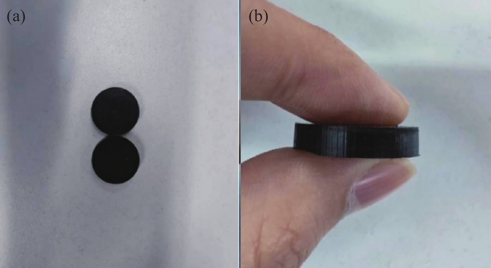
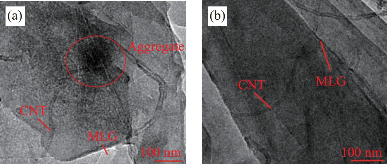
1800 r/min的转速下搅拌一定的时间。搅拌完成后按混合比例1.5wt%加入硅胶固化剂(深圳红叶科技,主要成分为聚硅氧烷)再次搅拌1~2 min,并将搅拌混合后的聚合材料注入模具并放置于RS-1型真空箱(河南沃林仪器设备有限公司)中进行排气处理15 min,然后将模具放入设定的高温干燥箱中加热3 h,最后取出放置于室温下待自然冷却成形。图2为厚度4 mm、直径20 mm的圆形片状体,图3为触觉敏感单元在透射电镜(FEI Tecnai F20,日本电子) 100 nm放大倍数下改性前后的微观结构,从图3(a)可以明显看出,改性前CNT/MLG团聚现象较明显,且分布相对随机。而在改性后,如图3(b)所示,团聚明显减少,导电颗粒联系紧密且在基体中的分布相对更加均匀,保证了其稳定的传感性能。![]() 图 3 触觉敏感单元改性前(a)和改性后(b)对比Figure 3. Comparison between before (a) and after (b) modification of the tactile sensitivity unit
图 3 触觉敏感单元改性前(a)和改性后(b)对比Figure 3. Comparison between before (a) and after (b) modification of the tactile sensitivity unit1.2 试验方法
1.2.1 灵敏度测量及模型推理
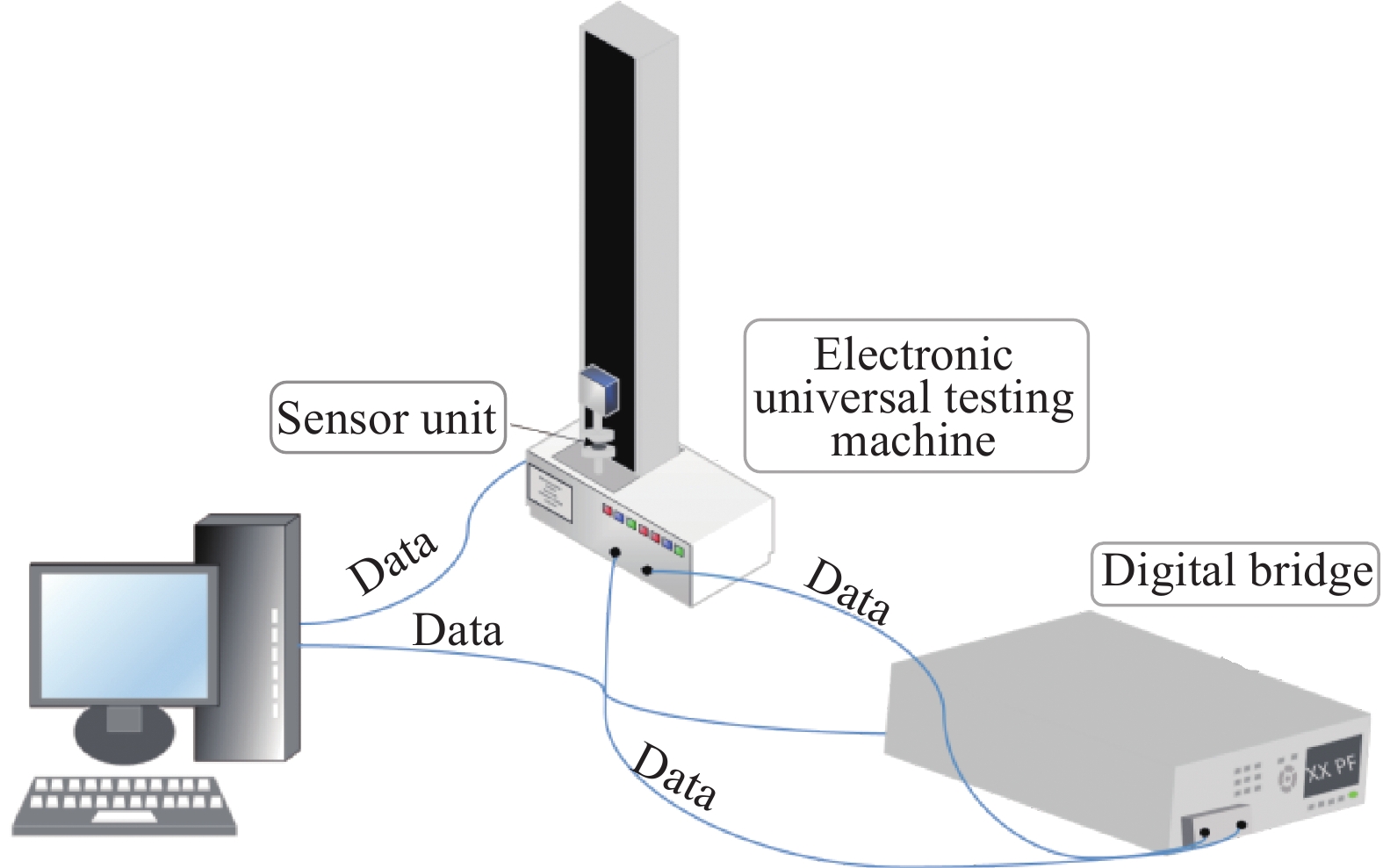
灵敏度是衡量电容式传感器性能的重要指标,它代表了压力传感器电容量与载荷的相对变化关系[29],式(1)为灵敏度的函数表达式。如图4所示,测量过程中使用微机控制电子万能试验机(FBS200N,弗布斯检测设备有限公司)与LCR数字电桥(UC2836B,优策电子科技有限公司)构成压力传感器电容测试回路,将样品放置在试验机中,使用试验机对样品施加0~30 kPa的单轴压力使样品产生塑性变形,同时通过LCR数字电桥和采集软件监测电容变化数据。最后得到不同压力情况下的压力传感器电容变化:
S=δ(ΔC/C0)δP=(εA/d−εA/d0)/(εA/d0)EΔd/d0 (1) 式中:S表示灵敏度(kPa−1);C0为不施加压力时的初始电容值(pF);ΔC=C−C0表示电容变化量,其中C为单轴压力条件下的电容值;P表示施加的压力(kPa);E为弹性模量;d0是复合材料的初始厚度,Δd=d−d0是压缩过程中的材料厚度变化;复合压敏材料介电常数为ε;电极正对面积为A。
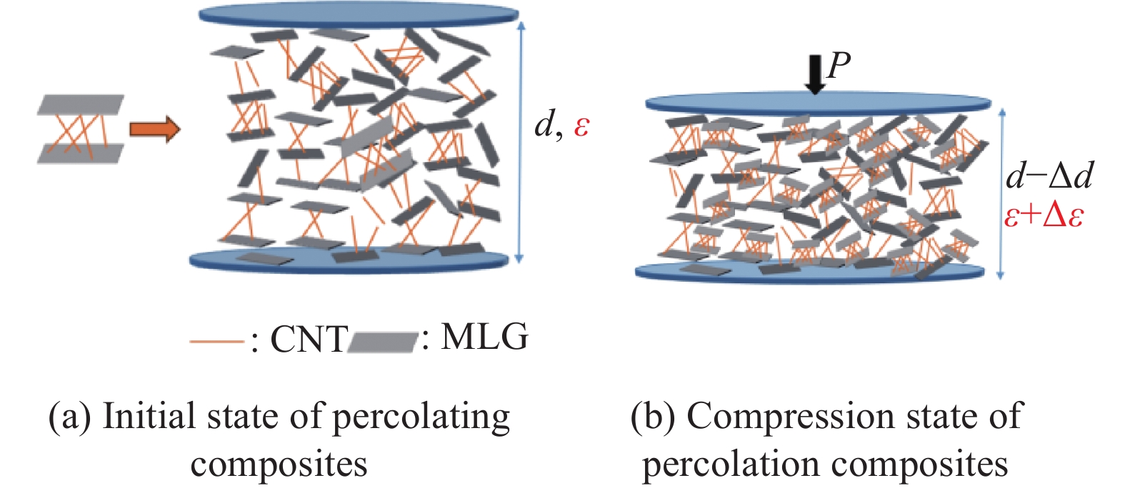
根据渗流理论[30-31],在以CNT、MLG为填料的渗滤复合材料中,介电常数不再是固定的常数。渗滤复合材料作为介电层的柔性电容式压力传感器的工作原理如图5所示,在压缩过程中,填料浓度局部增加。介电常数随着浓度的增加而增加,当浓度接近渗流阈值时,介电常数增加速率变得更快,最终形成导电通路。
![]() 图 5 渗滤复合材料作为介电层的柔性电容式压力传感器的工作原理图d—Initial thickness; ε—Initial dielectric constant; P—Applied pressure; d–Δd—Material thickness after compression; ε+Δε—Dielectric constant of the composite pressure-sensitive material after compressionFigure 5. Working principle diagram of flexible capacitive pressure sensor with percolation composite as dielectric layer
图 5 渗滤复合材料作为介电层的柔性电容式压力传感器的工作原理图d—Initial thickness; ε—Initial dielectric constant; P—Applied pressure; d–Δd—Material thickness after compression; ε+Δε—Dielectric constant of the composite pressure-sensitive material after compressionFigure 5. Working principle diagram of flexible capacitive pressure sensor with percolation composite as dielectric layer基于如下幂律方程所示:
ε=εd(fC−f)−t/(f<fC) (2) 其中:f和fC分别是导电填料的浓度和渗流阈值;ε和εd分别为复合材料和基体的介电常数;t表示比例常数。
故传感器的电容变化率可表示为下式,其中压敏单元厚度压缩比λ=d/d0:
ΔCC0=(εA/d−εA/d0)εA/d0=ελε0−1=[(fC−f0)/(fC−f)]tλ−1 (3) 综合上述表达式得到最终的传感器灵敏度解析模型如下:
S=[(fC−f0)/(fC−f)]t/λ−1E(λ−1) (4) 式中,f0表示初始状态的导电填料浓度。
由式(4)可知,电容式压力触觉敏感单元的灵敏度与聚合物纳米复合材料的介电性能和弹性模量密切相关。而合适的填料含量及填料在基体中的分布是否均匀是保证传感器优异介电性能的重要因素,同时根据Yang等[32]的研究可知,弹性模量E的屈服强度与温度密切相关。故本文将以填料含量、搅拌时间、成型温度作为主要影响因素,对触觉单元的灵敏度性能进行优化。
1.2.2 单因素实验设计
单因素实验设计是分别研究不同填料配比、搅拌时间、成型温度对传感器灵敏度性能的影响,为后续多因素实验设计提供一个合理的数值范围,如表1所示。试验时,首先固定MLG的含量为0.6 g,搅拌时间15 min,成型温度为 80℃,改变CNT的含量,分别是0.4、0.5、0.6、0.7、0.8、0.9、1.0、1.1 g;同理,固定 CNT的含量为0.7 g,保持搅拌时间与成型温度不变,改变MLG的含量,分别是0.4、0.5、0.6、0.7、0.8、0.9、1.0、1.1 g;而后保持CNT、MLG的含量与成型温度不变,分别为0.7 g、0.6 g、80℃,改变压力传感器制备过程中的搅拌时间分别为10、15、20、25、30 min;最后在保持填料含量与搅拌时间不变的情况下改变固化温度分别为40、60、80、100、120℃。实验重复 3 次,每个指标在相同条件下测定 3 次,最终得到同一条件下制备的传感器的平均灵敏度。
表 1 单因素实验方案Table 1. Single-factor protocolIndex Content of CNT/g Content of MLG/g Mixing time/min Molding temperature/℃ 1 0.4, 0.5, 0.6, 0.7, 0.8, 0.9,
1.0, 1.10.6 15 80 2 0.7 0.4, 0.5, 0.6, 0.7, 0.8, 0.9,
1.0, 1.115 80 3 0.7 0.6 10, 15, 20, 25, 30 80 4 0.7 0.6 15 40, 60, 80, 100, 120 1.3 预测与优化方法
1.3.1 响应面法(RSM)
响应面法(RSM)是一种用以评估一个或多个输出和输入参数之间关系建模方法,其计算量低,采用随机无偏设计,可以减少许多不必要的实验消耗,节约实验的时间与经济成本[33]。RSM中输入参数与输出变量之间的函数关系如下:
y=α0+N∑i=1αixi+N∑i=1αiix2i+∑i<j∑αijxixj (5) 其中:y是响应变量;xi是输入参数;α0表示偏差;αi表示线性效应;αii表示因素的平方效应;αij表示影响因素之间的交互效应。
RSM的实验设计法(DEO)主要分为两类:中心复合设计法(CCD)和Box-Behnken设计法(BBD)。为尽可能多的获取最佳实验条件,本文采用CCD法,进行多因素实验设计,其中每个输入参数有5个编码水平,分别为−2、−1、0、+1、+2。
图6(a)~6(d)分别为在得到每个单因素的实验结果后,根据其实验结果,以影响效果最大的点为中心点,确定了每个影响因素的实验范围,然后在实验范围内应用RSM确定多因素的实验方案,每个输入的具体水平因子显示在表2中,具体的CCD多因素实验方案如表3所示。
![]() 图 6 输入参数的单因素影响:(a) CNT含量;(b) MLG含量;(c) 搅拌时间;(d) 成型温度Figure 6. Single factor effect of input parameter: (a) CNT content; (b) MLG content; (c) Mixing time; (d) Molding temperature表 2 4个因素的水平和编码Table 2. Level and code of four factors
图 6 输入参数的单因素影响:(a) CNT含量;(b) MLG含量;(c) 搅拌时间;(d) 成型温度Figure 6. Single factor effect of input parameter: (a) CNT content; (b) MLG content; (c) Mixing time; (d) Molding temperature表 2 4个因素的水平和编码Table 2. Level and code of four factorsCode Levels factor CNT/g MLG/g Mixing
time/minMolding
temperature/℃−2 0.7 0.6 10 40 −1 0.8 0.7 15 60 0 0.9 0.8 20 80 1 1.0 0.9 25 100 2 1.1 1.0 30 120 表 3 多因素中心组合实验设计(CCD)与结果Table 3. Multifactorial central combinatorial experimental design (CCD) and resultsRun Factor Sensitivity/
(kPa−1)CNT MLG Mixing
timeMolding
temperature1 1 −1 −1 1 0.227 2 0 0 2 0 0.130 3* 0 0 0 0 0.118 4 −1 −1 −1 1 0.058 5 1 1 1 1 0.191 6 1 −1 −1 −1 0.208 7 −1 1 1 1 0.025 8* 0 0 0 0 0.145 9 −1 1 −1 1 0.050 10 −1 −1 1 −1 0.125 11 −2 0 0 0 0.050 12 0 −2 0 0 0.185 13 0 0 −2 0 0.193 14 −1 1 1 −1 0.164 15 1 1 −1 −1 0.375 16 1 −1 1 −1 0.180 17* 0 0 0 0 0.135 18 1 1 1 −1 0.310 19 0 1 0 0 0.198 20 2 0 0 0 0.478 21 −1 1 −1 −1 0.178 22 0 0 0 0 0.154 23 1 1 −1 1 0.326 24 0 0 0 −2 0.124 25* 0 0 0 0 0.117 26* 0 0 0 0 0.112 27 −1 −1 −1 −1 0.078 28 1 −1 1 1 0.248 29 −1 −1 1 1 0.090 30 0 0 0 2 0.073 Note: * indicates the central repeated trials. 1.3.2 支持向量回归(SVR)
支持向量机(SVM)是一种机器学习方法,如图7所示,它通过在高维空间中构建一个或一组超平面来实现分类或回归,其中用于回归的方法称为支持向量回归(SVR)。在SVR模型中核函数用以解决线性不可分的问题,其基本的数学表达式如下:
![]() 图 7 支持向量机回归(SVR)模型示意图Figure 7. Support vector machine regression (SVR) model diagramxn represents the independent variable; wij represents the weight coefficient; (βi, βi*) represents the Lagrange multiplier used for dual space transformation; K(x, xi) represents the kernel function used to solve the quadratic equation; b represents the deviation; y represents the dependent variable
图 7 支持向量机回归(SVR)模型示意图Figure 7. Support vector machine regression (SVR) model diagramxn represents the independent variable; wij represents the weight coefficient; (βi, βi*) represents the Lagrange multiplier used for dual space transformation; K(x, xi) represents the kernel function used to solve the quadratic equation; b represents the deviation; y represents the dependent variabley=n∑i=1(βi−β∗i)K(x,xi)+b (6) 其中:(βi, β∗i)表示用于对偶空间变换的拉格朗日乘数;K(x,xi)表示用于求解二次方程的核函数;b表示偏差。
由于核函数是影响SVR模型精度的重要因素之一,因此为SVR模型选择合适的核函数尤为重要。目前,支持向量回归模型的核函数主要分为4种类型,即线性、多项式、径向基函数(RBF)和sigmoid。此外,核函数选取后,算法的超参数如g、C和ε也会影响SVR模型的性能,因此超参数的选取也是SVR建模的关键步骤。在本文中,RBF被用作模型计算的核函数,超参数优化则采用K折交叉验证的网格搜索方法(图8)。
1.3.3 蜣螂优化算法及其改进(IDBO)
蜣螂优化算法(DBO)作为一种新型启发式群智能优化算法,通过模拟蜣螂的滚球、跳舞、觅食、偷窃和繁殖等行为实现种群全局范围内最优值的选择。其适应度值作为衡量优化结果优劣的标准,优化的具体流程如图9所示。
![]() 图 9 蜣螂优化算法(DBO)流程图Figure 9. Dung beetle optimization (DBO) algorithm flowchartt—Number of iterations at the present stage; T—Number of iterations set by the algorithm
图 9 蜣螂优化算法(DBO)流程图Figure 9. Dung beetle optimization (DBO) algorithm flowchartt—Number of iterations at the present stage; T—Number of iterations set by the algorithm同其他群智能优化算法类似,DBO通过随机生成位置的方式实现种群的初始化,但这容易出现种群分布不均匀,导致种群多样性减少,种群质量不高,从而影响算法的收敛速度及搜索性能。为了能够让个体在算法开始时有较高的全局搜索能力,需要让种群的位置均匀分布在整个问题的解空间内,混沌作为一种非线性的自然现象,因其混沌序列具有遍历性、随机性等优点,被广泛用于优化搜索问题。利用混沌变量搜索显然比无序随机搜索具有更大的优越性,因此本文采用改进的Tent混沌映射[34]替换原算法的初始化。原算法初始化与改进的Tent混沌初始化表达式如下:
xi,j=lbj+ri,j(ubj−lbj) (7) 式中:ri,j表示随机数列;lbj、ubj分别表示算法种群维度的上下界。
{2xi+rand(0,1)1N, 0⩽ (8) 式中, N 是序列内粒子的个数。引入随机变量 \mathrm{r}\mathrm{a}\mathrm{n}\mathrm{d}\left(0,1\right)/N 不仅仍然保持了Tent混沌映射的随机性、遍历性、规律性,而且能够有效避免迭代落入小周期点和不稳定周期点内。
在对种群初始化进行优化后,为了提升算法在迭代的不同时期全局/局部搜索能力。本文参考了文献[35]采用自适应 t 分布扰动策略,使DBO算法获得更优异的搜索性能。改进后的全局搜索位置更新公式为
\left\{\begin{array}{l}\mathrm{if\ rand} < p \\ x_i^t=x_i+x_it\left(i_{\mathrm{t}\mathrm{e}\mathrm{r}}\right)\end{array}\right. (9) 式中: p=0.5-0.1\left(T-t\right)/T 表示扰动概率; {x}_{{{i}}}^{t} 为突变后的蜣螂位置; {x}_{{{i}}} 为第 i 只蜣螂个体位置; t\left({i}_{\mathrm{t}\mathrm{e}\mathrm{r}}\right) 是以迭代次数 {i}_{\mathrm{t}\mathrm{e}\mathrm{r}} 为自由度的 t 分布函数;T为算法设定的迭代次数。
通过自适应 t 分布突变扰动策略虽然能增强算法全局搜索和跳出局部最优的能力,但是无法确定扰动之后得到的新位置一定比原位置的适应度值要好,因此在进行变异扰动更新后,加入贪婪策略[36],通过比较新旧两个位置的适应度值,确定是否要更新位置。贪婪策略表达式如下:
{x}_{{{i}}}^{\mathrm{n}\mathrm{e}\mathrm{w}}\left(t\right)=\left\{\begin{array}{l}{x}_{{{i}}}^{}\left(t\right),\left(f\right({x}_{{{i}}}^{}\left(t\right)) < f({x}_{{\mathrm{g}}}\left(t\right)))\\ {x}_{{\mathrm{g}}}\left(t\right),\left(f\right({x}_{{{i}}}^{}\left(t\right)) > f({x}_{{\mathrm{g}}}\left(t\right)))\end{array}\right. (10) 其中: {x}_{{{i}}}^{\mathrm{n}\mathrm{e}\mathrm{w}}\left(t\right) 为经过贪婪规则更新后的个体位置; {x}_{{{i}}}\left(t\right) 为扰动后的个体; {x}_{{\mathrm{g}}}\left(t\right) 为扰动前的个体; f 代表蜣螂适应度函数。
IDBO算法的具体流程如图10所示。
![]() 图 10 改进蜣螂优化算法(IDBO)流程图P— Disturbance probabilityFigure 10. Improved dung beetle optimization (IDBO) algorithm flowchart
图 10 改进蜣螂优化算法(IDBO)流程图P— Disturbance probabilityFigure 10. Improved dung beetle optimization (IDBO) algorithm flowchart为了验证所提蜣螂优化算法改进策略的有效性,本文将改进的IDBO与4种被广泛研究的优化算法(粒子群算法(PSO)、遗传算法(GA)、灰狼优化算法(GWO)、DBO)进行了比较。选取多种标准测试函数[37]评价其性能表现。其中,F1~F3为高维单峰测试函数,F4~F6为高维多峰测试函数。为保证实验公平性,所有算法的迭代次数与种群数都设置为100,结果如图11所示。
![]() 图 11 算法性能对比收敛曲线图GA—Genetic algorithm; PSO—Particle swarm optimization; GWO—Grey wolf optimizerFigure 11. Algorithm performance comparison convergence plot
图 11 算法性能对比收敛曲线图GA—Genetic algorithm; PSO—Particle swarm optimization; GWO—Grey wolf optimizerFigure 11. Algorithm performance comparison convergence plot由图11可以看出,改进后的蜣螂算法在搜索精度及收敛速度上皆优于其他算法,其性能得到了显著提高。
1.3.4 预测模型精度的评价指标
在本文中,由于RSM、SVR对于传感单元灵敏度的性能预测本质上是一种回归问题,因此采用决定系数(R2)、均方根误差(Rmse)和平均绝对误差(Mae)用于评估二者所建立的预测模型的准确性,具体表达式如下:
{R}^{2}=1-\frac{\displaystyle\sum _{i=1}^{n}{\left({Y}_{{{i}}}-{{Y}_{\mathrm{p}\mathrm{r}\mathrm{e}\mathrm{d}}}_{{{i}}}\right)}^{2}}{\displaystyle\sum _{i=1}^{n}{\left({Y}_{{{i}}}-\overline{Y}\right)}^{2}} (11) {R}_{\mathrm{m}\mathrm{s}\mathrm{e}}=\sqrt{\frac{1}{N}\sum _{i=1}^{N}{\left({Y}_{{{i}}}-{{Y}_{\mathrm{p}\mathrm{r}\mathrm{e}\mathrm{d}}}_{{{i}}}\right)}^{2}} (12) {M}_{\mathrm{a}\mathrm{e}}=\frac{1}{N}\sum _{i=1}^{N}\left|{Y}_{{{i}}}-{{Y}_{\mathrm{p}\mathrm{r}\mathrm{e}\mathrm{d}}}_{{{i}}}\right| (13) 其中: {Y}_{{{i}}} 和 {{Y}_{\mathrm{p}\mathrm{r}\mathrm{e}\mathrm{d}}}_{{{i}}} 分别是通过实验测量的实际灵敏度和通过应用估算模型估算的灵敏度; \overline{Y} 是通过实验所测得灵敏度的平均值;N为本次实验测量的灵敏度样品的总个数。
2. 结果与讨论
2.1 响应面(RSM)模型的建立与分析
本实验采用Design-Expert软件对数据进行处理和分析,并通过方差分析(ANOVA)以检查RSM模型对数据的拟合情况,从而确定自变量对灵敏度的影响程度。表4为灵敏度方差分析结果。可以看出,该回归模型的F-value为32.91,P-value小于
0.0001 ,而失拟项的P-value为0.1422, 大于0.05,表明整体回归模型高度显著。RSM模型的R2为0.9685 ,证明了该模型的拟合程度较高。该回归模型的方差系数(CV)为14.86%,低于15%,CV值较低,表明其置信度较高,模型能很好地反映真实的实验数据。基于F-value的显著性排序为CNT>MLG>成型温度>搅拌时间。根据CCD的ANOVA回归系数,灵敏度与填料配比、搅拌时间、成型温度的响应关系可表示为表 4 灵敏度响应的方差分析Table 4. Analysis of variance for sensitivity responseSource Sum of squares df Mean square F-value P-value Status Model 0.2877 14 0.0205 32.91 < 0.0001 Significant {x}_{1} -CNT 0.1931 1 0.1931 309.36 < 0.0001 {x}_{2} -MLG 0.0117 1 0.0117 18.789 0.0006 {x}_{3} -Mixing time 0.0036 1 0.0036 5.73 0.0302 {x}_{4} -Temperature 0.0106 1 0.0106 17.02 0.0009 {x}_{1}{x}_{2} 0.0047 1 0.0047 7.46 0.0155 {x}_{1}{x}_{3} 0.0038 1 0.0038 6.11 0.0259 {x}_{1}{x}_{4} 0.0036 1 0.0036 5.81 0.0292 {x}_{2}{x}_{3} 0.0060 1 0.0060 9.68 0.0071 {x}_{2}{x}_{4} 0.0136 1 0.0136 21.83 0.0003 {x}_{3}{x}_{4} 0.0001 1 0.0001 0.2211 0.6449 {{x}_{1}}^{2} 0.0267 1 0.0267 42.79 < 0.0001 {{x}_{2}}^{2} 0.0085 1 0.0085 13.65 0.0022 {{x}_{3}}^{2} 0.0008 1 0.0008 1.26 0.2795 {{x}_{4}}^{2} 0.0030 1 0.0030 4.88 0.0432 Residual 0.0094 15 0.0006 Lack of fit 0.0079 10 0.0008 2.70 0.1422 Not significant Pure error 0.0015 5 0.0003 Cor total 0.2970 29 {R}^{2} 0.9685 {R}_{\mathrm{A}\mathrm{d}\mathrm{j}}^{2} 0.9390 {R}_{\mathrm{P}\mathrm{r}\mathrm{e}\mathrm{d}}^{2} 0.8311 CV/% 14.86 Adequate precision 23.8126 Notes: Cor total—Total number of correlation coefficients; {R}_{\mathrm{A}\mathrm{d}\mathrm{j}}^{2} —Adjusted coefficient of determination; {R}_{\mathrm{P}\mathrm{r}\mathrm{e}\mathrm{d}}^{2} —Predicted coefficient of determination; Adequate precision is an important statistical metric for evaluating the predictive ability of response surface models; CV—Coefficient of variance; df—Number of independent variables. \begin{split} Y=&0.1324+0.0897{x}_{1}+0.0250{x}_{2}-0.0122{x}_{3}-\\ &0.0210{x}_{4}+0.0171{x}_{1}{x}_{2}-0.0154{x}_{1}{x}_{3}+0.0151{x}_{1}{x}_{4}- \\ &0.0194{x}_{2}{x}_{3}-0.0292{x}_{2}{x}_{4}-0.0029{x}_{3}{x}_{4}+0.0309{{x}_{1}}^{2}+\\ &0.0228{{x}_{2}}^{2}+0.0053{{x}_{3}}^{2}-0.0104{{x}_{4}}^{2}\\[-1pt]\end{split} (14) 式中: Y 表示响应值,代表预测灵敏度; {x}_{1} 、 {x}_{2} 分别表示CNT和MLG的含量; {x}_{3} 代表搅拌时间; {x}_{4} 表示成型温度。
图12展示了各因素之间交互作用对灵敏度的影响,当研究两个因素之间交互时,其余两个因素处于中心水平状态。
![]() 图 12 灵敏度三维响应面图:(a) CNT/MLG相互作用;(b) CNT/搅拌时间相互作用;(c) CNT/成型温度相互作用;(d) MLG/搅拌时间相互作用;(e) MLG/成型温度相互作用;(f)搅拌/成型温度相互作用Figure 12. Three-dimensional response surface plots of sensitivity: (a) Interaction between CNT/MLG content; (b) Interaction between CNT/mixing time; (c) Interaction between CNT/molding temperature; (d) Interaction between MLG/mixing time; (e) Interaction between MLG/molding temperature; (f) Interaction between mixing time/molding temperature
图 12 灵敏度三维响应面图:(a) CNT/MLG相互作用;(b) CNT/搅拌时间相互作用;(c) CNT/成型温度相互作用;(d) MLG/搅拌时间相互作用;(e) MLG/成型温度相互作用;(f)搅拌/成型温度相互作用Figure 12. Three-dimensional response surface plots of sensitivity: (a) Interaction between CNT/MLG content; (b) Interaction between CNT/mixing time; (c) Interaction between CNT/molding temperature; (d) Interaction between MLG/mixing time; (e) Interaction between MLG/molding temperature; (f) Interaction between mixing time/molding temperature由图12(a)可以看出,随着CNT和MLG含量的提升,灵敏度的提升十分显著,这是由于这类碳基材料具有优异的导电性和柔顺性,两者结合能够实现基于二维石墨烯蜂窝结构与一维碳纳米管的三维导电网络,从而进一步增强其分散性[38],增加填料与基体间的接触面积[39],从而提升传感器的介电性能,这也与式(4)的推论相互印证。根据图12(b)、图12(d)可知,在CNT或MLG含量一定时,传感器的灵敏度性能随着搅拌时间的增加改变并不明显,而随着搅拌时间的继续增加,灵敏度有下降的趋势。这是由于长时间的混合剪切破坏了填料内部的三维导电网络结构[40],这也表明适合的搅拌时间对压力传感器灵敏度的重要性。从图12(c)、图12(e)可知,在固化过程中随着温度的升高灵敏度逐渐下降。这是由于在高温固化的过程中基体持续软化使CNT和MLG之间的平均间距减小,这样便容易发生导电颗粒的团聚现象,从而对压力传感器的力学性能、电学性能产生了负面影响[41]。而从图12(f)可以了解到,在没有导电填料的情况下,仅对硅橡胶(RTV)基体进行搅拌和高温固化并不会对传感器的性能造成实质性的影响。
2.2 支持向量机回归(SVR)模型的建立与优化
基于上述CCD的数据样本,以CNT含量、MLG含量、搅拌时间和成型温度为输入参数,灵敏度为预测的输出变量建立预测模型。如图13所示,利用网格搜索法优化SVR的超参数,当C为
68.5935 ,g为0.7071 时,在5折交叉验证下的均方误差(MSE)达到最小值,平均R2值最大,即模型基于数据样本的预测性能达到最优。其中,基于SVR灵敏度预测模型的R2、Rmse和Mae值如表5所示。表 5 SVR模型的5折交叉验证预测性能评价指标Table 5. Performance evaluation index of SVR model by 5-fold cross-validationIndex {R}^{2} Rmse Mae 1 0.9893 0.0253 0.0193 2 0.9841 0.0328 0.0301 3 0.9735 0.0354 0.0231 4 0.9769 0.0389 0.0321 5 0.9882 0.0188 0.0151 Average 0.9824 0.0320 0.0239 Notes: Rmse—Root mean square error; Mae—Mean error rate. 从表5可以看出,在灵敏度预测性能评估中,平均R2、平均Rmse和平均Mae分别为
0.9824 、0.0320 和0.0239 ,这表明了预测值和实验值之间的高度相关性。此外,R2、Rmse和Mae的范围是0.9735 ~0.9893 、0.0188 ~0.0389 和0.0151 ~0.0321 ,这表明模型预测的波动范围极小,证明了此预测模型的高鲁棒性、高置信度。2.3 RSM与SVR预测模型对比
如表6所示,为比较两种模型的预测性能,基于式(10) RSM回归模型对相同数据进行了5折交叉验证。
表 6 响应面法(RSM)模型的5折交叉验证预测性能评价指标Table 6. Performance evaluation index of response surface methodology (RSM) model by 5-fold cross-validationIndex R2 Rmse Mae 1 0.9563 0.04002 0.03623 2 0.9642 0.02701 0.02443 3 0.9778 0.03103 0.02671 4 0.9669 0.04731 0.03113 5 0.9782 0.03312 0.02608 Average 0.96868 0.035698 0.028916 根据表5、表6的平均比较结果表明,SVR模型基于灵敏度性能的预测平均R2大于RSM模型,表明其适用性更好。SVR模型基于灵敏度预测的平均Rmse和Mae均小于RSM模型,更加表明超参优化后的SVR模型的预测精度优于RSM模型。
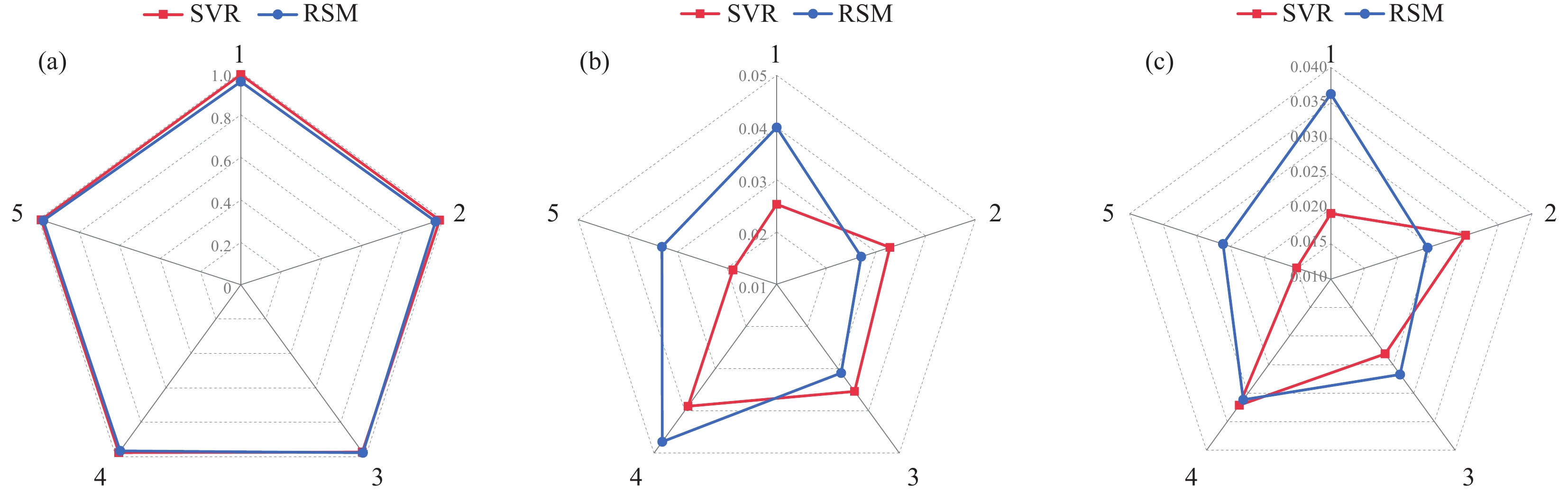
图14为SVR和RSM模型的5折交叉验证的雷达图。雷达图中可更加清楚地了解5折交叉验证下两预测模型的性能表现,图14(a)中SVR模型灵敏度的R2面积大于RSM模型,图14(b)、图14(c)中Rmse和Mae的面积均小于RSM模型,充分说明SVR模型在灵敏度的预测上具有更好的准确性。因此,通过此次比较分析表明,RSM和SVR模型在灵敏度性能预测方面都表现出良好的适应性和鲁棒性,而相较于RSM模型,SVR模型具有更好的预测效果。
![]() 图 14 SVR和RSM模型的5折交叉验证的雷达图Figure 14. Radar diagrams of SVR and RSM models with 5 fold cross validation
图 14 SVR和RSM模型的5折交叉验证的雷达图Figure 14. Radar diagrams of SVR and RSM models with 5 fold cross validation2.4 基于改进蜣螂算法(IDBO)的模型优化
此优化过程是为了获得与灵敏度相适应的最佳材料配比及制作成型的工艺参数。通过上述的研究分析可知,由于通过超参优化后的SVR模型预测性能相优于RSM模型,故选择SVR模型用作优化的目标函数模型。通过IDBO算法不断迭代寻找最优的工艺参数,其中种群数量设为50,变量维度为4,迭代次数100次,迭代过程中的群体最优适应度值如图15所示。可知,随着迭代次数的增加,种群最优的适应度值也在不断上升,直至找到SVR模型的最优解,经过10次迭代后达到最佳适应度,即灵敏度性能达到最优,随后基本保持不变。最优的材料配比及制作工艺为CNT占比2.3wt%、MLG占比1.9wt%、搅拌时间15 min、成型温度78℃,仿真灵敏度为
0.5512 kPa−1。2.5 实验验证与对比
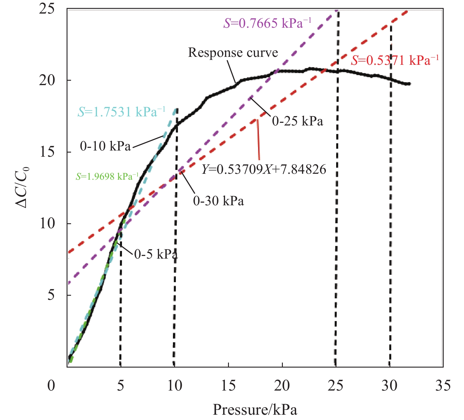
为了验证上述实验分析的合理性,根据上述优化结果的数据进行传感单元样品的制作,图16为所制作传感单元的灵敏度性能图,拟合直线斜率表示压力传感器在0~30 kPa时灵敏度大小。可知,采用优化后数据所制备的传感单元灵敏度S相较未优化时有大幅提升,达到
0.5371 kPa−1,与仿真灵敏度的相对误差为2.625%,也证明了基于SVR-IDBO优化预测模型的可靠性。![]() 图 16 灵敏度测试电容输出响应曲线S—Sensitivity; ΔC/C0—Relative change of the capacitanceFigure 16. Sensitivity test capacitor output response curves
图 16 灵敏度测试电容输出响应曲线S—Sensitivity; ΔC/C0—Relative change of the capacitanceFigure 16. Sensitivity test capacitor output response curves表7为本文所制备的柔性电容传感单元与近年来相关柔性压力传感器的灵敏度性能比较情况[12, 42-45]。结果表明,在相同压力载荷下,本文的传感器单元灵敏度性能处于较高的水平。其中,在同等压力下与张鹏等[45]的研究相比,灵敏度性能提升了5倍,与Yan等[44]相比提升了1.4倍,与药芳萍等[12]、赵珂[42]相比较,灵敏度性能分别提升了1.7倍与2.5倍。且与原始实验相比灵敏度最高提升了20倍。进一步表明结合SVR-IDBO方法进行触觉敏感单元性能优化的有效性与优越性。
表 7 传感单元灵敏度性能对比Table 7. Comparison of sensitivity performance of sensing unitsMethod Sensitivity/ \mathrm{kP}\mathrm{a}^{-1} Pressure range/ \mathrm{k}\mathrm{P}\mathrm{a} Comparison/ \mathrm{kP}\mathrm{a}^{-1} Ref. Microstructure design 0.451 0-25 0.7665 [12] Microstructure design 0.69 0-10 1.7531 [42] Microstructure design 1.01 0-25 0.7665 [43] Mechanical blending 0.3850 0-30 0.5371 [44] Microstructure design 0.341 0-5 1.9698 [45] Mechanical blending 0.5371 0-30 – This study 3. 相关性能测试
为满足传感器在实际场景的应用,本文的柔性触觉敏感单元除了在宽传感范围内具备较高的灵敏度之外,还具备其他较理想的特性,包括快速响应、高重复稳定性、良好的耐用性等。
如图17(a)所示,使用万能试验机对触觉敏感单元进行加载和卸载,在10 mm/min的较慢载荷进行速度下,其响应时间和恢复时间均能达到1 s,且每一循环峰值都极为接近,表明其在快速响应的同时也保证了电容信号的稳定传输。
如图17(b)、图17(c)所示,在15 kPa、30 kPa、45 kPa的载荷范围内进行10次循环测试,均能表现出良好的电容输出稳定性。且通过施加0~30 kPa的300次循环载荷也体现出触觉单元在受到载荷的中后期具有良好的重复稳定性。
4. 结 论
采用机器学习与智能优化算法相结合的方式改善了基于机械共混的柔性压力传感单元的制备条件。主要工作如下:
(1)通过推导压容式传感器灵敏度的机制,确定了影响其性能的主要因素有碳纳米管(CNT)含量、石墨烯(MLG)含量、搅拌时间和成型温度。采用中心复合实验设计法(CCD)动态检测了各种因素对输出性能的影响,结果表明,所有的因素均对输出性能有显著影响,并得到了响应面法(RSM)回归模型;
(2)基于CCD的实验数据作为输入,利用超参优化后的支持向量机(SVR)算法对灵敏度进行预测建模,并与RSM预测模型进行了比较,结果表明两种方法对灵敏度性能均表现出极高的预测精度,特别是超参优化后的SVR模型的预测结果与实际结果十分接近,这也表明所提出的方法在预测多因素影响和传感器性能之间的复杂关系方面具有巨大的应用潜力;
(3)利用改进的蜣螂优化算法(IDBO)对SVR模型进行迭代优化,逆向解析出了柔性传感器单元最佳的制备条件,实验结果表明,灵敏度性能大幅提升,且与仿真结果的相对误差较低。
综上所述,本文所采用的研究方法为传感单元性能优化提供了参考,同时为智能优化算法在柔性压力传感器方面的应用提供了理论依据,并且对实现柔性传感单元的大规模、工业化生产具有一定的指导意义。
-
![]()
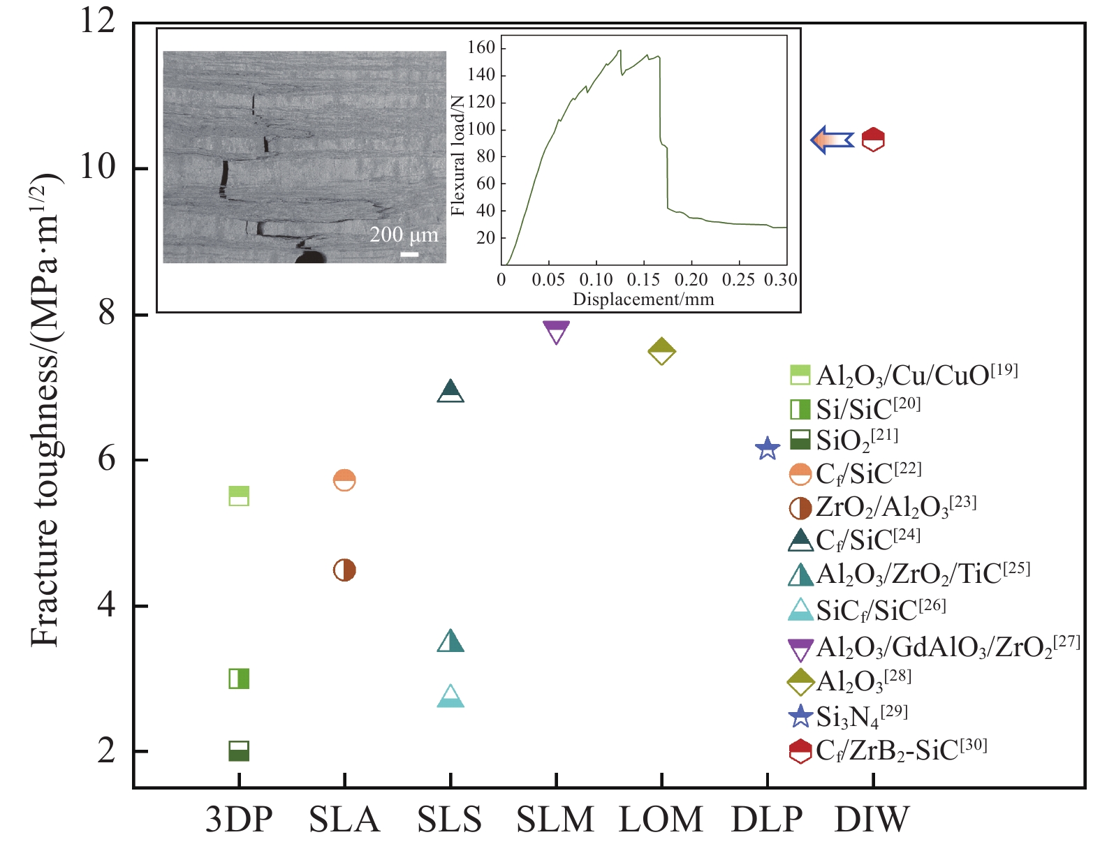
图 1 先进陶瓷及其复合材料三维打印工艺及断裂韧性[19-30]
3DP—Three dimensional printing and gluing; SLA—Stereo lithography apparatus; SLS—Selected laser sintering; SLM—Selective laser melting; LOM—Laminated object manufacturing; DLP—Digital light processing; DIW—Direct ink writing
Figure 1. 3D printing process and fracture toughness of advanced ceramics and their composite materials[19-30]
![]()
图 2 近五年公开发表的墨水直写 (DIW)工艺制造纤维强韧陶瓷基复合材料(DIW-FRCMC)的文献数量及其应用领域
Figure 2. Number of publicly published literature on direct ink writing (DIW) technologies for printing fiber reinforced ceramic matrix composites (DIW-FRCMC) in the past five years and their application area
![]()
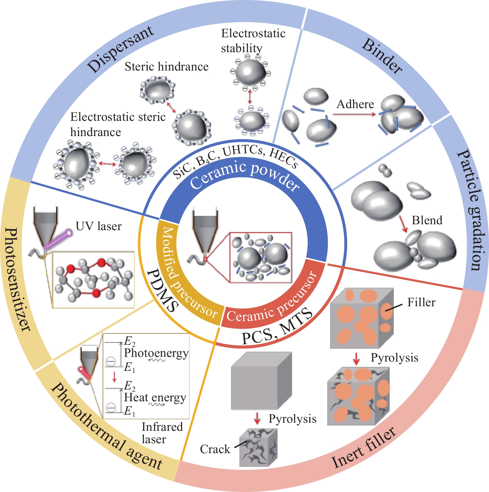
图 4 DIW工艺中陶瓷墨水组分设计及其相关作用机制
UHTCs—Ultrahigh-temperature ceramics; HECs—High entropy ceramics; PDMS—Polydimethylsiloxane; PCS—Polycarbosilane; MTS—Methyltrichlorosilane; E1—Low energy level; E2—High energy level
Figure 4. Component design and related mechanism of ceramic ink in DIW process
![]()
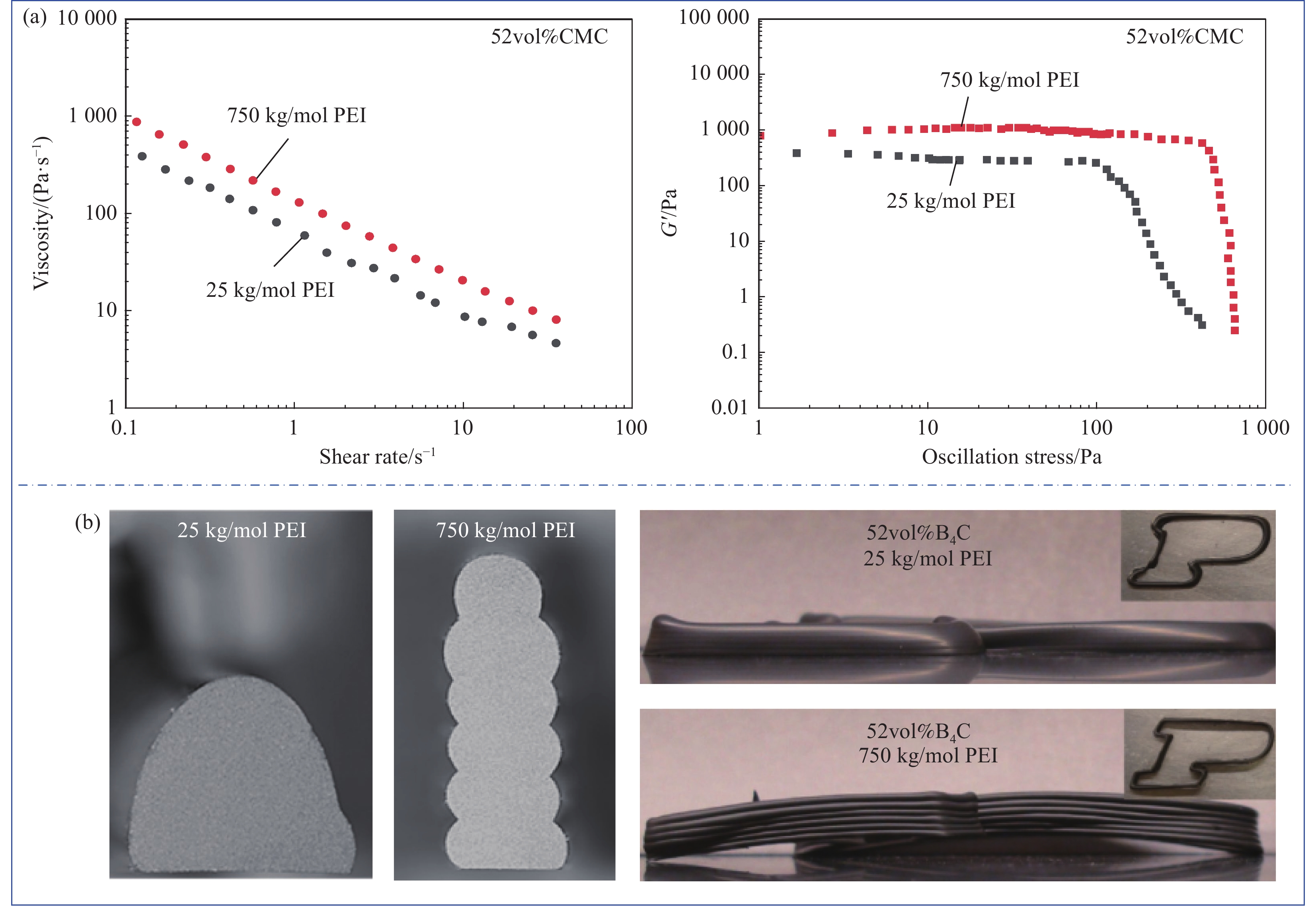
图 5 分散剂对打印性能的影响:(a) 不同聚合物分子量的流变性能;(b) 不同聚合物分子量的维型能力[45]
PEI—Polyetherimide; CMC—Carboxymethyl cellulose; G'—Storage modulus
Figure 5. Effect of dispersants on printing performance: (a) Rheological properties of different polymer molecular weights; (b) Dimensional ability of different polymer molecular weights[45]
![]()
![]()
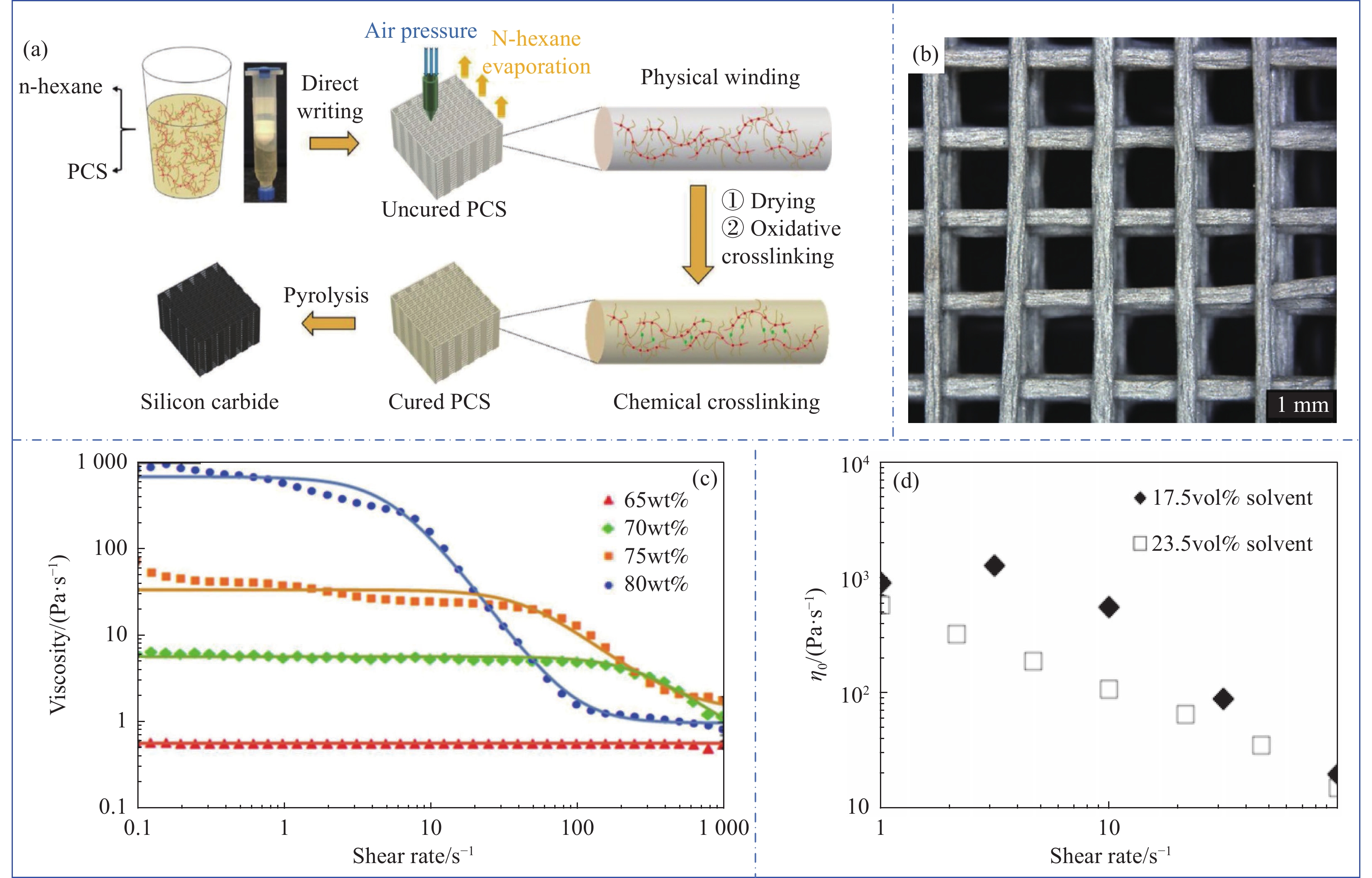
图 7 陶瓷先驱体墨水的DIW打印成型:(a) 打印工艺流程;(b) 打印结构的厚度变化;(c) 聚碳硅烷(PCS)先驱体墨水黏度和剪切速率;(d) 硼-聚碳硅烷(BPCS)先驱体墨水黏度与剪切速率[38, 51-52]
η0—Viscosity
Figure 7. DIW printing molding of ceramic precursor ink: (a) Printing process flow; (b) Thickness variation of the printing structure; (c) Viscosity and shear rate of polycarbosilane (PCS) precursor ink; (d) Viscosity and shear rate of boron polycarbosilanes (BPCS) precursor ink[38, 51-52]
![]()
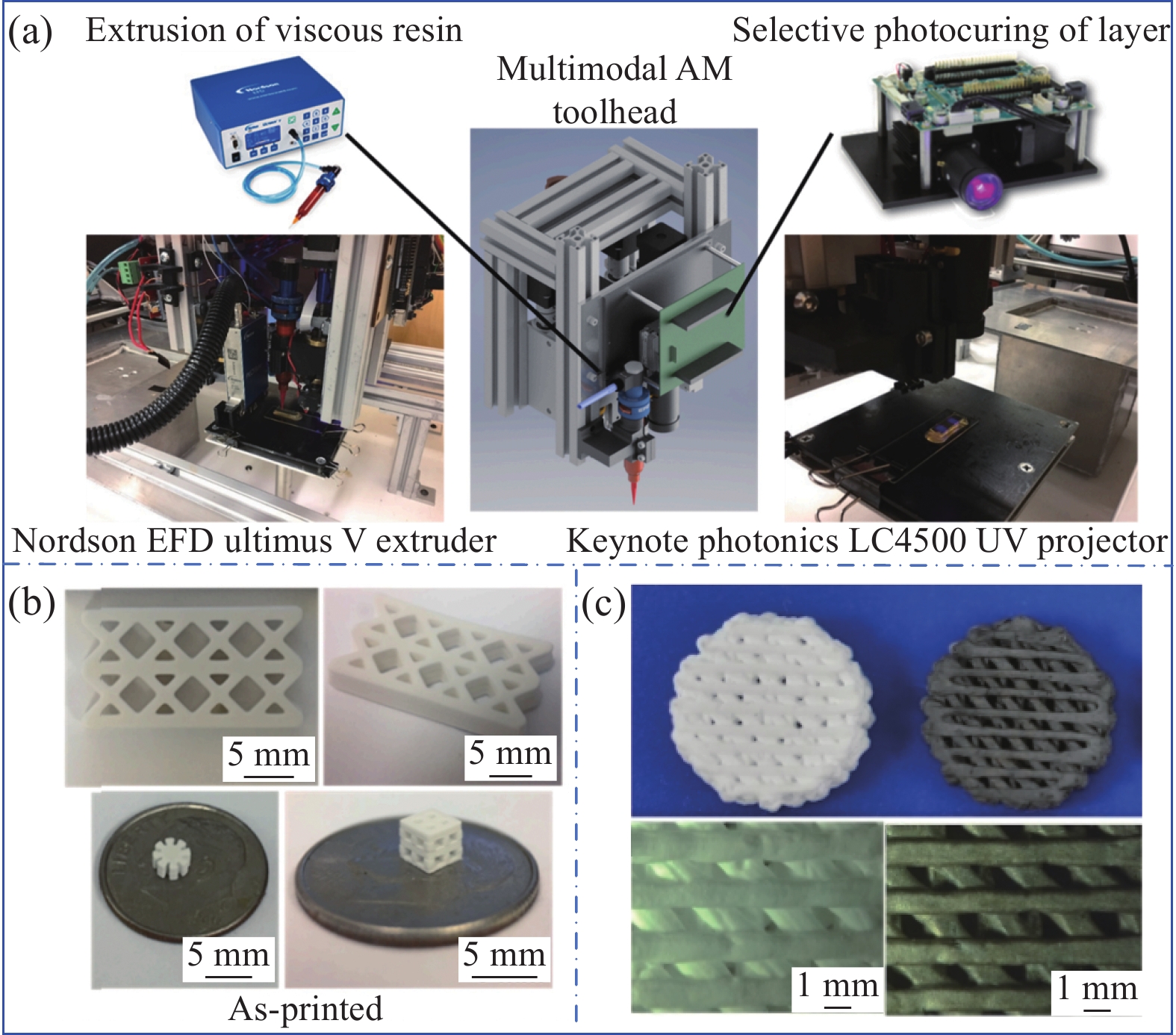
图 8 改性先驱体的DIW打印设备及工艺:(a) 紫外辅助打印设备;(b) 光敏效应墨水的打印成型;(c) 光热效应墨水的打印成型[56-57]
AM—Additive manufacturing; Nordson EFD Ultimus V—Precision dispenser for extruding photoresists
Figure 8. DIW printing equipment and process for modified precursors: (a) UV assisted printing equipment; (b) Printing and molding of photosensitive ink; (c) Printing and molding of photothermal effect ink[56-57]
![]()
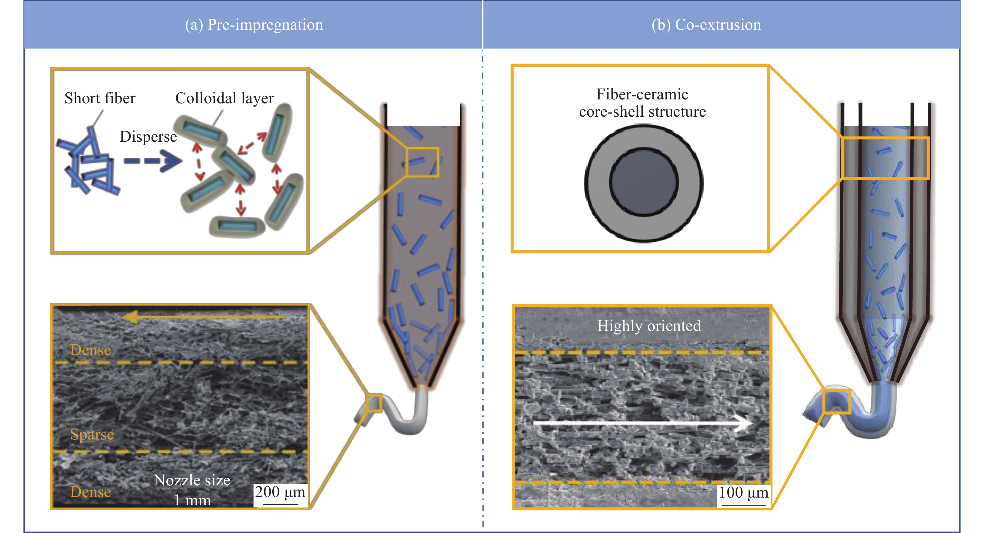
图 9 DIW工艺中短切纤维的加入方式:(a) 预先浸渍;(b) 共同挤出
Figure 9. Addition method of short cut fibers in the DIW process: (a) Pre-impregnation; (b) Co-extrusion
![]()
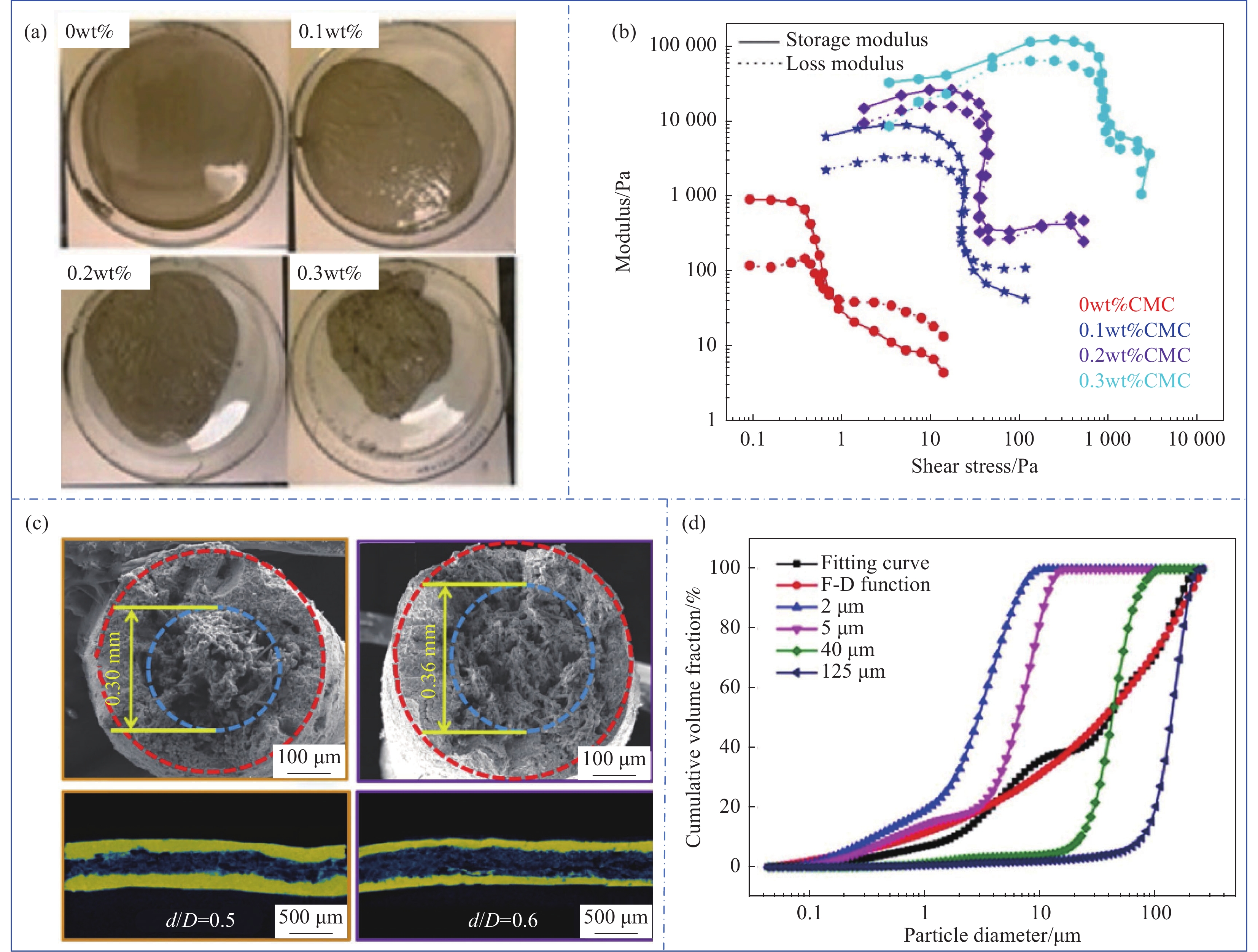
图 10 短切纤维复合材料的DIW打印成型:(a) 短切纤维体积分数和长度范围;(b) 分散剂对纤维分布影响;(c) 构件的尺寸偏差比;(d) 核壳结构复合长丝共同挤出示意图[16, 31, 42, 47, 51, 58-59]
Csf—Short carbon fiber; Cf—Carbon fiber; SiCf—Short silicon carbide fibers; AHPCS—Allylhydridopolycarbosilane; PMSSQ—Poly (methyl-silsesquioxane); MC—Methyl cellulose; L—Length; W—Width; H—Height; θ—Extrusion angle; d1—Fiber diameter at the feed rod; D1—SiC diameter at the feed rod; d2—Fiber diameter at the filament; D2—SiC diameter at the filament
Figure 10. DIW printing forming of short cut fiber composite materials: (a) Volume fraction and length range of short cut fibers; (b) Effect of dispersants on fiber distribution; (c) Dimensional deviation ratio of components; (d) Schematic diagram of co-extrusion of core-shell structure composite filament[16, 31, 42, 47, 51, 58-59]
![]()
图 11 DIW工艺中连续纤维的加入方式:(a) 连续纤维的表面上浆过程;(b) 斜插式喷嘴设计;(c) 折角式喷嘴设计;(d) 无折角喷嘴设计;(e) 超声辅助设计
Figure 11. Addition method of continuous fibers in DIW process: (a) Surface sizing process of continuous fibers; (b) Design of oblique insertion nozzle; (c) Design of angled nozzles; (d) Non angled nozzle design; (e) Ultrasound assisted design
![]()
图 12 连续纤维复合材料的DIW打印成型:(a) 多核打印系统示意图;(b) 多核墨水的流速分布;(c) 螺杆旋转输运连续纤维;(d) 超声辅助纤维分离技术[30, 46, 62]
Figure 12. DIW printing molding of continuous fiber composite: (a) Schematic diagram of multi-core printing system; (b) Flow rate distribution of multi-core ink; (c) Continuous fiber of screw rotation; (d) Ultrasonic assisted fiber separation technology[30, 46, 62]
![]()
图 13 用于DIW打印技术的后致密化工艺流程
PIP—Precursor infiltration pyrolysis process; CVI—Chemical vapor infiltration process; RMI—Reactive melt infiltration process
Figure 13. Post-compaction process flow for DIW printing technology
![]()
图 14 DIW和PIP工艺的结合:(a) 典型工艺路线;(b) PIP致密化周期;(c) PIP致密化后的微结构[64-65]
SiCw—Silicon carbide whiskers; SiCp—Silicon carbide particles; PSw—Scaffolds with the mass ratio of SiCw/PCS was 0.05:1; PSwSp—Represented for the 3D-SiC scaffolds based on pyrolyzed PCS/SiCp-based lattices; DIW—Direct ink writing; PSwTi—PSw contained Ti; PSw-1800—PSw were heated at
1800 ℃; PSw-CVI—PSw treated by chemical vapor infiltration; LPVCS—A liquid polycarbosilane; SiC3D—3D SiC-based compositesFigure 14. Combination of DIW and PIP processes: (a) Typical process route; (b) PIP densification cycle; (c) Microstructure after PIP densification[64-65]
![]()
图 15 DIW和化学气相渗透工艺(CVI)的结合:(a) 工艺流程;(b) CVI周期与拉伸强度;(c) CVI工艺制备纤维涂层;(d) 纤维表面涂层显微结构[59, 66]
Figure 15. Combination of DIW and chemical vapor infiltration (CVI) process: (a) Process flow; (b) CVI period and tensile strength;(c) Preparation of fiber coating by CVI process; (d) Microstructure of fiber surface coating[59, 66]
![]()
![]()
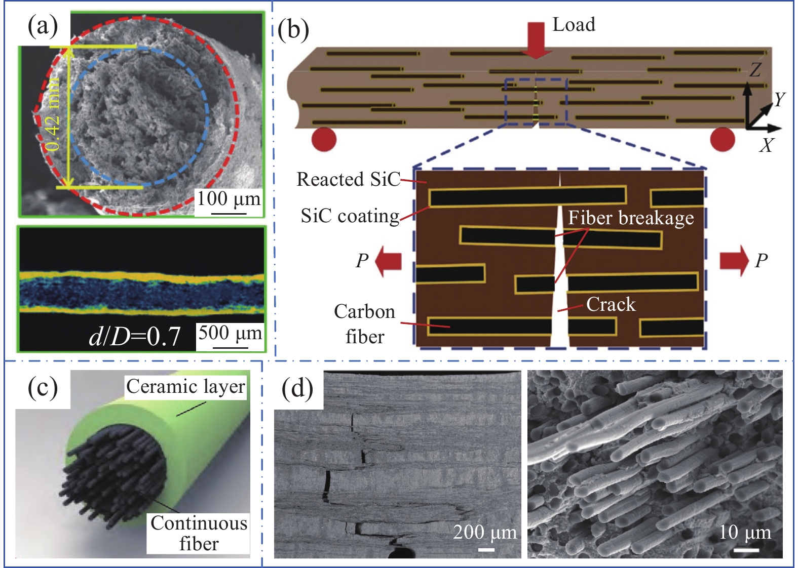
图 17 纤维强韧化机制:(a) 短切纤维核壳结构;(b) 高取向短切纤维裂纹扩展示意图;(c) 连续纤维核壳结构;(d) 连续纤维裂纹扩展示意图[30, 47, 59, 62]
P—Tension
Figure 17. Fiber strong toughness mechanism: (a) Short cut fiber core shell structure; (b) Schematic diagram of high orientation short cut fiber crack expansion; (c) Continuous fiber core shell structure; (d) Schematic diagram of continuous fiber crack expansion[30, 47, 59, 62]
表 1 DIW制造陶瓷/陶瓷复合材料研究中的构件性能
Table 1 Mechanical properties of ceramic composite materials manufacturing using the DIW technique
Ceramic phase Enhanced phase Slurry design Fiber extrusion
methodDensification
processFracture
toughness/
(MPa·m1/2)Bending
strength/MPaTensile
strength/MPaRef. SiC Ceramic powder — Sintering — 27.3 — [38] SiC Continuous carbon fiber Ceramic powder Angle deviation Sintering — 219 — [46] SiC Short carbon fiber Ceramic powder Co-extrusion
17.5vol%PIP 2.71 123 — [47] PMSSQ Short carbon fiber Ceramic precursor Pre-impregnation
33vol%Pyrolysis — — — [51] Al2O3 — Modified precursor — Sintering — 156.6 — [56] SiC Short carbon fiber Ceramic powder Pre-impregnation
17.5vol%CVI, LSI 5.82 274 — [59] SiC Short carbon fiber Ceramic powder Pre-impregnation
20vol%LSI, Carbonization — 253.63 53.68 [58] SiC Continuous carbon fiber Ceramic powder No angle deviation PIP 3.77 146 — [62] ZrB2
SiCContinuous carbon fiber Ceramic powder No angle deviation Low temperature hot pressing 10.04 388.3 — [30] SiC Continuous carbon fiber Ceramic powder Angle deviation Sintering — 232 — [61] PCS — Ceramic precursor — PIP, CVI — — 129.7 [64] PCS Short silicon carbide fiber Ceramic precursor Pre-impregnation
10vol%Pyrolysis — 102.2 — [31] ZrB2 Short carbon fiber Ceramic powder Fiber prefabricated
components
1wt%CVI, SI, RMI — — — [60] Notes: LSI—Liquid silicon infiltration process; SI—Slurry impregnation process.  下载: 导出CSV
-
[1] 张立同, 成来飞. 连续纤维增韧陶瓷基复合材料可持续发展战略探讨[J]. 复合材料学报, 2007, 24(2): 1-6. DOI: 10.3321/j.issn:1000-3851.2007.02.001 ZHANG Litong, CHENG Laifei. Discussion on strategies of sustainable development of continuous fiber reinforced ceramic matrix composites[J]. Acta Materiae Compositae Sinica, 2007, 24(2): 1-6(in Chinese). DOI: 10.3321/j.issn:1000-3851.2007.02.001
[2] KRENKEL W. Carbon fiber reinforced CMC for high-performance structures[J]. International Journal of Applied Ceramic Technology, 2004, 1(2): 188-200. DOI: 10.1111/j.1744-7402.2004.tb00169.x
[3] 汤素芳, 胡成龙, 熊艳丽, 等. 超高温陶瓷改性碳基/陶瓷基复合材料的多尺度构筑与性能研究进展[J]. 装备环境工程, 2019, 16(10): 40-48. TANG Sufang, HU Chenglong, XIONG Yanli, et al. Research progress on multi-scale structure construction and properties of ultra-high temperature ceramic modified carbon-ceramic matrix composites [J]. Equipment Environmental Engineering, 2019, 16(10): 40-48(in Chinese).
[4] 杜善义, 方岱宁, 孟松鹤, 等. “近空间飞行器的关键基础科学问题”重大研究计划结题综述[J]. 中国科学基金, 2017, 31(2): 109-114. DU Shanyi, FANG Daining, MENG Songhe, et al. Summary of major research programs of "Key Basic Science Issues of Near-space Vehicle"[J]. The China Science Foundation, 2017, 31(2): 109-114(in Chinese).
[5] 韩杰才, 洪长青, 张幸红, 等. 新型轻质热防护复合材料的研究进展[J]. 载人航天, 2015, 21(4): 315-321. DOI: 10.3969/j.issn.1674-5825.2015.04.001 HAN Jiecai, HONG Changqing, ZHANG Xinghong, et al. Research progress of novel lightweight thermal protection composites[J]. Manned Space Flight, 2015, 21(4): 315-321(in Chinese). DOI: 10.3969/j.issn.1674-5825.2015.04.001
[6] 吴甲民, 陈敬炎, 陈安南, 等. 陶瓷零件增材制造技术及在航空航天领域的潜在应用[J]. 航空制造技术, 2017, 60(10): 40-49. WU Jiamin, CHEN Jingyan, CHEN Annan, et al. Additive manufacturing of ceramic components and its potential application in aerospace field[J]. Aeronautical Manufacturing Technology, 2017, 60(10): 40-49(in Chinese).
[7] 梁栋, 何汝杰, 方岱宁. 陶瓷材料与结构增材制造技术研究现状[J]. 现代技术陶瓷, 2017, 38(4): 231-247. LIANG Dong, HE Rujie, FANG Daining. Development of additive manufacturing of ceramics[J]. Advanced Ceramics, 2017, 38(4): 231-247(in Chinese).
[8] CHEN Y L, ZHANG J M, LI Z F, et al. Manufacturing technology of lightweight fiber-reinforced composite structures in aerospace: Current situation and toward intellectualization[J]. Aerospace, 2023, 10(3): 206. DOI: 10.3390/aerospace10030206
[9] FLEISHER A, ZOLOTARYOV D, KOVALEVSKY A, et al. Reaction bonding of silicon carbides by binder jet 3D-printing, phenolic resin binder impregnation and capillary liquid silicon infiltration[J]. Ceramics International, 2019, 45(14): 18023-18029. DOI: 10.1016/j.ceramint.2019.06.021
[10] PANT M, PIDGE P, NAGDEVE L, et al. A review of additive manufacturing in aerospace application[J]. RCMA, 2021, 31(2): 109-115. DOI: 10.18280/rcma.310206
[11] Aerotech News. Air force looking to additive manufacturing to expand hypersonic flight capabilities[N]. (2019-08-06)[2024-04-19].
[12] WEST B. Additive manufacturing for affordable rocket engines[N]. (2016-01-01)[2024-4-19].
[13] MARTA I, GABRIELE N, MARINELLA L, et al. UV-assisted 3D printing of glass and carbon fiber-reinforced dual-cure polymer composites[J]. Materials, 2016, 9(7): 583-595. DOI: 10.3390/ma9070583
[14] SANG L, HAN S, PENG X, et al. Development of 3D-printed basalt fiber reinforced thermoplastic honeycombs with enhanced compressive mechanical properties[J]. Composites Part A: Applied Science and Manufacturing, 2019, 125: 105518. DOI: 10.1016/j.compositesa.2019.105518
[15] MELENKA G W, CHEUNG B K O, SCHOFIELD J S, et al. Evaluation and prediction of the tensile properties of continuous fiber-reinforced 3D printed structures[J]. Composite Structures, 2016, 153: 866-875. DOI: 10.1016/j.compstruct.2016.07.018
[16] LI S, LI Y F, WANG Q W, et al. Fabrication of 3D-SiC/aluminum alloy interpenetrating composites by DIW and pressureless infiltration[J]. Ceramics International, 2021, 47(17): 24340-24347. DOI: 10.1016/j.ceramint.2021.05.147
[17] 苑景坤, 熊书锋, 陈张伟. 聚合物前驱体转化陶瓷增材制造技术研究趋势与挑战[J]. 无机材料学报, 2023, 38(5): 477-488. DOI: 10.15541/jim20220515 YUAN Jingkun, XIONG Shufeng, CHEN Zhangwei. Research trends and challenges of additive manufacturing of polymer-derived ceramics[J]. Journal of Inorganic Materials, 2023, 38(5): 477-488(in Chinese). DOI: 10.15541/jim20220515
[18] 陈小武, 董绍明, 倪德伟, 等. 碳纤维增强超高温陶瓷基复合材料研究进展[J]. 中国材料进展, 2019, 38(9): 843-854. DOI: 10.7502/j.issn.1674-3962.201906016 CHEN Xiaowu, DONG Shaoming, NI Dewei, et al. Progress on carbon fiber reinforced ultra-high temperature ceramic matrix composites[J]. Material Progress in China, 2019, 38(9): 843-854(in Chinese). DOI: 10.7502/j.issn.1674-3962.201906016
[19] MELCHER R, MARTINS S, TRAVITZKY N, et al. Fabrication of Al2O3-based composites by indirect 3D-printing[J]. Materials Letters, 2006, 60(4): 572-575.
[20] FU Z, SCHLIER L, TRAVITZKY N, et al. Three-dimensional printing of Si/SiC lattice truss structures[J]. Materials Science and Engineering A, 2013, 560: 851-856.
[21] PAPPAS J M, DONG X. Direct 3D printing of silica doped transparent magnesium aluminate spinel ceramics[J]. Materials, 2020, 13(21): 4810.
[22] WU H D, LIU W, HE R, et al. Fabrication of dense zirconia-toughened alumina ceramics through a stereolithography-based additive manufacturing[J]. Ceramics International, 2017, 43(1): 968-972.
[23] LU Z L, LU F, CAO J W, et al. Manufacturing properties of turbine blades of carbon fiber-reinforced SiC composite based on stereolithography[J]. Materials and Manufacturing Processes, 2014, 29(2): 201-209.
[24] BAI P K, CHENG J, LIU B. Selective laser sintering of polymer-coated Al2O3/ZrO2/TiC ceramic powder[J]. Transactions of Nonferrous Metals Society of China, 2005, 15(2): 261-265.
[25] 朱伟. 非金属复合材料激光选区烧结制备与成形研究[D]. 武汉: 华中科技大学, 2018. ZHU Wei. Research on the preparation and forming of non-metallic composite materials based on selective laser sintering[D]. Wuhan: Huazhong University of Science and Technology, 2018(in Chinese).
[26] 许腾腾. 基于SLS技术的SiCf/SiC复合材料制备及其力学性能研究[D]. 哈尔滨: 哈尔滨理工大学, 2020. XU Tengteng. Preparation and mechanical properties of SiCf/SiC composites based on SLS technology[D]. Harbin: Harbin University of Science and Technology, 2020(in Chinese).
[27] LIU H F, SU H J, SHEN Z L, et al. Direct formation of Al2O3/GdAlO3/ZrO2 ternary eutectic ceramics by selective laser melting: Microstructure evolutions[J]. Journal of the European Ceramic Society, 2018, 38(15): 5144-5152.
[28] RODRIGUES S J. Solid freeform fabrication of functional silicon nitride ceramics using laminated object manufacturing[D]. Dayton: The University of Dayton, 2000.
[29] 杨玉平. ZrO2-Al2O3陶瓷的光固化制备工艺及性能表征[D]. 广州: 广东工业大学, 2019. YANG Yuping. Preparation process and performance characterization of ZrO2-Al2O3 ceramics on stereolithography[D]. Guangzhou: Guangdong University of Technology, 2019.
[30] LIU Y, CHENG Y, MA D, et al. Continuous carbon fiber reinforced ZrB2-SiC composites fabricated by direct ink writing combined with low-temperature hot-pressing[J]. Journal of the European Ceramic Society, 2022, 42(9): 3699-3707. DOI: 10.1016/j.jeurceramsoc.2022.03.045
[31] KEMP J W, DIAZ A A, MALEK E C, et al. Direct ink writing of ZrB2-SiC chopped fiber ceramic composites[J]. Additive Manufacturing, 2021, 44(10): 102049.
[32] REVELO F C, COLORADO A H. 3D printing of kaolinite clay ceramics using the direct ink writing (DIW) technique[J]. Ceramics International, 2018, 44(5): 5673-5682. DOI: 10.1016/j.ceramint.2017.12.219
[33] LU Z L, MIAO K, ZHU W, et al. Fractions design of irregular particles in suspensions for the fabrication of multiscale ceramic components by gelcasting[J]. Journal of the European Ceramic Society, 2018, 38(2): 671-678. DOI: 10.1016/j.jeurceramsoc.2017.08.002
[34] LEWICKI J P, RODRIGUEZ J N, ZHU C, et al. 3D-printing of meso-structurally ordered carbon fiber/polymer composites with unprecedented orthotropic physical properties[J]. Scientific Reports, 2017, 7(14): 43401.
[35] 姜一帆, 赵凤起, 李辉, 等. 墨水直写增材制造技术及其在含能材料领域的研究进展[J]. 火炸药学报, 2022, 45(1): 1-19. JIANG Yifan, ZHAO Fengqi, LI Hui, et al. Direct ink writing technology for additive manufacturing and its research progress in energetic materials[J]. Chinese Journal of Explosives & Propellants, 2022, 45(1): 1-19(in Chinese).
[36] DECKERS J, VLEUGELS J, KRUTHL J P. Additive manufacturing of ceramics: A review[J]. Journal of Ceramic Science and Technology, 2014, 5(4): 245-260.
[37] 刘应军. 连续碳纤维增韧 ZrB2基复合材料的界面调控及其高温性能研究 [D]. 大连: 大连理工大学, 2023. LIU Yingjun. Interface modulation and high-temperature properties of continuous Cf/ZrB2-based composites[D]. Dalian: Dalian University of Technology, 2023(in Chinese).
[38] LARSON M C, CHOI J J, GALLARDO A P, et al. Direct ink writing of silicon carbide for microwave optics[J]. Advanced Engineering Materials, 2016, 18(1): 39-45. DOI: 10.1002/adem.201500298
[39] CHANDRASEKARAN S, LU R, LANDINGHAM R, et al. Additive manufacturing of graded B4C-Al cermets with complex shapes[J]. Materials Design, 2020, 188: 108516.
[40] 顾薛苏, 殷杰, 崔崇, 等. Cf/SiC复合材料的原料高效改性及其3D打印制备研究进展[J]. 现代技术陶瓷, 2022, 43(4): 229-245. GU Xuesu, YIN Jie, CUI Chong, et al. Research progress on efficient modification of Cf/SiC composites and 3D printing preparation[J]. Advanced Ceramics, 2022, 43(4): 229-245(in Chinese).
[41] LAURA D, MARIA P G. Rheological characterization of ceramic inks for 3D direct ink writing: A review[J]. Journal of the European Ceramic Society, 2021, 41(16): 18-33. DOI: 10.1016/j.jeurceramsoc.2021.08.031
[42] 杨红霞, 刘卫东. 分散剂在陶瓷浆料制备中的应用[J]. 陶瓷科学与艺术, 2004, 38(6): 10-15. DOI: 10.3969/j.issn.1671-7643.2004.06.002 YANG Hongxia, LIU Weidong. Application of dispersants in the preparation of slurry[J]. Ceramic Science and Art, 2004, 38(6): 10-15(in Chinese). DOI: 10.3969/j.issn.1671-7643.2004.06.002
[43] ZHOU T S. Dispersant and its application in the preparation of ceramics[J]. Journal of Hubei University (Natural Science Edition), 2001, 23(4): 331-335.
[44] 季福元. 聚合物分散剂在特种陶瓷浆料制备中的应用[J]. 江苏陶瓷, 2000, 33(4): 16-17. JI Fuyuan. The application of polymer disperser in preparation of special ceramics slurry[J]. Jiangsu Ceramics, 2000, 33(4): 16-17(in Chinese).
[45] COSTAKIS J W, RUESCHHOFF M L, DIAZ I A, et al. Additive manufacturing of boron carbide via continuous filament direct ink writing of aqueous ceramic suspensions[J]. Journal of the European Ceramic Society, 2016, 36(14): 3249-3256. DOI: 10.1016/j.jeurceramsoc.2016.06.002
[46] CHEN R Y, ADAM B, JOSHUA R, et al. Additive manufacturing of continuous carbon fiber-reinforced SiC ceramic composite with multiple fiber bundles by an extrusion-based technique[J]. Ceramics International, 2023, 49(6): 9839-9847. DOI: 10.1016/j.ceramint.2022.11.157
[47] XIA Y L, LU Z L, CAO J W, et al. Microstructure and mechanical property of Cf/SiC core/shell composite fabricated by direct ink writing[J]. Scripta Materialia, 2018, 165: 84-88.
[48] LI S, LU Z L, ZHANG H T, et al. Rheological behavior of multi-sized SiC inks containing polyelectrolyte complexes specifically for direct ink writing[J]. Journal of the European Ceramic Society, 2022, 42(12): 4810-4816. DOI: 10.1016/j.jeurceramsoc.2022.04.048
[49] SONG S Y, PARK M S, LEE D, et al. Optimization and characterization of high-viscosity ZrO2 ceramic nanocomposite resins for supportless stereolithography[J]. Materials & Design, 2019, 180: 107960.
[50] REICHERT F, LANGHOF N, KRENKEL W. Influence of thermal fiber pretreatment on microstructure and mechanical properties of C/C-SiC with thermoplastic polymer-derived matrices[J]. Advanced Engineering Materials, 2015, 17(8): 1119-1126. DOI: 10.1002/adem.201500193
[51] FRANCHIN G, LARISSA W, PAOLO C. Direct ink writing of ceramic matrix composite structures[J]. Journal of the American Ceramic Society, 2017, 100(10): 4397-4401. DOI: 10.1111/jace.15045
[52] CHEN H, WANG X, XUE F, et al. 3D printing of SiC ceramic: Direct ink writing with a solution of preceramic polymers[J]. Journal of the European Ceramic Society, 2018, 38(16): 5294-5300. DOI: 10.1016/j.jeurceramsoc.2018.08.009
[53] YANASE I, OGAWARA R, KOBAYASHI H. Synthesis of boron carbide powder from polyvinyl borate precursor[J]. Materials Letters, 2008, 63(1): 91-93.
[54] 王浩, 王金龙, 苟燕子. 先驱体转化法制备高性能碳化硼陶瓷材料研究进展[J]. 无机材料学报, 2017, 32(8): 785-791. DOI: 10.15541/jim20160524 WANG Hao, WANG Jinlong, GOU Yanzi. Progress of advanced boron carbide ceramic materials prepared by precursor derived method[J]. Journal of Inorganic Materials, 2017, 32(8): 785-791(in Chinese). DOI: 10.15541/jim20160524
[55] WEI L, LI J, ZHANG S, et al. Fabrication of SiOC ceramic with cellular structure via UV-assisted direct ink writing[J]. Ceramics International, 2020, 46(3): 3637-3643. DOI: 10.1016/j.ceramint.2019.10.083
[56] RAU D A, FORGIARINI M, WILLIAMS C B. Hybridizing direct ink write and mask-projection vat photopolymerization to enable additive manufacturing of high viscosity photopolymer resins[J]. Additive Manufacturing, 2021, 42: 101996.
[57] 党文涛. 3D打印生物陶瓷支架用于骨组织修复和治疗 [D]. 北京: 中国科学院大学, 2019. DANG Wentao. 3D printed-bioceramic scaffolds for bone tissue regeneration and therapy[D]. Beijing: University of Chinese Academy of Sciences, 2019(in Chinese).
[58] WANG W, BAI X, ZHANG L, et al. Additive manufacturing of Csf/SiC composites with high fiber content by direct inkwriting and liquid silicon infiltration[J]. Ceramics International, 2022, 48(3): 3895-3903.
[59] LU Z L, XIA Y L, MIAO K, et al. Microstructure control of highly oriented short carbon fibres in SiC matrix composites fabricated by direct ink writing[J]. Ceramics International, 2019, 45(14): 17262-17267. DOI: 10.1016/j.ceramint.2019.05.283
[60] LU J, NI D, LIAO C, et al. Fabrication and microstructure evolution of Csf/ZrB2-SiC composites via direct ink writing and reactive melt infiltration[J]. Journal of Advanced Ceramics, 2021, 10(6): 1371-1380. DOI: 10.1007/s40145-021-0512-z
[61] CHEN R, BRATTEN A, RITTENHOUSE J, et al. Additive manufacturing of high mechanical strength continuous Cf/SiC composites using a 3D extrusion technique and polycarbosilane-coated carbon fibers[J]. Journal of the American Ceramic Society, 2023, 106(7): 4028-4037. DOI: 10.1111/jace.19079
[62] 李赛, 随雨浓, 苗恺, 等. 基于直写成型的连续碳纤维增韧碳化硅复合材料制备与性能研究[J]. 航空制造技术, 2021, 64(15): 36-41. LI Sai, SUI Yunong, MIAO Kai, et al. Research on preparation and properties of direct ink writing of continuous carbon fiber reinforced silicon carbide ceramic matrix composites[J]. Aeronautical Manufacturing Technology, 2021, 64(15): 36-41(in Chinese).
[63] 王长顺, 吴思琪, 闫春泽, 等. SiC陶瓷增材制造技术的研究及应用进展[J]. 科学通报, 2022, 67(11): 1137-1154. WANG Changshun, WU Siqi, YAN Chunze, et al. Research and applications of additive manufacturing technology of SiC ceramics[J]. Chinese Science Bulletin, 2022, 67(11): 1137-1154(in Chinese).
[64] XIONG H, ZHAO L, CHEN H, et al. Building SiC-based composites from polycarbosilane-derived 3D-SiC scaffolds via polymer impregnation and pyrolysis (PIP)[J]. Journal of the European Ceramic Society, 2020, 41(2): 1121-1131.
[65] XU T, CHENG S, JIN L, et al. High-temperature flexural strength of SiC ceramics prepared by additive manufacturing[J]. International Journal of Applied Ceramic Technology, 2020, 17(2): 438-448. DOI: 10.1111/ijac.13454
[66] XIONG H, CHEN H, CHEN Z, et al. 3D-SiC decorated with SiC whiskers: Chemical vapor infiltration on the porous 3D-SiC lattices derived from polycarbosilane-based suspensions[J]. Ceramics International, 2020, 46(5): 6234-6242. DOI: 10.1016/j.ceramint.2019.11.092
[67] 沙建军, 代吉祥, 张兆甫. 纤维增韧高温陶瓷基复合材料(Cf, SiCf/SiC)应用研究进展[J]. 航空制造技术, 2017, 538(19): 16-32. SHA Jianjun, DAI Jixiang, ZHANG Zhaofu. Research and application progress of fiber-reinforced high temperature ceramic matrix composites: Cf/SiC and SiCf/SiC[J]. Aeronautical Manufacturing Technology, 2017, 538(19): 16-32(in Chinese).
-
目的
在国防安全领域,对尖端突防技术的需求变得尤为迫切,具备高机动性、强大突防能力、低成本投入以及高可靠性的高超声速飞行器,是实现空天一体化和攻防兼备关键战略目标的关键技术手段。而热防护挑战已成为限制高超声速飞行器进步的一个主要技术瓶颈,具备复杂形状、卓越性能以及结构功能一体化的纤维增韧陶瓷基复合材料(FRCMCs)的制造与结构设计,成为了技术突破的关键,墨水直写工艺(DIW)可实现陶瓷基复合材料构件级别的近净成形,为解决该难题提供了可能的途径。本文基于DIW-FRCMCs的国内外最新研究进展,从其工艺特点出发,分类介绍了该类材料的墨水设计理论与方法,纤维引入路径及相应的增韧机制,DIW打印预成型件的后致密化工艺,以及DIW-FRCMCs的一些关键性能,最后指出现有研究存在的问题,并提出了应重点关注的研究方向。
方法通过归纳整理近年来国内外DIW工艺制备FRCMCs的研究文献,先简述了DIW工艺中陶瓷墨水的组分设计及其相关作用机制,随后阐述了短纤维增韧陶瓷基复合材料和连续纤维增韧陶瓷基复合材料的纤维引入方式,引入时的挑战以及引入后的增韧效果,还分析了打印复合材料预成型件的后致密化工艺,这些致密化过程保证了打印件具有较高的结构强度,最后总结了DIW-FRCMCs的一些关键性能,包括断裂韧性、弯曲强度以及拉伸强度等,并探讨了这类打印方法在纤维增韧陶瓷基复合材料中的应用前景和研究方向。
结果通过对现有的墨水直写打印方法制造纤维增韧陶瓷基复合材料的墨水的设计及其原理、纤维引入的方式、致密化工艺的选择以及打印构件关键性能四个方面的总结与讨论,指出在当今新技术特征飞行器的极端服役环境下,结构简单、碎片化、性能低下的陶瓷基结构部件已不再满足要求。因此,快速发展的三维打印技术为制造陶瓷基复合材料提供了重要的技术途径,其中DIW技术由于设备简单、工艺可控以及能大尺寸成型,在纤维强韧陶瓷基复合材料三维打印领域体现出巨大的应用前景。但是,采用 DIW 打印的素坯存在着致密度低和强度低等问题,需要和致密化工艺进行结合才能获得低孔隙率的结构复材。
结论目前,关于DIW-FRCMCs的研究十分有限,距离其实际应用尚面临着许多挑战,为此,在以下方面还有待开展深入系统的研究工作:(1)现有陶瓷墨水主要针对的是 SiC 陶瓷基体,针对其他陶瓷,例如碳化硼、超高温陶瓷等基体的墨水还没有系统设计与制备,相应墨水的黏弹性、剪切稀化等特性等需要系统研究。(2)现有研究没有系统构建纤维与墨水异质界面结构的相互作用与形成过程,纤维强韧体构筑特征对于打印层间粘结特性和界面结合强度的影响关系并没有深入讨论,在打印过程中界面特性的演化规律需要探明。(3)目前专门针对 DIW 打印多孔预成型件致密化方法的研究还很少,这需要借助先进的孔隙表征方法,对孔隙空间分布特征进行量化表达,对致密化工艺进行再优化,从而提高 DIW 打印预成型结构的致密化效率。(4)目前结构化设计主要聚焦于聚合物和金属材料的增材制造,而先进陶瓷基复合材料增材制造的结构功能一体化实现研究较少。结合拓扑优化和机器学习领域的融合,需要依据材料的服役环境将性能设计融合进增材制造工艺实现过程中。(5)对于打印参数和设备改进的实验研究周期长,数据离散且重复性差,因此可通过数值仿真方法对打印过程进行模拟,此类研究将有助于揭示 DIW 工艺过程中的各种复杂机制,深刻理解 DIW 工艺的打印过程。


计量
- 文章访问数: 433
- HTML全文浏览量: 237
- PDF下载量: 118
