

Missing layer replacement method and parameterized analysis of mode II inter-layer fracture toughness of additive manufacturing CFRP
-
摘要:
为实现增材制造碳纤维增强树脂基复合材料(Carbon fiber reinforced polymer,CFRP)-II型层间断裂韧性的测试分析,并量化打印参数对II型层间断裂韧性的影响规律,推进增材制造CFRP技术在桥梁结构中的应用,本文分别从试验及仿真分析两方面展开了相关研究。首先,对打印工艺进行优化并提出了一种新型层间预制裂纹制备方法,即缺层置换法,并利用该方法探索了两类关键打印参数(打印温度、打印速度)对增材制造CFRP-II型层间断裂韧性的影响规律。其次,基于内聚区理论建立了不同打印工况下预制裂纹试件端部缺口梁三点弯曲(End notched flexure,ENF)试验的仿真模型,并完成了仿真结果与试验数据的对比分析。结果表明:两类关键打印参数对增材制造CFRP-II型层间断裂韧性的影响明显,且打印温度的影响更强。当打印温度从245℃提升至285℃,试验荷载峰值的变化幅度范围为18%~27%,层间断裂韧性的变化幅度范围为14%~32%;当打印速度从20 mm/s提升至60 mm/s,试验荷载峰值的变化幅度范围为4%~31%,层间断裂韧性的变化幅度范围为4%~16%。同时,仿真结果与试验数据的相对误差均控制在10%以内,表明本次所获试验数据合理且稳定,故缺层置换法可用于制备增材制造CFRP预制裂纹试件,且传统工艺复合材料仿真方法同样适用于增材制造CFRP的仿真分析。因此,本文可为后续增材制造CFRP桥梁结构层间力学性能的量化分析提供技术支撑。
Abstract:In order to test and analyze the mode II inter-layer fracture toughness of additive manufacturing carbon fiber reinforced polymer (CFRP), and quantitatively evaluate the influence of printing parameters on the mode II fracture toughness, then promote the application of additive manufacturing CFRP technology in bridge structure, experimental and simulation methods were used to carry out the relevant explorations, during this study. Firstly, the printing process was optimized and a novel method for preparing inter-layer pre-cracks was proposed, namely missing layer replacement method. Meanwhile, the influence of two types of key printing parameters (Printing temperature and printing speed) on the mode II inter-layer fracture toughness of additive manufacturing CFRP was studied. Secondly, based on the cohesive zone theory, simulation models of the end notched flexure (ENF) test specimens with pre-cracks under various printing conditions were established. In addition, a comparative analysis between simulation results and test data was carried out. The results indicate that the influence of two key printing parameters on the mode II inter-layer fracture toughness of additive manufacturing CFRP are significant, and the influence of printing temperature is stronger. When the printing temperature increases from 245℃ to 285℃, the variation range of peak force test data is 18%-27%, and the variation range of inter-layer fracture toughness is 14%-32%. When the speed increases from 20 mm/s to 60 mm/s, the variation range of peak force test data is 4%-31%, and the variation range of inter-layer fracture toughness is 4%-16%. Moreover, the relative errors between simulation results and test data are controlled within 10%, which indicates that the test data in this study is reasonable and stable, so the missing layer replacement method has strong practicality for preparing additive manufacturing CFRP specimens with pre-cracks. In addition, the simulation method of traditional process composites is also suitable for the simulation analysis of additive manufacturing CFRP. Therefore, this method can provide technical support for the subsequent quantitative evaluation of inter-layer mechanical properties of additive manufacturing CFRP bridge structures.
-
随着电子器件功率密度的增加和工作环境的日益复杂,导热材料的界面接触性差,应力集中或分布不均都会导致材料的结构损伤。裂纹和间隙都会加剧声子散射,阻碍热流高效传递,造成热量聚集和局部温度过热,影响器件使用寿命和可靠性[1]。在这种情况下,如果热界面材料具有自修复性能,可以修复裂纹并恢复其原始功能,保证声子传导的良好通道和材料的结构稳定性,这对导热材料的发展和应用前景来说具有重要意义。
自修复材料作为一种新型智能材料,通过封装愈合剂或结合动态键在损伤发生后能恢复其基本性能,在电子、能源、环境和医学等各个领域具有广阔的应用前景[2]。聚合物的自愈能力主要由分子的可逆相互作用、化学键的重构及链的运动或动态交换构建的,其中包括动态共价键[3-5]、氢键[6-8]、离子相互作用[9-10]和π-π堆积[11-12]等。氢键由于其可逆性、方向性和修复速率快被广泛用于自愈材料的合成中[13]。而由于软硬链段的微相分离结构和大量氢键的存在,聚脲材料具有广泛的结构和性能可调性[14]。其性能优异,具备高韧性、抗冲击性、耐腐蚀和快速聚合等特点,是最有前途的自修复材料之一[15]。
基于动态交联网络的聚合物不仅具有自修复性,还兼具可回收或再加工能力,贴合循环经济和环境可持续发展的主题[16]。Yu等[17]构筑了一种新的共聚亚胺网络,拉伸强度最高可达63.7 MPa,且具有出色的自我修复能力和可回收性,有效解决了机械鲁棒性和动态性之间的平衡;Wan等[18]通过“含羞草”仿生策略制备新型动态聚酰亚胺材料,具有良好的降解效率、优异的可回收性。复合材料经多次循环后,碳纤维无损回收率高达100%。
设计自修复导热复合材料的有效策略是将导热填料引入自修复聚合物基体之中。导热填料的掺入会显著影响聚合物基体的各种性能,包括导热性、机械性和自愈性等[19]。Wang 等[20]以氮化硼纳米片(BNNS)和液态金属(LM)作为功能填料,嵌入具有自修复功能的聚(脲-氨基甲酸酯)弹性体(PUAUE)中,赋予了材料许多理想特性,如高导热性、电绝缘性、高韧性和室温自愈性等。具有“黑金”之称的石墨烯具有大的比表面积、高强度、导热 (热导率TC>
5000 W·m−1·K−1)导电性良好、化学性能稳定,由于这些特性常用作制备功能性复合材料[21]。Yu等[22]利用分子间的高密度氢键相互作用,引入褶皱石墨烯为导热填料,得到了兼具高回弹、高导热、强界面黏附性、快速自愈合的导热复合材料。材料的拉伸强度和导热性能的修复效率分别为100%和98.65%。基于以上考虑,本文通过席夫碱反应引入动态亚胺键,同时基于聚醚胺分子链的柔韧性,脲基氢键和动态亚胺键的协同作用,设计并合成了兼具自修复功能的双动态网络构筑自修复聚脲(D-PUA)柔性膜。其中,氢键位点构建了具有类似共价交联网络的鲁棒性和稳定性,同时和亚胺键的多重协同也保证了聚脲体系的动态可逆[23]。随后以D-PUA为聚合物基体,电剥离的石墨烯(GNP)为导热填料,通过简单的机械共混制备具有导热性、自修复性和可回收性的GNP/D-PUA复合材料。
1. 实验材料及方法
1.1 原材料
异佛尔酮二异氰酸酯(IPDI,99%),麦克林生化科技有限公司;聚醚胺 D-2000 (数均分子量Mn~
2000 )、聚醚胺 D-400 (Mn~400)、对苯二甲醛(TA,≥99%),阿拉丁生化科技有限公司;N, N-二甲基甲酰胺(DMF,99.8%),安徽泽生科技有限公司;石墨箔(工业级),北京晶龙特碳科技有限公司;硫酸铵(96%),天津市东丽区天大化学试剂厂。1.2 动态聚脲柔性膜的制备
控制异氰酸根(—NCO)、氨基(—NH2)和醛基(—CHO)的比例为1∶1.1∶0.1,通过改变不同分子量聚醚胺的摩尔比来调控聚脲的力学性能。以D-400和D-2000为10∶1的D-PUA合成为例,自修复D-PUA的制备步骤如下:首先取
0.8891 g(4 mmol) IPDI,将其溶解于2 mL无水DMF中,然后将1.6 g (4 mmol) D-400和0.8 g (0.4 mmol) D-2000分别溶解在3 mL无水DMF中,并与IPDI溶液混合,于40℃磁力搅拌4 h。随后,向溶液中加入0.0537 g (0.4 mmol)对苯二甲醛,升温至70℃继续反应24 h,反应完成后将高分子溶液浇注在聚四氟乙烯模具中,室温下抽真空去除气泡,60℃真空干燥24 h得透明微黄的D-PUA柔性膜,反应过程如图1 所示。下文若不做特殊说明,讨论的都是D-400/D-2000为10∶1的D-PUA。![]() 图 1 (a) 自修复聚脲(D-PUA)的合成路线图;(b) D-PUA薄膜的制备过程示意图;(c) D-PUA双动态网络结构示意图(包含氢键和动态亚胺键)IPDI—Isophorone diisocyanate; D-400, D-2000—PolyetheramineFigure 1. (a) Synthetic route of self-healing polyurea (D-PUA); (b) Schematic demonstration of the preparation process of the D-PUA films; (c) D-PUA dual dynamic network structure diagram, including hydrogen bonds and dynamic imine bonds
图 1 (a) 自修复聚脲(D-PUA)的合成路线图;(b) D-PUA薄膜的制备过程示意图;(c) D-PUA双动态网络结构示意图(包含氢键和动态亚胺键)IPDI—Isophorone diisocyanate; D-400, D-2000—PolyetheramineFigure 1. (a) Synthetic route of self-healing polyurea (D-PUA); (b) Schematic demonstration of the preparation process of the D-PUA films; (c) D-PUA dual dynamic network structure diagram, including hydrogen bonds and dynamic imine bonds同时制备了不含亚胺键的聚脲柔性膜(PUA)作为对比样,其具体制备过程如下:首先取
0.9782 g (4.4 mmol) IPDI,将其溶解于2 mL无水DMF中,然后将1.6 g (4 mmol) D-400和0.8 g (0.4 mmol) D-2000分别溶解在3 mL无水DMF中,并与IPDI溶液混合,于40℃磁力搅拌12 h。反应完成后将高分子溶液浇注在聚四氟乙烯模具中,室温下抽真空去除气泡,60℃真空干燥24 h得透明的PUA柔性膜。1.3 电剥离石墨烯(GNP)的制备
用精密线性稳压稳流电源(TN-XXZ02,国充充电科技江苏股份有限公司),石墨箔片作为阳极,铂片作为阴极,0.1 mol/L的硫酸铵水溶液作为电解液,电压恒定为15 V,对石墨箔进行电化学剥离,产物用去离子水洗去过量的硫酸铵,最后冷冻干燥得GNP。
1.4 石墨烯/聚脲(GNP/D-PUA)复合材料的制备
称取一定量的GNP在无水DMF中超声分散12 h得GNP分散液,随后将GNP分散液滴加到由IPDI、D-400、D-2000和对苯二甲醛合成聚脲高分子溶液(D-400∶D-2000=10∶1)中,机械搅拌24 h至混合均匀,在真空干燥箱中0.5 h,去除气泡,将得到的GNP/D-PUA溶液浇注在聚四氟乙烯模板上,60℃下真空干燥24 h,得到GNP/D-PUA导热复合材料。按GNP在复合材料中所占的质量分数,将样品标记为GNPx/D-PUA(x=2.5、5、7.5、10和12.5),如表1所示。
表 1 石墨烯(GNP)/D-PUA的样品命名Table 1. Sample naming of graphene (GNP)/D-PUASample Mass of GNP/mg GNP content/wt% GNP2.5/D-PUA 87.4 2.5 GNP5/D-PUA 179.3 5 GNP7.5/D-PUA 276.2 7.5 GNP10/D-PUA 378.5 10 GNP12.5/D-PUA 486.7 12.5 1.5 材料测试与表征
1.5.1 结构表征
1H NMR 测试在德国Bruker Avance II 核磁共振波谱仪上进行,所用溶剂为氘代氯仿,四甲基硅烷(TMS)作为内标物。采用傅里叶红外光谱仪(VERTEX 80,德国布鲁克公司)测试产物的全反射红外光谱(ATR-FTIR)分析其化学结构,波数范围为
4000 ~500 cm−1。变温红外光谱是在 Bruker IFS 66 v/s傅里叶红外光谱仪上进行的,光谱分辨率为4 cm−1,谱图采集范围为4000 ~500 cm−1。1.5.2 力学性能
采用万能拉力机(Instron 5967,美国英斯特朗公司)根据 GB/T 528—2009[24]标准测试材料力学性能,加载速度为 250 mm/min。
1.5.3 自修复和可回收性能
划痕修复的测试方法为:用手术刀在复合膜上划出深度一致的划痕,将受损膜放在偏光显微镜上进行加热修复。
修复效率的测试方法为:将原始试样从中间切开,两个受损末端浸入水中30 s,然后充分接触在相应温度下进行修复,修复后重新测试力学性能。拉伸强度和断裂韧性(应力-应变曲线与横轴的积分面积)的修复效率按下式进行计算:
η=σhσ0×100% (1) 其中,σ0和σh分别为原始试样和修复后试样的拉伸强度和断裂韧性。
材料重塑回收的方法为将复合膜剪碎后在 80℃、~10 MPa压力下热压15 min。
1.5.4 断面的形貌表征
采用扫描电子显微镜(SEM,S4800,日立高新技术(上海)国际贸易有限公司)对液氮脆断的样品断面形貌进行表征。
1.5.5 导热性能
采用导热系数测试仪(Hot Disk,瑞典凯戈纳斯仪器商贸(上海)有限公司),配备7577探头,采用平板模块测试。
2. 结果与讨论
2.1 D-PUA的分子结构表征
制备D-PUA的过程如图1(a)所示,IPDI 的异氰酸根与D-400、D-2000两端的氨基反应生成氨基封端的大分子聚脲。随后与对苯二甲醛在较温和的环境下进一步反应合成氢键和动态亚胺键协同作用的D-PUA,其微观组成和结构如图1(b)、图1(c)所示。
为了验证聚合物的合成,首先利用1H NMR谱图(图2(a))分析产物的化学结构。其中,化学位移5.10×10⁻⁶~5.69×10⁻⁶是NH—CO—NH的氢质子峰。化学位移8.07×10⁻⁶对应C=N的氢质子峰。化学位移7.76×10⁻⁶、7.91×10⁻⁶为苯环的特征峰。化学位移0.85×10⁻⁶~1.14×10⁻⁶、1.67×10⁻⁶和3.54×10⁻⁶属于 IPDI中甲基、亚甲基和环己烷的氢质子峰。化学位移为10.05×10⁻⁶是醛基的氢质子峰,这是由于高分子反应不完全,残余少量醛基没有反应。1H NMR结果表明D-PUA的成功合成[25-27]。
通过ATR-FTIR图谱进一步证明D-PUA的成功制备。如图2(b)所示,在
1150 和1438 cm−1分别出现 C—O—C和C—N的特征峰。1690 cm−1 C=O的伸缩振动吸收峰、3336 cm−1 N—H伸缩振动吸收峰和1520 cm−1 N—H弯曲振动吸收峰,均属于NH—CO—NH的特征峰。1625 cm−1出现的C=N特征峰,代表醛基和氨基经席夫碱反应生成亚胺键,ATR-FTIR的结果表明D-PUA中存在脲基和亚胺键,可以形成氢键和亚胺键协同作用的双动态网络[28-29]。氢键是赋予材料自愈性的重要因素。D-PUA的原位变温红外显示(图2(c)),随着温度从30℃升高至110℃,NH—CO—NH中N—H弯曲振动吸收峰从
1528 cm−1移动到1508 cm−1,C=O吸收峰从1694 cm−1蓝移至1702 cm−1,这些变化证明了体系中氢键的存在[30]。![]() 图 2 D-PUA的 核磁共振氢谱图(a)、衰减全反射红外光谱图(b)和变温红外光谱图(c)Figure 2. 1 H NMR (a), ATR-FTIR (b) and variable-temperature FTIR spectra (c) of D-PUA
图 2 D-PUA的 核磁共振氢谱图(a)、衰减全反射红外光谱图(b)和变温红外光谱图(c)Figure 2. 1 H NMR (a), ATR-FTIR (b) and variable-temperature FTIR spectra (c) of D-PUA2.2 D-PUA的力学、自修复性能
聚醚胺D-400与D-2000相比分子量较小,分子链短,与异氰酸酯反应后形成的脲基氢键更加紧密[31]。因此,可以通过调节D-400和D-2000的摩尔比,来研究氢键密度对D-PUA力学性能的影响。如图3(a)所示,D-PUA的拉伸强度随着D-400/D-2000摩尔比的增加而提高。当D-400/D-2000为10∶1时,D-PUA的拉伸强度和断裂伸长率分别为(11.7±0.7) MPa和(895.9±1.6)%。D-400的占比越高,材料内的氢键密度越高,从而增强D-PUA 的拉伸强度。与已报道的动态聚脲弹性体相比[32-33],D-PUA在拉伸强度和韧性上有较大的优势。此外,在氢键密度相同的条件下,含亚胺键的D-PUA其拉伸强度和断裂伸长率皆高于不含亚胺键的PUA。说明亚胺键的引入可以进一步优化聚脲的力学性能。
![]() 图 3 (a) D-400/D-2000不同配比下的应力-应变曲线;(b) 不同静息时间下D-PUA的拉伸-回缩循环曲线;(c) D-PUA加载-卸载的数码照片Figure 3. (a) Stress-strain curves of D-400/D-2000 at different proportions; (b) D-PUA stretch-shrink cycle curves at different resting time; (c) D-PUA load-unload digital photos
图 3 (a) D-400/D-2000不同配比下的应力-应变曲线;(b) 不同静息时间下D-PUA的拉伸-回缩循环曲线;(c) D-PUA加载-卸载的数码照片Figure 3. (a) Stress-strain curves of D-400/D-2000 at different proportions; (b) D-PUA stretch-shrink cycle curves at different resting time; (c) D-PUA load-unload digital photosD-PUA还具有良好的弹性,可通过循环拉伸实验对其回弹性进行研究。将材料拉至400%的形变,加载第一个循环后出现明显的滞后圈(图3(b)),根据滞后环的面积可以计算出消耗的能量约5.2 MJ/m3,这部分损耗能是由于拉伸时材料内部动态相互作用破坏,分子间的相互作用使链段运动受阻而产生的[34]。当第一个拉伸循环结束后立即进行第二次循环,滞后圈明显变小,能量耗散减少为3.9 MJ/m3。这主要是由于分子间的动态氢键破裂后,无法在短时间内立即重建[35]。
但当材料室温静置20 min后,D-PUA的拉伸循环曲线几乎与原曲线重合,滞后圈恢复到原来的大小。D-PUA的回弹性可通过图3(c)所见,应力卸载后伸长的材料发生弯曲。当室温静置一定时间后,材料又能自动恢复到原来的状态。上述结果说明D-PUA具有良好的回弹性,具有制备多功能柔性复合材料的潜力。
除了具有良好的回弹性外,由于氢键和亚胺键的动态特性,D-PUA在温度和水的刺激下还具有高效的自修复性能。从划痕测试(图4(a))可以看到,60℃时D-PUA在8 min内可以快速使损伤愈合,而PUA(无亚胺键)的划痕愈合在同一温度下需要更久的时间(15 min)。这说明氢键和亚胺键对自修复的协同作用优于单一的氢键。D-PUA的这种自愈过程类似于生物有机体中伤口和割伤的自然愈合[36]。为了量化修复效率,用手术刀将长条形试样规则地切割成两部分,将被切末端浸入水中30 s后使其充分接触,并在60℃烘箱中进行修复。将修复好的试样进行拉伸试验,通过拉伸强度和断裂韧性的修复效率评估其修复能力。图4(c)、图4(d)分别描绘了不同愈合时间后膜的应力-应变曲线和断裂韧性的修复效率。显然,愈合是随着时间的延长而进行的,修复72 h后D-PUA的拉伸强度和断裂韧性的修复效率分别为84.62%和80.36%。图4(b)更加直观的说明了D-PUA的自修复性能,修复72 h后蓝色部分(亚甲基蓝染色)和透明部分重新修复在一起。就分子结构而言(图4(e)),多重氢键和亚胺键可以加速分子链的运动和重排,从而实现结构愈合[33-37]。
![]() 图 4 (a) 聚脲(PUA)和D-PUA划痕自修复的光学显微镜图像;(b) 染色和未染色D-PUA样品在60℃下修复72 h的数码照片;(c) D-PUA切断后在60℃下不同愈合时间的应力-应变曲线;(d) D-PUA切断后在60℃下不同愈合时间的韧性及修复效率;(e) D-PUA自修复机制图Figure 4. (a) Optical microscope images of polyurea (PUA) and D-PUA scratch self-healing; (b) Digital photos of dyed and undyed D-PUA samples repaired at 60℃ for 72 h; (c) Stress-strain curves of D-PUA after cutting at different healing time at 60℃; (d) Toughness and repair efficiency of D-PUA after cutting at different healing time at 60℃; (e) Self-healing mechanism diagram of D-PUA
图 4 (a) 聚脲(PUA)和D-PUA划痕自修复的光学显微镜图像;(b) 染色和未染色D-PUA样品在60℃下修复72 h的数码照片;(c) D-PUA切断后在60℃下不同愈合时间的应力-应变曲线;(d) D-PUA切断后在60℃下不同愈合时间的韧性及修复效率;(e) D-PUA自修复机制图Figure 4. (a) Optical microscope images of polyurea (PUA) and D-PUA scratch self-healing; (b) Digital photos of dyed and undyed D-PUA samples repaired at 60℃ for 72 h; (c) Stress-strain curves of D-PUA after cutting at different healing time at 60℃; (d) Toughness and repair efficiency of D-PUA after cutting at different healing time at 60℃; (e) Self-healing mechanism diagram of D-PUA2.3 GNP/D-PUA的力学、自修复和再加工性能
图5(a)为复合材料的应力-应变曲线,随着GNP含量的增加,复合材料的拉伸强度先提高后降低,断裂伸长率显著降低。这主要是由于适量GNP基于自身的刚度可以起到补强效果[38]。GNP含量过高时,与基体的相容性变差,在受力过程中易出现裂纹,从而导致断裂,显著降低复合材料的拉伸强度和断裂伸长率。综合考虑材料的力学、导热和自修复性能,选择GNP10/D-PUA采用偏光显微镜观察不同温度下划痕的愈合过程,如图5(b)所示。GNP10/D-PUA在60℃下修复60 min仍存在明显的划痕,但升温至90℃修复60 min后划痕几乎完全消失。将其切断后在60℃修复72 h后,膜的应力和断裂韧性的修复效率分别为83.94%和61.07%,如图5(c)、图5(d)所示,显示出一定的自修复能力。
![]() 图 5 (a) 具有不同质量分数石墨烯(GNP)复合材料的应力-应变曲线;(b) GNP10/D-PUA划痕自修复的光学显微镜图像;(c) GNP10/D-PUA切断后在90℃下不同愈合时间的应力-应变曲线;(d) GNP10/D-PUA切断后在90℃下不同愈合时间的韧性及修复效率Figure 5. (a) Stress-strain curves of composites with different mass fractions graphene (GNP); (b) Optical microscope images of GNP10/D-PUA scratch self-healing; (c) Stress-strain curves of GNP10/D-PUA after cutting at different healing time at 90℃; (d) Toughness and repair efficiency of GNP10/D-PUA after cutting at different healing time at 90℃
图 5 (a) 具有不同质量分数石墨烯(GNP)复合材料的应力-应变曲线;(b) GNP10/D-PUA划痕自修复的光学显微镜图像;(c) GNP10/D-PUA切断后在90℃下不同愈合时间的应力-应变曲线;(d) GNP10/D-PUA切断后在90℃下不同愈合时间的韧性及修复效率Figure 5. (a) Stress-strain curves of composites with different mass fractions graphene (GNP); (b) Optical microscope images of GNP10/D-PUA scratch self-healing; (c) Stress-strain curves of GNP10/D-PUA after cutting at different healing time at 90℃; (d) Toughness and repair efficiency of GNP10/D-PUA after cutting at different healing time at 90℃进一步考察GNP的负载量对D-PUA复合材料划痕修复情况的影响,结果如图6所示。随着GNP负载量的增加,复合材料的划痕修复速率逐渐降低。当GNP负载量为12.5wt%时,即使在 90℃下修复75 min划痕仍未被修复。说明GNP的加入阻碍了基体的分子链运动和动态键的重组,使复合材料的自修复性能有不同程度的下降。
![]() 图 6 具有不同填料负载量的GNP/D-PUA在90℃下划痕自修复的光学显微镜图像Figure 6. Optical microscope images of GNP/D-PUA with different filler loadings scratch self-healing at 90℃
图 6 具有不同填料负载量的GNP/D-PUA在90℃下划痕自修复的光学显微镜图像Figure 6. Optical microscope images of GNP/D-PUA with different filler loadings scratch self-healing at 90℃得益于氢键和动态亚胺键的高度动态性,D-PUA和GNP/D-PUA在温和的条件下都可以实现热再加工,从而具有可持续性。如图7(a)、图7(b)所示,将材料剪碎后施加一定压力和温度(80℃,~10 MPa)以加速分子链迁移并促进动态键的重建[39],15 min后可重新形成均一无缺陷的复合膜。重新测试回收膜的力学性能,其力学性能如图7(c)、图7(d)所示,拉伸强度及断裂伸长率的回复率分别在 95.16%和 97.63%以上。这样的过程可以重复5次循环,表明复合材料具有优异的可再加工性能,有望于制备易于再加工的高性能聚合物复合材料,减少电子垃圾,并提高塑料回收的效率[40]。
![]() 图 7 ((a), (b)) D-PUA和 GNP10/D-PUA热压回收前后的数码照片; ((c), (d)) D-PUA和GNP10/D-PUA热压回收前后的应力-应变曲线Figure 7. ((a), (b)) Digital photos of D-PUA and GNP10/D-PUA before and after hot pressing recovery; ((c), (d)) Stress-strain curves of D-PUA and GNP10/D-PUA before and after hot pressing recover
图 7 ((a), (b)) D-PUA和 GNP10/D-PUA热压回收前后的数码照片; ((c), (d)) D-PUA和GNP10/D-PUA热压回收前后的应力-应变曲线Figure 7. ((a), (b)) Digital photos of D-PUA and GNP10/D-PUA before and after hot pressing recovery; ((c), (d)) Stress-strain curves of D-PUA and GNP10/D-PUA before and after hot pressing recover2.4 GNP/D-PUA的导热性能
石墨烯作为填料在聚脲基体中的分布对材料的导热性能有很大的影响,为了更加直观地对复合材料的形貌及GNP的分布情况进行清晰的观察,分别对D-PUA和GNP10/D-PUA的断面进行扫描分析。如图8所示,本征型D-PUA截面平整且光滑,在10wt%GNP 填充量下,GNP片层之间均匀分布,相互接触且无明显孔隙,有利于导热通路的构筑[41]。
![]() 图 8 D-PUA ((a), (b)) 和 GNP10/D-PUA ((c), (d))复合材料的断面SEM图像Figure 8. Fracture surface SEM images of D-PUA ((a), (b)) and GNP10/D-PUA ((c), (d))
图 8 D-PUA ((a), (b)) 和 GNP10/D-PUA ((c), (d))复合材料的断面SEM图像Figure 8. Fracture surface SEM images of D-PUA ((a), (b)) and GNP10/D-PUA ((c), (d))由于石墨烯自身的良好导热性,复合材料的导热系数随填料负载量的增加而增加(图9(a))。填料含量较低时,在复合材料内部很难形成有效的导热路径。含量增加后,GNP之间的距离减小,更易形成导热网络,使热导率迅速增加[42]。
![]() 图 9 (a) 不同填料含量的GNP/D-PUA平面内导热系数;(b) GNP/D-PUA 的传热机制图;(c) 放置在加热板边缘的GNP/D-PUA复合材料的热红外图像; GNP/D-PUA在散热器的LED间通电前后的红外热像图(d)和不同时间点对应的表面温度(e)Figure 9. (a) In-plane thermal conductivity of GNP/D-PUA with different stuffing contents; (b) Heat transfer mechanism diagram of GNP/D-PUA composite; (c) Thermal infrared images of GNP/D-PUA composites placed on the edge of a heating plate; Infrared thermal images of GNP/D-PUA before and after power is applied between the LED of the radiator (d) and corresponding surface temperature at different time points (e)
图 9 (a) 不同填料含量的GNP/D-PUA平面内导热系数;(b) GNP/D-PUA 的传热机制图;(c) 放置在加热板边缘的GNP/D-PUA复合材料的热红外图像; GNP/D-PUA在散热器的LED间通电前后的红外热像图(d)和不同时间点对应的表面温度(e)Figure 9. (a) In-plane thermal conductivity of GNP/D-PUA with different stuffing contents; (b) Heat transfer mechanism diagram of GNP/D-PUA composite; (c) Thermal infrared images of GNP/D-PUA composites placed on the edge of a heating plate; Infrared thermal images of GNP/D-PUA before and after power is applied between the LED of the radiator (d) and corresponding surface temperature at different time points (e)图9(b)为GNP/D-PUA的导热机制图,GNP均匀分散在D-PUA基体中,片层之间相互连接以构筑导热通路。填料含量为10wt%时,面内导热系数为2.57 W·m−1·K−1,相对于本征膜提升了571%,优于之前所报道的自修复导热材料[41, 43]。为了可视化传热行为,采用红外热成像仪,记录了复合膜沿面内热传递的情况(图9(c)),结果表明GNP10/D-PUA的传热速率最快。
此外,模拟实际热界面材料的应用场景,将复合膜放置在LED小灯泡和散热器之间,并记录其红外热成像图(图9(d))。图9(e)为通电-断电过程中小灯泡表面温度随时间的变化图,75 s时GNP10/D-PUA的表面温度比D-PUA低12.6℃,表明 GNP10/D-PUA的散热效果最佳。以上结果证明了GNP10/D-PUA具有良好的传热和散热能力,有望应用于未来电子器件的散热部件。
复合材料经重塑再加工后的导热性也是自修复导热材料的一个重要性能,将GNP10/D-PUA剪碎热压(80℃,10 MPa)后再测试其面内热导率,结果如图10所示。GNP10/D-PUA在5次重塑后面内热导率最高可达2.16 W·m−1·K−1,回复率均在80.93%以上,说明复合材料重塑后的导热网络也得到了一定的恢复,具备可重复加工性。
![]() 图 10 GNP10/D-PUA经过多次热压重塑后的面内热导率Figure 10. In-plane thermal conductivity of GNP10/D-PUA after multiple hot pressing recoveries
图 10 GNP10/D-PUA经过多次热压重塑后的面内热导率Figure 10. In-plane thermal conductivity of GNP10/D-PUA after multiple hot pressing recoveries3. 结 论
本文通过简单的合成工艺制备了具有双动态网络的自修复聚脲(D-PUA)。为了平衡自修复和导热性,选择石墨烯(GNP)为填料,主要探究石墨烯的加入对D-PUA自修复性能、导热性能和可回收性能的影响。得出的主要结论如下:
(1) D-PUA具有良好的回弹性和自修复性能。将D-PUA膜拉伸至一定形变,撤去应力并静置20 min后,可以恢复到原始形状。此外,D-PUA被完全切断后,60℃愈合72 h,断裂韧性的修复效率为80.36%;
(2)引入GNP后,GNP/D-PUA复合膜仍有自修复性能,且显著提升了D-PUA的导热性能。GNP添加量为10wt%时,90℃也可修复损伤,切开后愈合72 h,断裂韧性的修复效率为61.07%。GNP10/D-PUA的面内导热系数达到2.57 W·m−1·K−1,较本征型D-PUA提升了571%;
(3) GNP/D-PUA具有可回收性。复合膜经多次热压循环,重塑后力学性能基本不变且面内热导率的回复率均在80.93%以上,实现了高效回收和可持续发展。
总体而言,制备的GNP/D-PUA导热复合材料有望应用于柔性电子器件如可穿戴设备、导热皮肤、柔性传感器、柔性电路板和智能医疗等领域。
-
![]()
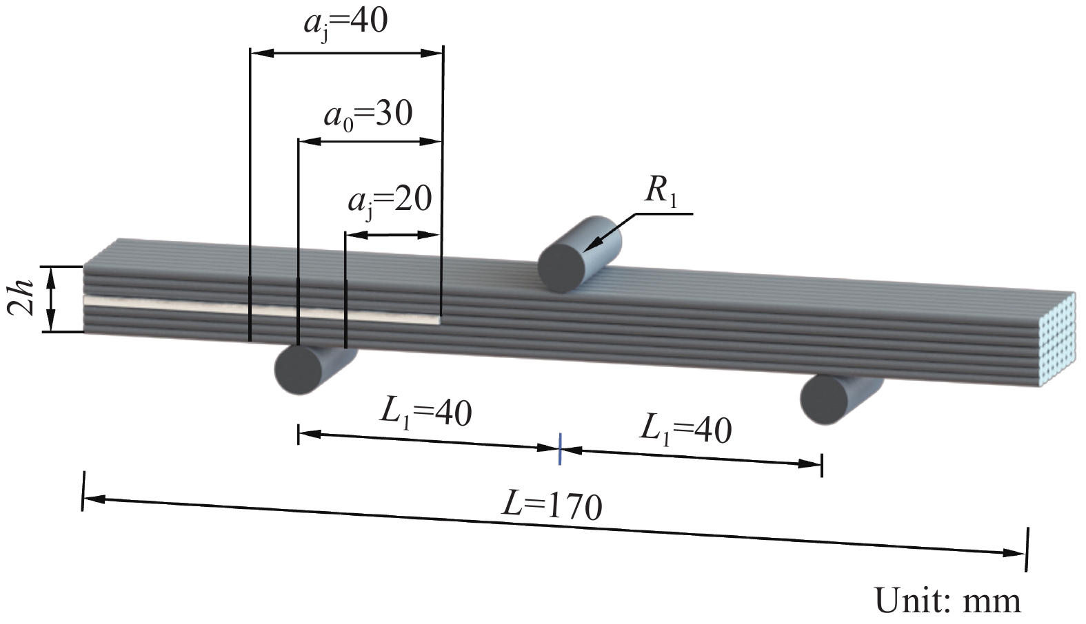
图 1 增材制造CFRP试件的几何特征
Figure 1. Geometric characteristics of additive manufacturing CFRP
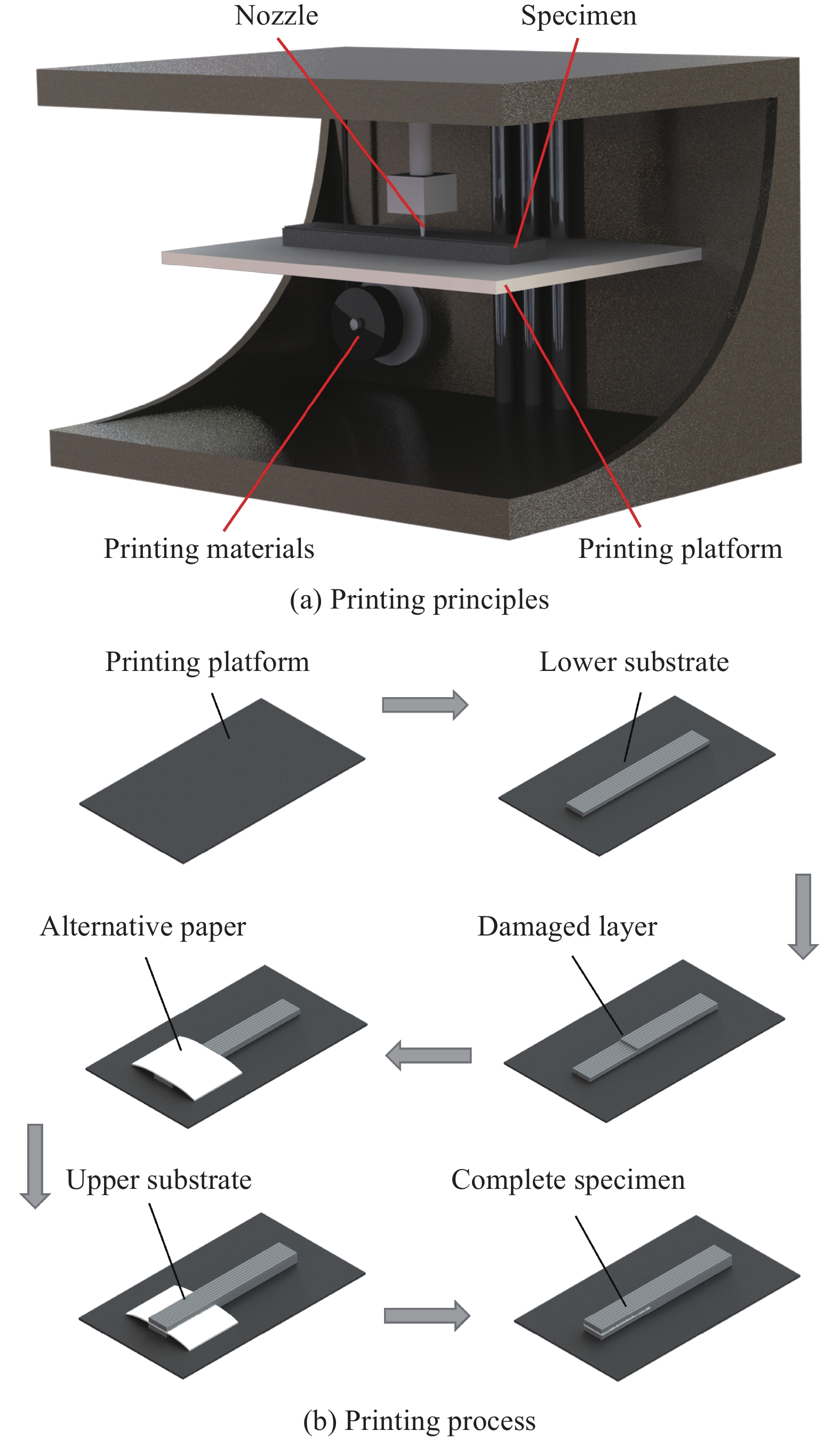
![]()
图 3 增材制造CFRP预制裂纹试件打印原理
Figure 3. Printing principles of additive manufacturing CFRP pre-crack specimen
![]()
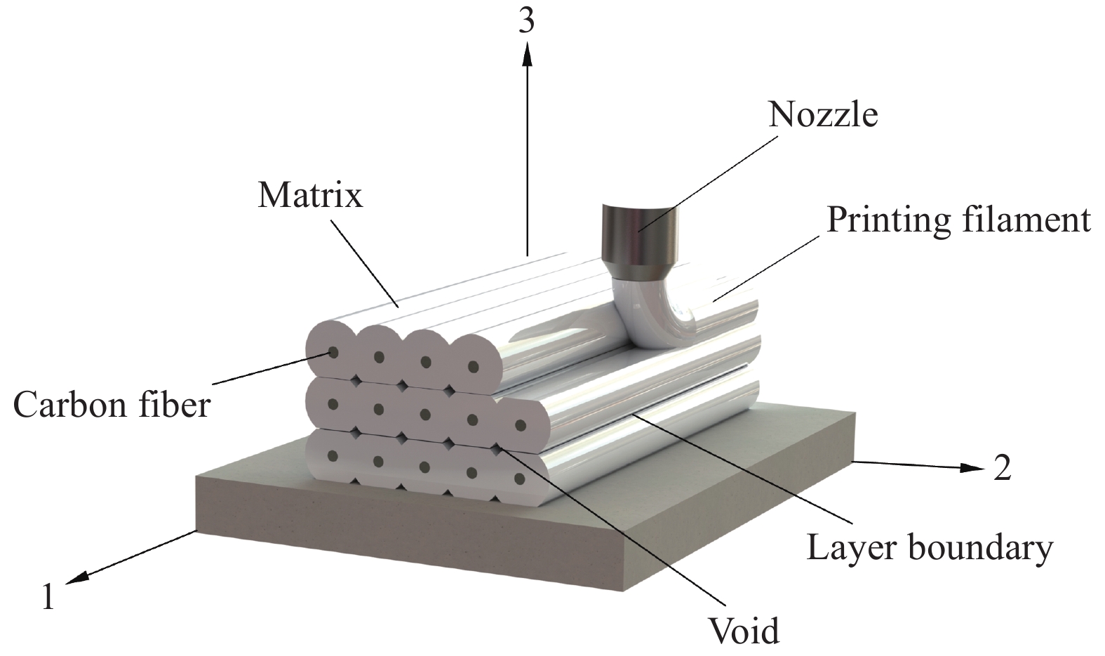
图 5 增材制造CFRP细观结构几何模型
Figure 5. Meso-structures geometric model of additive manufacturing CFRP
![]()
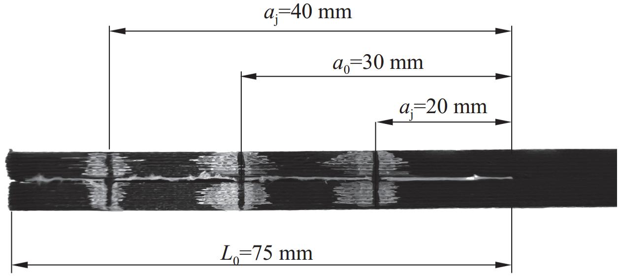
图 6 增材制造CFRP试件校准位置
aj—Layered length of flexibility calibration method; a0—Length of the initial crack; L0—Precast crack length
Figure 6. Calibration locations of additive manufacturing CFRP specimen
![]()
图 9 增材制造CFRP-II型层间断裂加载过程
Figure 9. Mode II inter-layer fracture loading process of additive manufacturing CFRP
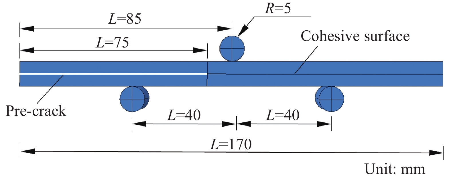
![]()
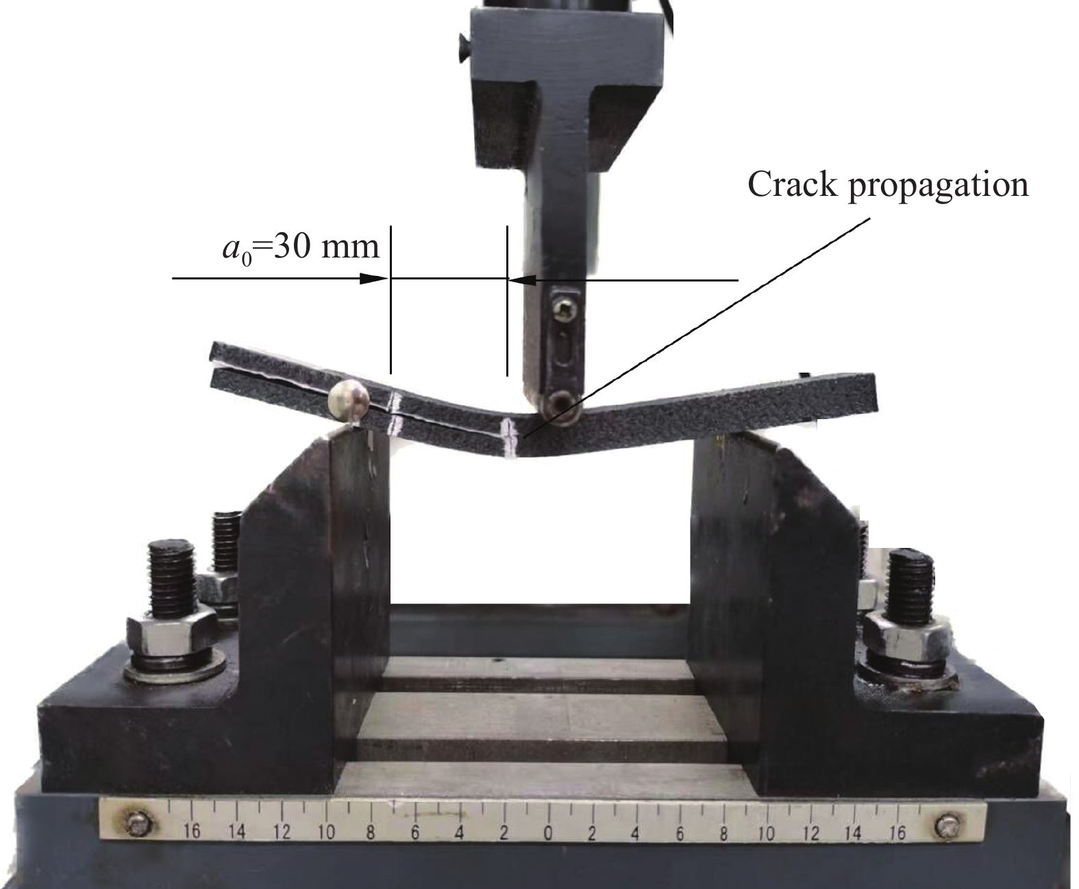
图 7 增材制造CFRP试件加载特征
h—Half of the thickness of the specimen; R1—Fixture radius; L1—Axis distance between lower fixture and upper fixture; L—Length of specimen
Figure 7. Loading characteristics of additive manufacturing CFRP specimen
![]()
图 8 增材制造CFRP试件柔度校准试验
Figure 8. Compliance calibration test of additive manufacturing CFRP specimen
![]()
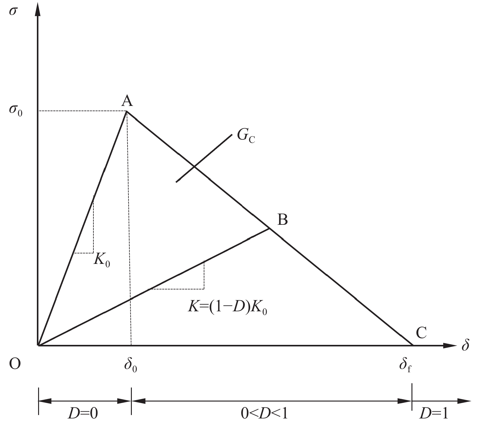
图 10 内聚区双线性本构模型
σ—Stress; δ—Displacement; σ0—Layered damage initiation stress; δ0—Initial displacement of delamination damage; δf—Displacement corresponding to complete layering of materials; K0—Initial interface stiffness; K—Damage interface stiffness; D—Damage variable; GC—Fracture toughness
Figure 10. Bilinear constitutive model of cohesive zone
![]()
图 11 增材制造CFRP预制裂纹试件端部缺口梁三点弯曲(ENF)试验仿真模型
Figure 11. End notched flexure (ENF) experiment simulation model of additive manufacturing CFRP pre-crack specimen
![]()
图 13 不同网格尺寸的计算结果对比
Figure 13. Comparison of calculation results with different mesh sizes
![]()
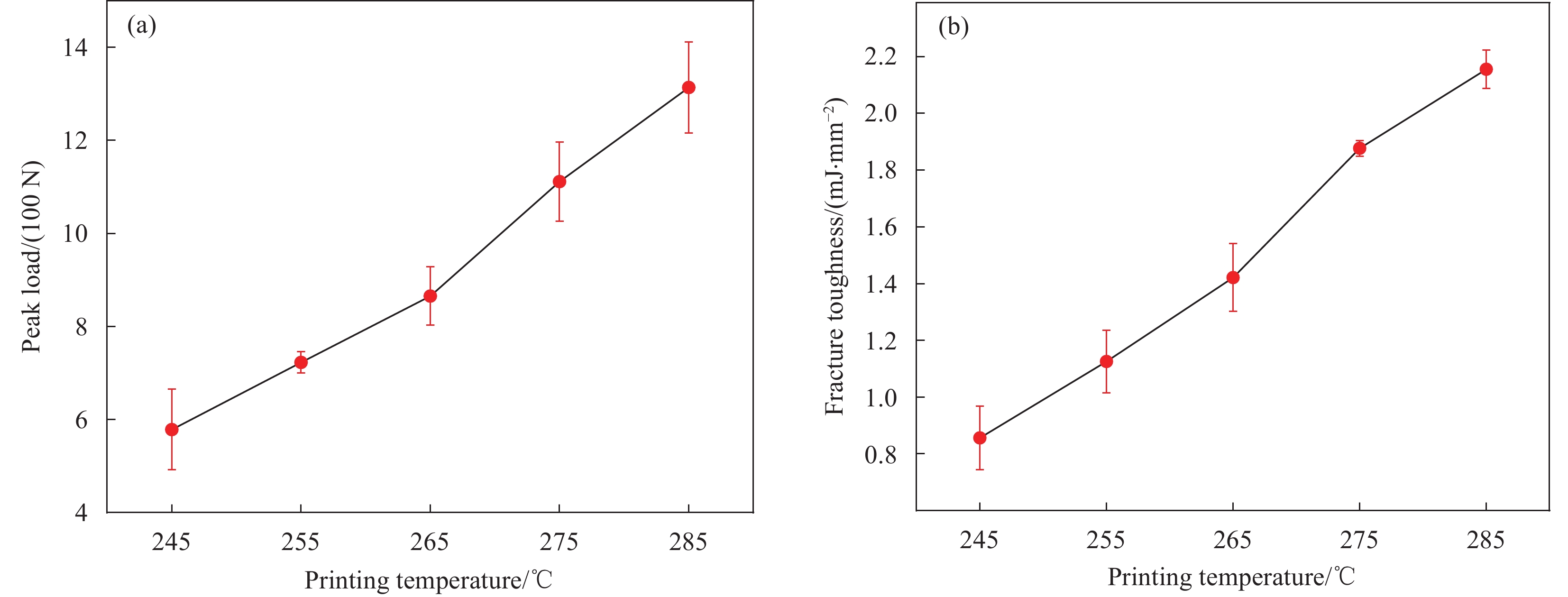
图 14 打印速度40 mm/s下不同打印温度时增材制造CFRP荷载-位移曲线:(a) 245℃;(b) 255℃;(c) 265℃;(d) 275℃;(e) 285℃
Figure 14. Load-displacement curves of additive manufacturing CFRP with printing speed of 40 mm/s under different printing temperatures: (a) 245℃; (b) 255℃; (c) 265℃; (d) 275℃; (e) 285℃
![]()
图 15 打印速度40 mm/s下增材制造CFRP层间力学性能变化规律:(a) 荷载峰值;(b) 断裂韧性值
Figure 15. Variations of inter-layer mechanical properties of additive manufacturing CFRP with printing speed of 40 mm/s: (a) Peak load; (b) Fracture toughness
![]()
图 16 打印速度40 mm/s下增材制造CFRP的细观结构
Figure 16. Meso-structures of additive manufacturing CFRP with printing speed of 40 mm/s
![]()
图 17 打印温度275℃下不同打印速度时增材制造CFRP荷载-位移曲线:(a) 20 mm/s;(b) 30 mm/s;(c) 40 mm/s;(d) 50 mm/s;(e) 60 mm/s
Figure 17. Load-displacement curves of additive manufacturing CFRP with printing temperature of 275℃ under different printing speeds: (a) 20 mm/s; (b) 30 mm/s; (c) 40 mm/s; (d) 50 mm/s; (e) 60 mm/s
![]()
图 18 打印温度275℃下增材制造CFRP层间力学性能变化规律:(a) 荷载峰值;(b) 断裂韧性值
Figure 18. Variation of inter-layer mechanical properties for additive manufacturing CFRP with printing temperature of 275℃: (a) Peak load; (b) Fracture toughness
![]()
图 19 打印温度275℃下增材制造CFRP的细观结构
Figure 19. Meso-structures of additive manufacturing CFRP with printing temperature of 275℃
![]()
图 20 打印速度40 mm/s下不同打印温度时增材制造CFRP荷载-位移曲线仿真结果与试验数据对比:(a) 245℃;(b) 255℃;(c) 265℃;(d) 275℃;(e) 285℃
Figure 20. Comparison between simulation results and test data of load-displacement curves of additive manufacturing CFRP with printing speed of 40 mm/s under different printing temperatures: (a) 245℃; (b) 255℃; (c) 265℃; (d) 275℃; (e) 285℃
![]()
图 21 打印温度275℃下不同打印速度时增材制造CFRP荷载-位移曲线仿真结果与试验数据对比:(a) 20 mm/s;(b) 30 mm/s;(c) 40 mm/s;(d) 50 mm/s;(e) 60 mm/s
Figure 21. Comparison between simulation results and test data of load displacement curves of additive manufacturing CFRP with printing temperature of 275℃ under different printing speeds: (a) 20 mm/s; (b) 30 mm/s; (c) 40 mm/s; (d) 50 mm/s; (e) 60 mm/s
表 1 增材制造碳纤维增强树脂基复合材料(CFRP)的物理性能
Table 1 Physical properties of additive manufacturing carbon fiber reinforced polymer (CFRP)
Test condition Property Value ASTM D792[20] Density/(g·cm−3) 1.17 DSC[21], 10℃/min Vitrification temperature/℃ 56.6 300℃, 2.16 kg Melt index/(g·min−1) 205 DSC[21], 10℃/min Melting point/℃ 220 DSC[21], 10℃/min Crystallization temperature/℃ 186.6 ISO 75[22], 1.8 MPa Thermal deformation/℃ 196 Note: DSC—Differential scanning calorimetry.  下载: 导出CSV
表 2 增材制造CFRP固定打印参数
Table 2 Fixed printing parameters of additive manufacturing CFRP
Parameter Value Layer height/mm 0.2 Heated build platform temperature/℃ 90 Filling rate/% 99 Filling shape Linear Filling overlap rate/% 5 Nozzle diameter/mm 0.4
下载: 导出CSV
表 3 增材制造CFRP变量打印参数
Table 3 Variable printing parameters of additive manufacturing CFRP
Temperature/℃ Speed/(mm·s–1) 245, 255, 265, 275, 285 20, 30, 40, 50, 60
下载: 导出CSV
表 4 不同工况下的界面刚度K0及界面强度σ0
Table 4 Interface stiffness K0 and interface strength σ0 with different working conditions
Printing
temperature/℃Printing speed/
(mm·s−1)K0/(MPa·mm−1) σ0/MPa Printing
temperature/℃Printing speed/
(mm·s−1)K0/(MPa·mm−1) σ0/MPa 245 40 1.8×10³ 16 275 20 1.7×10³ 17 255 2.6×10³ 19 30 2.4×10³ 21 265 2.7×10³ 22 50 3.3×10³ 26 275 3.0×10³ 24 60 3.7×10³ 28 285 3.3×10³ 28
下载: 导出CSV
表 5 不同网格尺寸下的计算用时及最大荷载对比
Table 5 Comparisons of calculation time and maximum load with different mesh sizes
Mesh size/mm Number of units CPU calculation time/s Maximum load/N 4 3472 1218 1105.031 3 3640 1390 1111.864 2 7680 2334 1116.225 Note:CPU—Computer processor.
下载: 导出CSV
表 6 不同打印温度下试件荷载峰值
Table 6 Peak loads of specimens with different printing temperatures
Peak load/N 245℃ 255℃ 265℃ 275℃ 285℃ Specimen I 674.043 736.153 853.720 1083.141 1211.012 Specimen II 504.145 696.142 809.258 1044.133 1324.143 Specimen Ⅲ 557.234 736.214 933.317 1207.024 1406.043 Average value 578.474 722.836 865.432 1111.433 1313.733 Standard deviation 70.968 18.876 50.220 69.444 79.961
下载: 导出CSV
表 7 不同打印温度下试件峰值力位移
Table 7 Peak load displacements of specimens with different printing temperatures
Peak load displacement/mm 245℃ 255℃ 265℃ 275℃ 285℃ Specimen I 29.365 29.988 27.953 31.683 35.158 Specimen II 25.232 27.474 30.841 33.293 34.436 Specimen Ⅲ 28.773 30.695 26.279 30.136 33.596 Average value 27.790 29.284 28.358 31.704 34.397 Standard deviation 1.825 1.429 1.675 1.289 0.638
下载: 导出CSV
表 8 不同打印温度下试件断裂韧性值
Table 8 Fracture toughness of specimens with different printing temperatures
Fracture toughness/(mJ·mm−2) 245℃ 255℃ 265℃ 275℃ 285℃ Specimen I 0.983 1.086 1.459 1.850 2.098 Specimen II 0.814 1.041 1.287 1.876 2.138 Specimen Ⅲ 0.772 1.250 1.518 1.905 2.231 Average value 0.856 1.126 1.421 1.877 2.156 Standard deviation 0.091 0.090 0.098 0.022 0.056
下载: 导出CSV
表 9 不同打印速度下试件荷载峰值
Table 9 Peak loads of specimens with different printing speeds
Peak load/N 20 mm/s 30 mm/s 40 mm/s 50 mm/s 60 mm/s Specimen I 1045.134 868.359 1083.021 1167.156 1271.056 Specimen II 880.102 919.665 1044.359 1101.876 1378.168 Specimen Ⅲ 784.413 751.864 1207.189 1206.341 1189.058 Average value 903.216 846.629 1111.523 1158.458 1279.427 Standard deviation 107.687 70.806 69.463 43.089 77.430
下载: 导出CSV
表 10 不同打印速度下试件峰值力位移
Table 10 Peak load displacements of specimens with different printing speeds
Peak load displacement/mm 20 mm/s 30 mm/s 40 mm/s 50 mm/s 60 mm/s Specimen I 31.302 31.711 31.683 31.899 34.281 Specimen II 26.290 30.126 33.293 33.451 32.507 Specimen Ⅲ 29.075 32.883 30.136 30.541 35.929 Average value 28.889 31.573 31.704 31.964 34.239 Standard deviation 2.050 1.130 1.289 1.189 1.397
下载: 导出CSV
表 11 不同打印速度下试件断裂韧性值
Table 11 Fracture toughness of specimens with different printing speeds
Fracture toughness/(mJ·mm−2) 20 mm/s 30 mm/s 40 mm/s 50 mm/s 60 mm/s Specimen I 1.473 1.727 1.850 1.920 2.018 Specimen II 1.491 1.678 1.876 2.155 2.038 Specimen Ⅲ 1.555 1.826 1.905 1.905 2.258 Average value 1.506 1.744 1.877 1.993 2.105 Standard deviation 0.035 0.062 0.022 0.114 0.109
下载: 导出CSV
表 12 变温度工况下增材制造CFRP力学性能仿真结果与试验数据的对比分析
Table 12 Comparison between simulation results and test data of additive manufacturing CFRP mechanical properties with variable temperature conditions
Working conditions
and parameters/(℃-mm·s−1)Peak load/N Relative error/% Peak load displacement/mm Relative error/% 245-40 Test date 674.043 1.1730 29.365 4.734 Simulation result 685.920 27.975 255-40 Test date 736.214 0.6260 29.988 3.645 Simulation result 740.854 28.895 265-40 Test date 853.720 1.7145 27.953 8.664 Simulation result 839.083 25.531 275-40 Test date 1083.141 3.7450 31.683 9.245 Simulation result 1125.282 28.754 285-40 Test date 1211.012 2.0570 35.158 8.283 Simulation result 1236.447 32.246
下载: 导出CSV
表 13 变速度工况下增材制造CFRP力学性能仿真结果与试验数据的对比分析
Table 13 Comparison between simulation results and test data of additive manufacturing CFRP mechanical properties with variable speed conditions
Working conditions
and parameters/(℃-mm·s−1)Peak load/N Relative error/% Peak load displacement/mm Relative error/% 275-20 Test date 880.102 1.477 29.075 2.102 Simulation result 893.294 28.464 275-30 Test date 868.359 0.678 31.711 4.055 Simulation result 874.284 30.425 275-40 Test date 1083.141 3.745 31.683 9.245 Simulation result 1125.282 28.754 275-50 Test date 1167.156 2.895 31.899 8.483 Simulation result 1201.949 29.193 275-60 Test date 1271.056 3.095 34.281 6.677 Simulation result 1311.648 31.992
下载: 导出CSV
-
[1] 龙昱, 李岩, 付昆昆. 3D打印纤维增强复合材料工艺和力学性能研究进展[J]. 复合材料学报, 2022, 39(9): 4196-4212. LONG Yu, LI Yan, FU Kunkun. Research progress in the process and mechanical properties of 3D printed fiber reinforced composite materials[J]. Acta Materiae Compositae Sinica, 2022, 39(9): 4196-4212(in Chinese).
[2] 曹丰, 曾志勇, 黄建, 等. 连续纤维增强复合材料的3D打印工艺及应用进展[J]. 中国科学: 技术科学, 2023, 50(11): 1815-1833. CAO Feng, ZENG Zhiyong, HUANG Jian, et al. Printing process and application progress of 3D printing continuous fiber reinforced composites[J]. Scientia Sinica (Technologica), 2023, 50(11): 1815-1833(in Chinese).
[3] 张聘, 王奉晨, 李玥萱, 等. 连续纤维增强复合材料3D打印技术现状及展望[J]. 航空制造技术, 2023, 66(16): 76-87. ZHANG Pin, WANG Fengchen, LI Yuexuan, et al. Status and prospects of 3D printing for continuous fiber reinforced composites[J]. Aeronautical Manufacturing Technology, 2023, 66(16): 76-87(in Chinese).
[4] 刘强, 马小康, 宗志坚. 斜纹机织碳纤维/环氧树脂复合材料性能及其在电动汽车轻量化设计中的应用[J]. 复合材料学报, 2011, 28(5): 83-88. LIU Qiang, MA Xiaokang, ZONG Zhijian. Performance of twill woven carbon fiber/epoxy resin composite material and its application in lightweight design of electric vehicles[J]. Acta Materiae Compositae Sinica, 2011, 28(5): 83-88(in Chinese).
[5] 车士俊, 张明睿. 复合材料在轨道交通中的应用综述[J]. 纤维复合材料, 2022, 39(2): 100-104. DOI: 10.3969/j.issn.1003-6423.2022.02.019 CHE Shijun, ZHANG Mingrui. Overview of the application of composite materials in rail transit[J]. Fiber Composite Materials, 2022, 39(2): 100-104(in Chinese). DOI: 10.3969/j.issn.1003-6423.2022.02.019
[6] 赵丽滨, 龚愉, 张建宇. 纤维增强复合材料层合板分层扩展行为研究进展[J]. 航空学报, 2019, 40(1): 171-199. ZHAO Libin, GONG Yu, ZHANG Jianyu. Research progress on delamination propagation behavior of fiber reinforced composite laminates[J]. Chinese Journal of Aeronautics, 2019, 40(1): 171-199(in Chinese).
[7] LIU T F, TIAN X Y, ZHANG M Y, et al. Interfacial performance and fracture patterns of 3D printed continuous carbon fiber with sizing reinforced PA6 composites[J]. Composites Part A: Applied Science and Manufacturing, 2018, 114: 368-376. DOI: 10.1016/j.compositesa.2018.09.001
[8] LIU T F, TIAN X Y, ZHANG Y Y, et al. High-pressure interfacial impregnation by micro-screw in-situ extrusion for 3D printed continuous carbon fiber reinforced nylon composites[J]. Composites Part A: Applied Science and Manufacturing, 2020, 130: 105770. DOI: 10.1016/j.compositesa.2020.105770
[9] TIAN X Y, LIU T F, YANG C C, et al. Interface and performance of 3D printed continuous carbon fiber reinforced PLA composites[J]. Composites Part A: Applied Science and Manufacturing, 2016, 88: 198-205. DOI: 10.1016/j.compositesa.2016.05.032
[10] LUO M, TIAN X Y, SHANG J F, et al. Impregnation and interlayer bonding behaviours of 3D-printed continuous carbon-fiber-reinforced poly-ether-ether-ketone composites[J]. Composites Part A: Applied Science and Manufacturing, 2019, 121: 130-138. DOI: 10.1016/j.compositesa.2019.03.020
[11] LUO M, TIAN X Y, SHANG J F, et al. Bi-scale interfacial bond behaviors of CCF/PEEK composites by plasma-laser cooperatively assisted 3D printing process[J]. Composites Part A: Applied Science and Manufacturing, 2020, 131: 105812. DOI: 10.1016/j.compositesa.2020.105812
[12] IRAGI M, PASCUAL-GONZALEZ C, ESNAOLA A, et al. Ply and interlaminar behaviours of 3D printed continuous carbon fiber-reinforced thermoplastic laminates: Effects of processing conditions and microstructure[J]. Additive Manufacturing, 2019, 30: 100884. DOI: 10.1016/j.addma.2019.100884
[13] CAMINERO M A, CHACON J M, GARCIA MOERNO I, et al. Interlaminar bonding performance of 3D printed continuous fiber reinforced thermoplastic composites using fused deposition modelling[J]. Polymer Testing, 2018, 68: 415-423. DOI: 10.1016/j.polymertesting.2018.04.038
[14] YAVAS D, ZHANG Z, LIU Q, et al. Interlaminar shear behavior of continuous and short carbon fiber reinforced polymer composites fabricated by additive manufacturing[J]. Composites Part B: Engineering, 2021, 204: 108460. DOI: 10.1016/j.compositesb.2020.108460
[15] SOMIREDDY M, SINGH C V, CZEKANSKI A. Mechanical behaviour of 3D printed composite parts with short carbon fiber reinforcements[J]. Engineering Failure Analysis, 2019, 107: 104232.
[16] KONG X, LUO J, LUO Q, et al. Experimental study on interface failure behavior of 3D printed continuous fiber reinforced composites[J]. Additive Manufacturing, 2022, 59: 103077. DOI: 10.1016/j.addma.2022.103077
[17] CAI R, WEN W, WANG K, et al. Tailoring interfacial properties of 3D-printed continuous natural fiber reinforced polypropylene composites through parameter optimization using machine learning methods[J]. Materials Today Communications, 2022, 32: 103985. DOI: 10.1016/j.mtcomm.2022.103985
[18] TOUCHARD F, CHOCINSKI-ARNAULT L, FOURNIER T, et al. Interfacial adhesion quality in 3D printed continuous CF/PA6 composites at filament/matrix and interlaminar scales[J]. Composites Part B: Engineering, 2021, 218: 108891. DOI: 10.1016/j.compositesb.2021.108891
[19] DANG Z, CAO J, PAGANI A, et al. Fracture toughness determination and mechanism for mode-I interlaminar failure of 3D-printed carbon-Kevlar composites[J]. Composites Communications, 2023, 39: 101532. DOI: 10.1016/j.coco.2023.101532
[20] ASTM International. Standard test methods for density and specific gravity (relative density) of plastics by displacement: ASTM D792—2008[S]. West Conshohocken, PA: ASTM International, 2008.
[21] 中华人民共和国标准化管理局, 国家质量监督检验检疫总局. 塑料差示扫描量热法(DSC) 第3部分:温度、熔化和结晶焓的测定: GB/T 19466.3—2004[S]. 北京: 中国标准出版社, 2004. Standardization Administration of the People's Republic of China, State Administration of Quality Supervision, Inspection and Quarantine. Plastic—Differential scanning calorimetry (DSC)—Part 3: Determination of temperature and enthalpy of melting and crystallization: GB/T 19466.3—2004[S]. Beijing: Standards Press of China, 2004(in Chinese).
[22] International Organization for Standardization. Plastics—Determination of temperature of deflection under load—Part 2: Plastics, ebonite and long-fibre-reinforced composite: ISO 75-2—2013[S]. Geneva: ISO Copyright Office, 2013.
[23] ASTM International. Standard test method for mode II interlaminar fracture toughness of unidirectional fiber reinforced polymer matrix composites: ASTM D7905—19[S]. West Conshohocken, PA: ASTM International, 2019.
[24] 王雅娜, 赵魏. 复合材料II型分层ENF试验数据处理方法对比分析[J]. 复合材料科学与工程, 2022(7): 81-92. WANG Yana, ZHAO Wei. Comparative analysis of data processing methods for type II layered ENF testing of composite materials[J]. Composite Materials Science and Engineering, 2022(7): 81-92(in Chinese).
[25] BLACKMAN B R K, BRUNNER A J, WILLIAMS J G. Mode II fracture testing of composites: A new look at an old problem[J]. Engineering Fracture Mechanics, 2006, 73(16): 2443-2455. DOI: 10.1016/j.engfracmech.2006.05.022
[26] QIU Y, CRISFIELD M A, ALFANO G. An interface element formulation for the simulation of delamination with buckling[J]. Engineering Fracture Mechanics, 2001, 68(16): 1755-1776. DOI: 10.1016/S0013-7944(01)00052-2
[27] CAMANHO P, DÁVILA C. Mixed-mode decohesion finite elements for the simulation of delamination in composite materials[R]. Hanover: NASA, 2002, 6: 211737.
[28] TURON A, DAVILA C G, CAMANHO P P, et al. An engineering solution for using coarse meshes in the simulation of delamination with cohesive zone models[R]. Washington: NASA, 2005, 3: 213547.
[29] BORG R, NILSSON L, SIMONSSON K. Simulation of low velocity impact on fiber laminates using a cohesive zone based delamination model[J]. Composites Science & Technology, 2004, 64(2): 279-288.
[30] ALFANO G. On the influence of the shape of the interface law on the application of cohesive-zone models[J]. Composites Science and Technology, 2006, 66(6): 723-730. DOI: 10.1016/j.compscitech.2004.12.024
[31] ZHAO L B, GONG Y, QIN T L, et al. Failure prediction of out-of-plane woven composite joints using cohesive element[J]. Composite Structures, 2013, 106: 407-416. DOI: 10.1016/j.compstruct.2013.06.017
-
其他相关附件
-
目的
增材制造技术的出现为持续推进碳纤维增强树脂复合材料(Carbon fiber reinforced polymer-CFRP)应用于桥梁工程领域提供了全新思路,然而,增材制造CFRP层间力学性能研究较为薄弱,严重阻碍了该技术在桥梁结构中的应用。为实现增材制造CFRP-Ⅱ型层间断裂韧性的测试分析,并量化打印参数对Ⅱ型层间断裂韧性的影响规律,本文分别从试验及仿真分析两个方面展开了相关研究。
方法首先,对打印工艺进行优化并提出了一种新型层间预制裂纹制备方法,即缺层置换法,并利用该方法探索了打印温度、打印速度两类关键打印参数对增材制造CFRP-Ⅱ型层间断裂韧性的影响规律。其次,基于内聚区理论建立了不同打印工况下预制裂纹试件端部缺口梁三点弯曲(End notched flexure-ENF)试验的仿真模型,并完成了仿真结果与试验数据的对比分析。最后,通过扫描电镜获取了不同打印参数下增材制造CFRP试件面1及面2的细观结构,并合理解释了打印参数对Ⅱ型层间断裂韧性的影响机理。
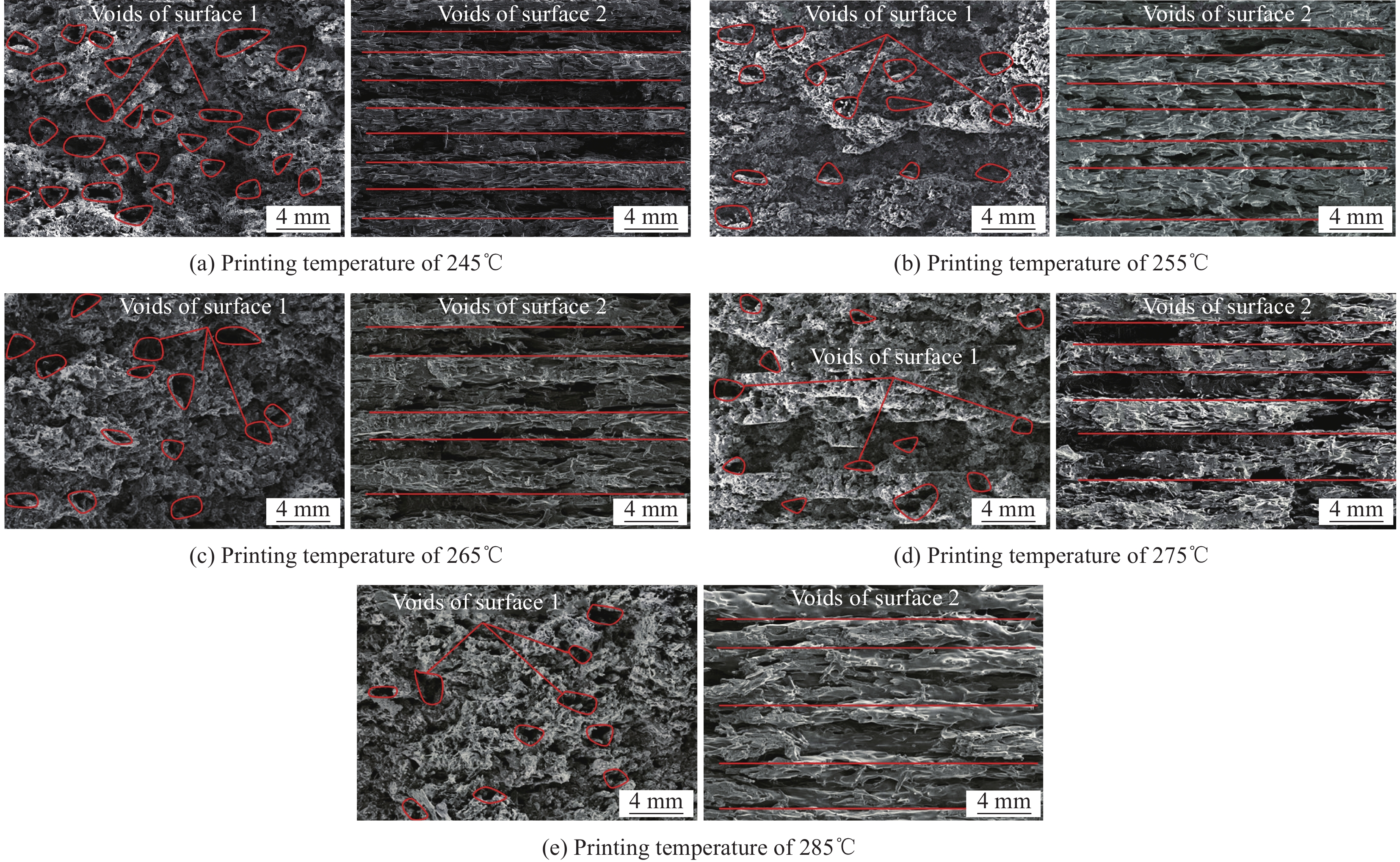
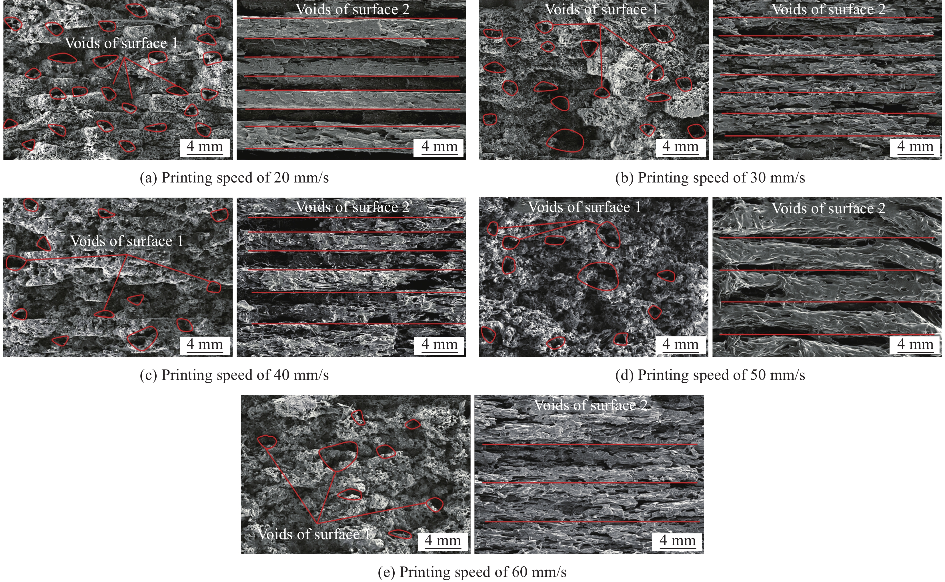
结果关于打印温度:①随着打印温度的升高,试件层间界面的抗剪切能力得到提升。当打印温度从245℃提升至285℃,试验荷载峰值的变化幅度范围为18%~27%,层间断裂韧性的变化幅度范围为14%~32%。②打印温度越高,试件层间延性越大,且当打印温度为285℃时,试件具有与传统加工工艺复合材料相近的断裂韧性。③当打印速度恒定时打印温度越高,丝材固化时间越长,固化前会发生充分的塑性流动,减小了打印丝内部及打印丝之间的空隙。同时,铺设下一层打印丝时,上一层打印丝温度越高,层与层之间材料的分子间作用效果越明显,表现为层间粘结性能增强。由此可得,当打印速度不变时材料的层间力学性能会随着打印温度的升高而增强。关于打印速度:①随着打印速度的提高,试件层间抗剪切能力也提高,增幅较大。当打印速度从20mm/s提升至60mm/s,试验荷载峰值的变化幅度范围为4%~31%,层间断裂韧性的变化幅度范围为4%~16%。②打印速度越高,试件层间断裂韧性越大,且当打印速度为60mm/s时,试件具有与传统加工工艺复合材料相近的断裂韧性。③当打印温度恒定时打印速度越快,丝材沉积过程中散失的热量越少,已沉积丝材与新挤出丝材在固化前能充分的发生塑性流动,打印丝之间的粘结性能越强。此外,铺设下一层打印丝时,上一层打印丝温度散失较少,层与层之间材料的分子间作用效果越明显,表现为层间粘结能力增强。由此可得,当打印温度不变时材料的层间力学性能会随着打印速度的升高而增强。
结论①打印温度及速度均会对增材制造CFRP-Ⅱ型层间力学性能产生明显的影响。②本文仿真结果与试验数据之间的相对误差基本保持在10%以内,表明了本次提出的缺层置换法是可靠的。③缺陷是影响材料层间力学性能的关键因素,随着打印温度及速度的提高,孔洞等缺陷的数量更少,可以获得更好的层间力学性能。
-
碳纤维增强树脂基复合材料(Carbon fiber reinforced polymer-CFRP)为高性能材料,具有高比刚度/强度、耐腐蚀/疲劳的优势,用于桥梁工程已成为目前的研究热点,而传统工艺(热压法、层压法等)存在的开发模具昂贵等问题严重制约了其相关应用。增材制造技术的出现为持续推进CFRP应用于桥梁工程领域提供了全新思路,然而,增材制造CFRP的层间力学性能研究较为薄弱,严重阻碍了该技术在桥梁结构中的应用。
本文将研究对象选取为增材制造CFRP,提出了一种新型层间预制裂纹制备方法,即缺层置换法,并利用该方法探索了两类关键打印参数对增材制造CFRP-Ⅱ型层间断裂韧性的影响规律,结果表明打印温度对层间力学性能的影响更强。同时,仿真结果与试验数据的相对误差均保持在10%以内,表明本次所获试验数据合理且稳定,故缺层置换法可用于制备增材制造CFRP预制裂纹试件,且传统工艺复合材料仿真方法同样适用于增材制造CFRP的仿真分析。进一步,结合扫描电镜(Scanning electron microscope-SEM)结果,揭示了两类关键打印参数对层间力学性能的影响机制,并为通过优化打印工艺提高材料层间力学性能提供了建议。
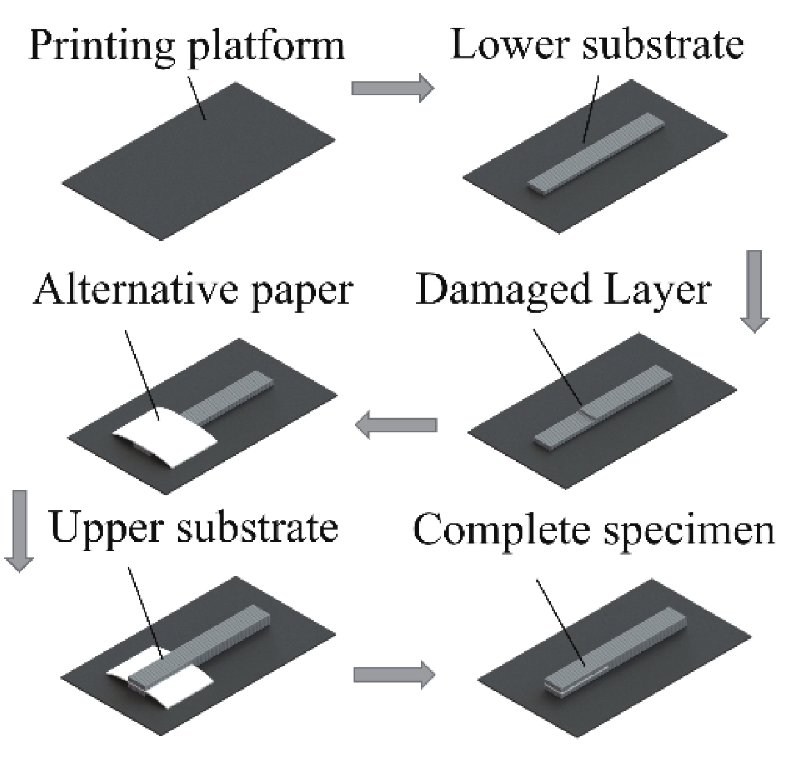
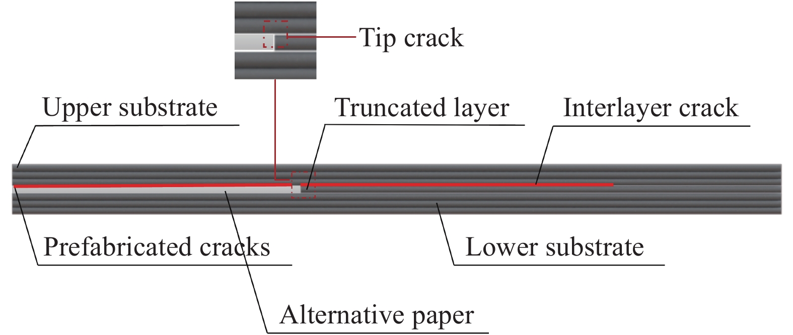
增材制造CFRP预制裂纹试件打印过程
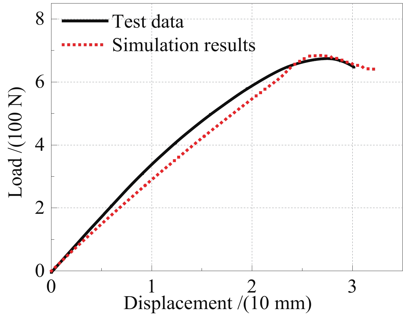
增材制造CFRP荷载-位移曲线仿真结果与试验数据对比分析


计量
- 文章访问数: 224
- HTML全文浏览量: 138
- PDF下载量: 21
