

Mechanics theories for composite materials
-
摘要: 各向同性材料的力学理论已基本完善,但各向异性复合材料的力学理论除线弹性外,皆未成熟,尤其破坏和强度分析,依然还是固体力学面临的一个最大挑战。在过去25年中,为推动复合材料力学学科发展,作者创建了一系列解析理论,包括任意连续纤维、短纤维及颗粒增强复合材料的本构与内应力计算理论-桥联模型,将基体均值应力转换到真实值的真实应力理论,基于物理原理建立的基体破坏准则,预报任意层合结构层间开裂或分层的层间基体应力修正法及超弹性材料的增量型本构理论。基于这些理论,几乎所有两相复合材料的破坏问题,皆有望通过解析公式获得有效解决,只要该复合材料的孔隙率可忽略。其中,桥联模型已得到国内外同行广泛认可,他人应用该理论公开发表的研究论文,已超过250篇。基体真实应力理论,尽管前不久才建立起来,他人应用也已达20篇。本文简要介绍了作者建立的这些理论及如何据此解决众多复合材料挑战性问题。Abstract: Whereas mechanics theories for isotropic materials have been nearly matured, essentially only the linear elasticity theories for anisotropic composite materials are well established. All of the other mechanical behaviors of the composites are not well understood. Specifically, the failure and strength analysis for the composites still remains to be one of the greatest challenges in solid mechanics. During the last 25 years, in order to advance the development in the mechanics of composite materials, this author has established a series of analytical theories. They include the constitutive and internal stress calculation theory, named Bridging Model, for composites reinforced with continuous or short fibers or particles, the true stress theory for converting a homogenized stress of the matrix in a composite into a true value, the failure criteria for matrix failures established on a physics based principle, the interlaminar matrix stress modification method for predicting interlaminar fracture or delamination of any laminated structure, and the incremental constitutive relation for hyperelastic materials. Based on these theories, almost all of the failure problems of two-phase composites can be efficiently resolved through analytical formulae, as long as void contents in the composites can be neglected. Amongst, Bridging Model has been known world-widely, and more than 250 publications have been made by people other than the author’s group using Bridging Model as a theoretical tool. Furthermore, the others’ publications based on the matrix true stress theory have reached a number of 20, although this theory has been established only recently by the author. A brief summary on the establishment of the author’s theories and how to apply them to resolve challenging problems in composites and their structures is presented in the paper.
-
3D机织复合材料具有优异的抗分层、抗冲击、耐疲劳性能及复杂构件近净成型等优点,在航空航天、海洋船舶、军事、建筑、车辆工程和体育等领域得到了广泛应用[1-2]。近年来,人们对大尺寸、复杂外形的3D机织复合材料提出了更多的应用需求[3-4]。
预制体的纤维结构对复合材料的力学性能有着决定性的影响,在大尺寸、异形复合材料结构件的制备过程中,预制体往往发生复杂的外形转换,其中弯曲变形是一种常见的变形模式[5-7]。研究表明,预制体的弯曲性能对变形过程中褶皱缺陷的形成、演化及最终形态有着决定性影响。弯曲性能是影响预制体适形性能和复合材料力学性能的重要因素[8-10]。
实验是研究预制体力学性能的最直接手段。目前预制体弯曲性能的测试方法主要包括Peirce悬臂弯曲、Kawabata弯曲及三点弯曲[11]。在Peirce悬臂弯曲测试中,预制体在自身重力作用下发生弯曲,并接触到特定倾角的斜面,通过测量悬臂长度计算弯曲刚度[12-13]。Bilbao等[14]设计了一种利用光学技术测量织物弯曲变形的悬臂梁实验方法,测试装置由两个模块组成:机械模块能够在自身质量下将样品置于悬臂结构中,也可以在样品的自由边缘添加质量,达到更大的曲率;光学模块可以拍摄弯曲试样的形状,通过图像处理计算试样的弯曲曲率。传统悬臂梁试验中预制体由于载荷分布不均有可能出现扭转现象。针对这一问题,Dangora等[15]采用垂直悬臂梁法对预制体进行了弯曲测试,该方法将预制体竖直悬挂,通过绑在自由端的绳子施加载荷,使用数码相机记录试样的位移并计算弯曲曲率。悬臂弯曲试样容易制备、实验操作简单,但高厚度预制体很难在自身重力作用下发生较大的弯曲变形,需要额外施加一定的载荷,容易造成较大误差[16]。Kawabata弯曲实验将试样夹持在特定的夹具中,通过旋转夹具实现试样的弯曲变形。Kawabata弯曲方法能够实现试样的往复弯曲-展平变形,获取试样的弯矩-曲率曲线,表征织物的非线性弯曲变形行为[17]。Ropers等[18]和Sachs等[19]在Kawabata弯曲法的基础上开发了一种基于流变仪的测试方法,可以实现摆动式旋转加载,这种加载方式同样能够确保试样发生纯弯曲变形。目前的Kawabata弯曲实验往往适用于较小尺寸的试样,难以保障大尺寸、高厚度试样变形时曲率的均匀性。预制体的三点弯曲测试方法借鉴了复合材料的测试标准,该方法简单易操作,主要适用于具有较大厚度和弯曲刚度的预制体[20]。Charmetant等[21]、Liang等[22]、Boisse等[23]和Margossian等[24]使用三点弯曲法对3D碳纤维层层角联锁预制体的弯曲行为进行了测试,通过光学图像记录弯曲变形前后预制体厚度的变化、计算试样的曲率。结果表明,由于纱线的抗拉刚度较大,预制体弯曲变形主要由横向剪切引起,原本与试样表面垂直的法线在变形之后不再与表面垂直。
目前的预制体弯曲实验主要关注试样的宏观力学响应,包括弯曲变形过程中的载荷、挠度和曲率等,对预制体内部各纱线系统的微细观变形机制仍然缺乏系统性的研究。本文采用三点弯曲实验研究了碳纤维3D机织预制体的弯曲行为。引入临界弯曲能量表征预制体的弯曲变形性能,通过Micro-CT技术观测试样弯曲变形前、后的内部纱线形态,分析预制体的弯曲变形机制,建立经纱密度和纬纱密度与弯曲性能的量化关系,为预制体工艺设计提供理论指导。
1. 试验材料及方法
1.1 原材料
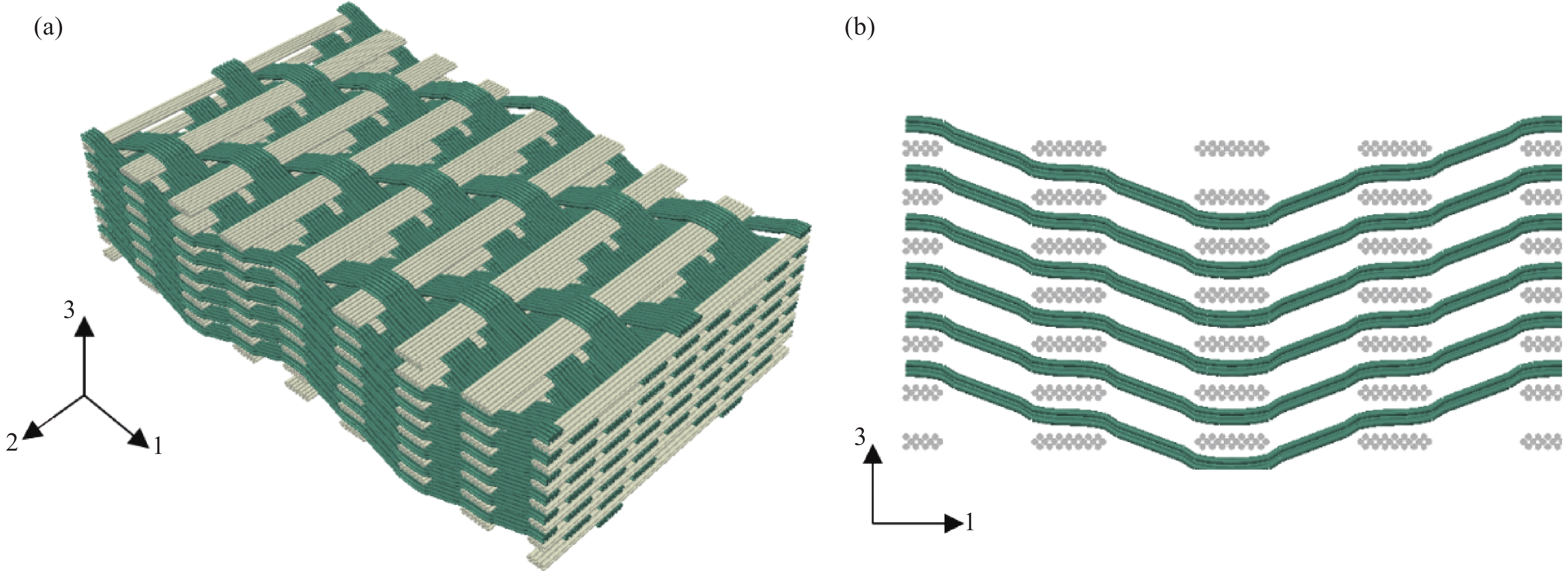
按照3种经纱密度(5.0根/cm、8.0根/cm、10.0根/cm)和3种纬纱密度(2.5根/cm、3.0根/cm、3.5根/cm)制备了9件碳纤维3D机织预制体样件。所有样件的经纱和纬纱均由T800-24 K碳纤维纱线组成,预制体交织方式为一三斜纹层层角联锁结构,如图1所示。预制体内部纬纱呈伸直状态,经纱呈屈曲状态,经、纬纱互相垂直,经纱将纬纱捆绑连接起来。预制体试样的具体参数如表1所示,试样编号中的J表示经纱密度、W表示纬纱密度。例如“J5W2.5”表示该试样经纱密度5根/cm,纬纱密度2.5根/cm。试样设计厚度为5 mm,该厚度指的是该试样被压缩至纤维体积含量55vol%时的厚度,实际上织物在纺织成形后(未受压力的状态下)的实际厚度往往会略高于设计厚度。
![]() 图 1 3D机织预制体示意图:(a) 3D机织结构;(b) 经纱路径Figure 1. Schematic diagrams of 3D woven preform: (a) 3D woven structure; (b) Warp yarn path表 1 3D机织预制体结构参数Table 1. Structure parameters of 3D woven preforms
图 1 3D机织预制体示意图:(a) 3D机织结构;(b) 经纱路径Figure 1. Schematic diagrams of 3D woven preform: (a) 3D woven structure; (b) Warp yarn path表 1 3D机织预制体结构参数Table 1. Structure parameters of 3D woven preformsSample Number of warp layer Number of weft layer Apparent thickness/mm Weaving point density/cm−2 J5W2.5 7 8 6.31 21.88 J5W3.0 6 7 5.89 22.50 J5W3.5 6 7 6.19 26.25 J8W2.5 5 6 6.78 25.00 J8W3.0 5 6 6.60 30.00 J8W3.5 4 5 5.97 28.00 J10W2.5 4 5 6.71 25.00 J10W3.0 4 5 7.00 30.00 J10W3.5 4 5 6.73 35.00 1.2 三点弯曲测试
采用电动裁切机(GD-H690)对预制体进行裁剪。参考标准GB/T 33621—2017[25](三维编织物及其树脂基复合材料弯曲性能试验方法),在岛津实验机(AGS-J1KN)上开展预制体样件的三点弯测试。预制体样件的跨距与厚度之比为8∶1,样件尺寸为100 mm×30 mm×5 mm。将预制体试样放置在三点弯曲支座上,保证左右对称,通过支座上的标尺调节至适当跨距,设定压头加载速率5 mm/min,测试过程中记录载荷-挠度数据。
1.3 Micro-CT测试
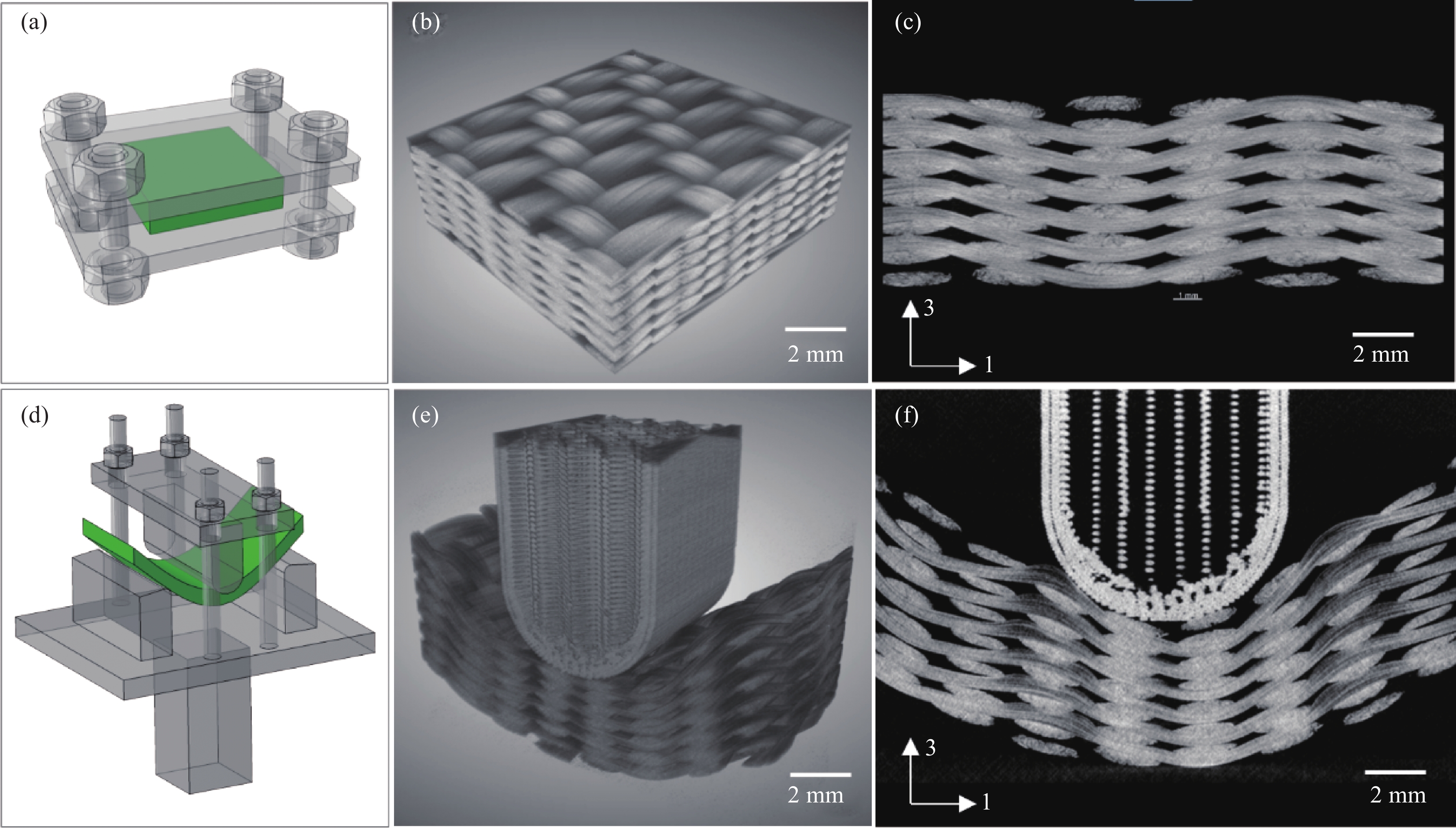
为了研究预制体的弯曲变形机制,通过Micro-CT技术获得样件弯曲变形前、后的内部纤维结构。参考三点弯曲夹具的尺寸设计了一种弯曲控形工装,如图2所示。将预制体试样放入控形工装中,通过调节压头位置可以实现不同程度的弯曲变形,锁紧螺栓使弯曲变形得以“固定”。扫描测试时将预制体试样连同控形工装一起放入Micro-CT扫描设备的观测腔室中。本文采用卡尔蔡司Xradia 510 Versa设备开展Micro-CT测试,X射线源的起始能量设置为80 kV/7 W,曝光时间为1 s,图像分辨率为25 μm。
![]() 图 2 3D机织预制体Micro-CT扫描:((a)~(c)) 变形前;((d)~(f)) 变形后Figure 2. Micro-CT test of the 3D woven preform: ((a)-(c)) Before deformation; ((d)-(f)) After deformation
图 2 3D机织预制体Micro-CT扫描:((a)~(c)) 变形前;((d)~(f)) 变形后Figure 2. Micro-CT test of the 3D woven preform: ((a)-(c)) Before deformation; ((d)-(f)) After deformation2. 三点弯曲测试结果及分析
2.1 3D机织预制体宏观力学响应
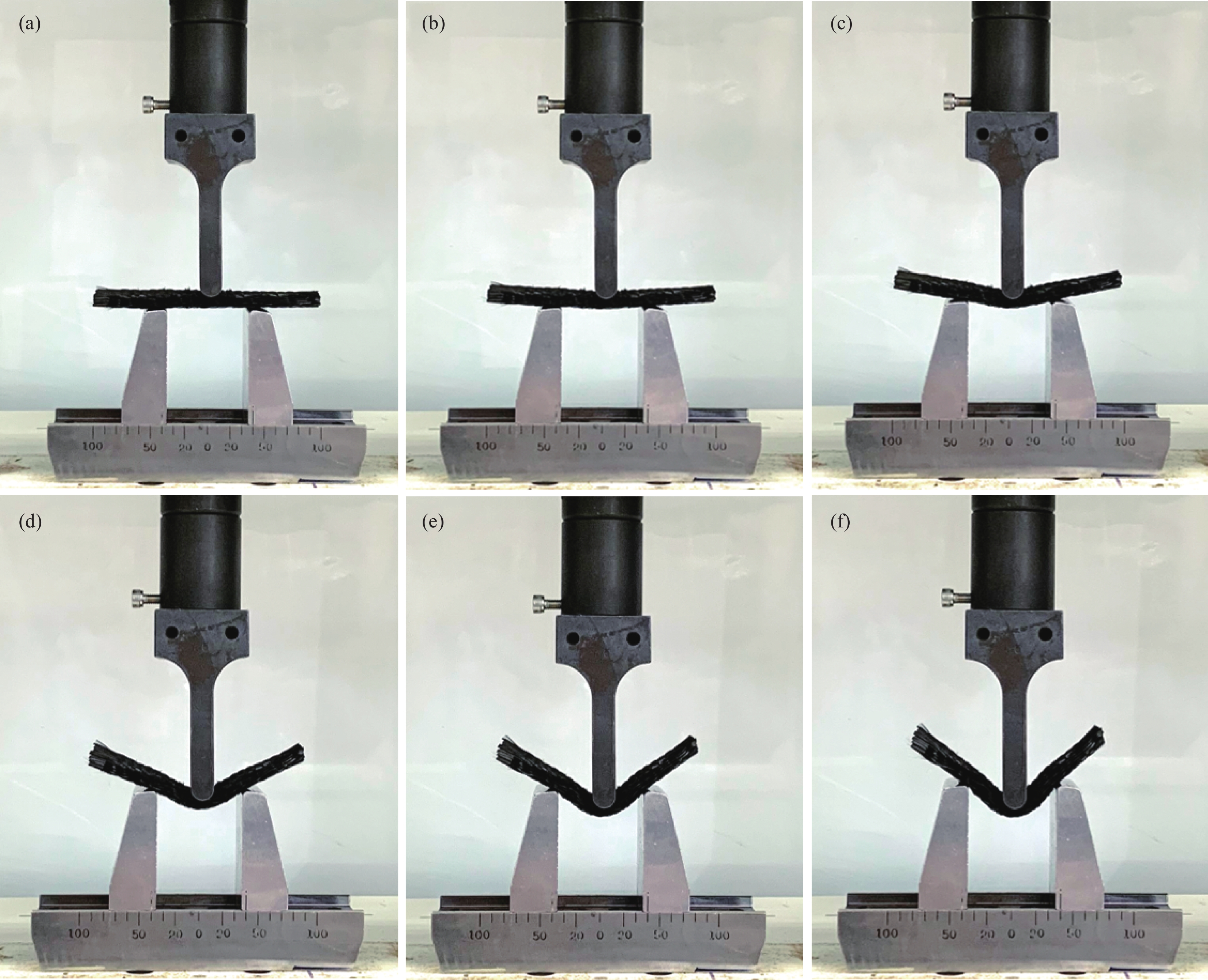
三点弯曲实验过程中,预制体样件的弯曲变形如图3所示。随着弯曲挠度的增大,试样两端逐渐翘起,变形后的预制体试样呈“V”字形。当弯曲挠度达到10 mm左右时,试样与支座之间开始发生显著滑移。三点弯曲载荷下预制体试样的变形曲率并不均匀,靠近压头的位置曲率较大,两端位置曲率很小,几乎呈平直状态。
![]() 图 3 预制体三点弯曲测试:(a) 0 mm;(b) 2 mm;(c) 4 mm;(d) 6 mm;(e) 8 mm;(f) 10 mmFigure 3. Three-point bending test of the preform: (a) 0 mm; (b) 2 mm; (c) 4 mm; (d) 6 mm; (e) 8 mm; (f) 10 mm
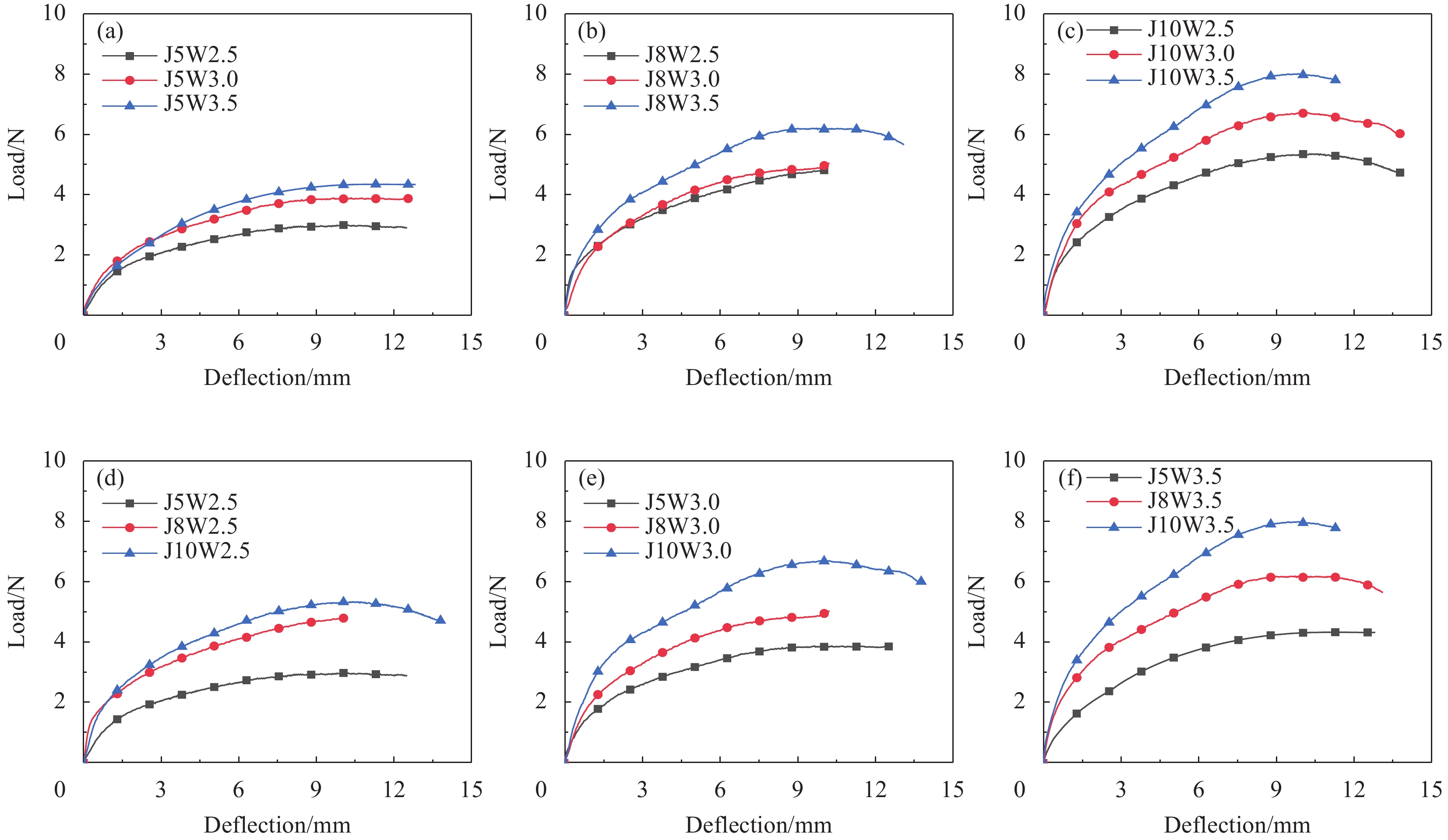
图 3 预制体三点弯曲测试:(a) 0 mm;(b) 2 mm;(c) 4 mm;(d) 6 mm;(e) 8 mm;(f) 10 mmFigure 3. Three-point bending test of the preform: (a) 0 mm; (b) 2 mm; (c) 4 mm; (d) 6 mm; (e) 8 mm; (f) 10 mm图4显示了不同结构参数的预制体弯曲载荷-挠度曲线。不同试样的载荷-挠度曲线变化趋势大致相同,曲线均表现出显著的非线性特征,当挠度达到10 mm左右时,弯曲载荷基本达到峰值,弯曲挠度继续增加时,弯曲载荷不再增加,随着试样与支座之间发生滑移,弯曲载荷逐渐下降,直到试样脱离支座。
![]() 图 4 3D机织预制体三点弯曲试样载荷-挠度曲线:((a)~(c)) 经纱密度5根/cm、8根/cm、10根/cm;((d)~(f)) 纬纱密度2.5根/cm、3.0根/cm、3.5根/cmFigure 4. Load-deflection curves of three-point bending samples of 3D woven preform: ((a)-(c)) Warp densities of 5 ends/cm, 8 ends/cm and 10 ends/cm; ((d)-(f)) Weft densities of 2.5 picks/cm, 3.0 picks/cm and 3.5 picks/cm
图 4 3D机织预制体三点弯曲试样载荷-挠度曲线:((a)~(c)) 经纱密度5根/cm、8根/cm、10根/cm;((d)~(f)) 纬纱密度2.5根/cm、3.0根/cm、3.5根/cmFigure 4. Load-deflection curves of three-point bending samples of 3D woven preform: ((a)-(c)) Warp densities of 5 ends/cm, 8 ends/cm and 10 ends/cm; ((d)-(f)) Weft densities of 2.5 picks/cm, 3.0 picks/cm and 3.5 picks/cm当试样经纱密度相同时,纬纱密度越大,弯曲载荷的峰值越大;同样地,当试样纬纱密度相同时,经纱密度越大,弯曲载荷的峰值也越大。这说明3D机织预制体的弯曲性能与试样内部的组织点密度(dw,单位体积内组织点的数量)密切相关,组织点密度越大,试样越不容易发生弯曲变形。
2.2 3D机织预制体临界弯曲能量
织物预制体是一种柔性材料,当弯曲挠度超过某一临界弯曲挠度值dc (dc约为10 mm)时,试样与三点弯曲支座开始发生滑移,随着弯曲挠度的继续增加,试样逐渐脱离支座。因此,本文认为试样弯曲挠度小于dc时为稳定弯曲状态。当弯曲挠度为dc时,载荷值为Fc、载荷累积做功为Ec (对应图5曲线下方的面积)。将Ec定义为试样的临界弯曲能量,表征其抗弯曲性能。
![]() 图 5 3D机织预制体三点弯曲试样临界弯曲能量Figure 5. Critical bending energy of three-point bending sample of 3D woven preformEi—Bending energy under a certain bending deflection; F—Bending load; Fc—Critical bending load value; Fi—Bending load value under a certain bending deflection; d—Bending deflection; dc—Critical bending deflection value; Δd—Unit bending deflection value
图 5 3D机织预制体三点弯曲试样临界弯曲能量Figure 5. Critical bending energy of three-point bending sample of 3D woven preformEi—Bending energy under a certain bending deflection; F—Bending load; Fc—Critical bending load value; Fi—Bending load value under a certain bending deflection; d—Bending deflection; dc—Critical bending deflection value; Δd—Unit bending deflection value将曲线覆盖区域分为n个宽Δd的狭长矩形,第i个矩形的高度为Fi,则临界弯曲能量Ec可由下式计算:
Ec=∑Ei=∑FiΔd (1) 预制体的弯曲性能与其组织点密度dw有关,dw由下式计算:
dw=dwarpdweftnwarpN (2) 其中:
dwarp 为经纱密度;dweft 为纬纱密度;nwarp 为经纱层数,N=4表示一根经纱上两个相邻组织点跨越的纬纱数量。不同预制体样件的组织点密度如表1中所示。图6给出了预制体临界弯曲能量Ec与组织点密度dw的关联关系。结果显示,Ec随着dw的增加而增大,二者大致呈线性关系。预制体组织点密度越大,纱线排布越紧密、彼此之间的相互约束力越强,因此弯曲变形时所需的临界弯曲能量越大。![]() 图 6 组织点密度对3D机织预制体临界弯曲能量的影响Figure 6. Effect of weaving point density on critical bending energy of 3D woven preformEc—Critical bending energy
图 6 组织点密度对3D机织预制体临界弯曲能量的影响Figure 6. Effect of weaving point density on critical bending energy of 3D woven preformEc—Critical bending energy2.3 3D机织预制体经纱屈曲度变化
碳纤维3D机织预制体发生宏观弯曲变形后,其内部微细观结构也发生了显著变化。本文对典型结构的预制体试样(J5W3.0)开展了变形前、后的Micro-CT扫描测试。弯曲变形前,预制体内部的纱线排布比较规则:纬纱沿厚度方向排布成列,各纬纱列基本呈竖直状态;经纱与纬纱相互交织,一根经纱将上下相邻的两层纬纱连锁起来,各层经纱的路径基本一致。
弯曲变形后,经纱的屈曲形态会发生显著变化。引入经纱屈曲度
Bwarp 来表征变形前后经纱屈曲形态的变化:Bwarp=Lwarp−LbaseLbase (3) 其中:
Lwarp 为经纱实际长度(图7实线长度);Lbase 为基准线长度(图7虚线长度)。弯曲变形前,Lbase 是纱线两端的直线间距。弯曲变形后,基准线随着试样变形为弧线,Lbase 为图7(b)所示的弧线长度,该弧线是连接上下两层纬纱各中心点的样条曲线。![]() 图 7 3D机织预制体经纱屈曲度的定义:(a) 变形前;(b) 变形后Figure 7. Definition of buckling degree of warp yarn of 3D woven preform: (a) Before deformation; (b) After deformationLbase—Baseline length
图 7 3D机织预制体经纱屈曲度的定义:(a) 变形前;(b) 变形后Figure 7. Definition of buckling degree of warp yarn of 3D woven preform: (a) Before deformation; (b) After deformationLbase—Baseline length预制体弯曲变形前、后,其内部各层经纱的路径分别如图8(a)和图8(b)所示,其中L1~L6表示第1层~第6层经纱。弯曲变形后,预制体样件表层经纱受压、底层经纱受拉,因此不同位置处的经纱屈曲度发生了变化。预制体样件在变形前、后的经纱屈曲度如图8(c)所示。未变形前各层经纱长度基本相同,屈曲度均为0.025。弯曲变形后,底层经纱(L1~L2)在拉伸载荷下伸直,屈曲度降低;中间层经纱(L3~L4)的屈曲度与变形前相比变化不大;表层经纱(L5~L6)在压缩载荷下屈曲度进一步提高。由底层至表层,经纱的屈曲度明显增大,L6经纱的屈曲度比L1经纱提高了98.3%。
![]() 图 8 3D机织预制体:(a) 变形前经纱路径;(b) 变形后经纱路径;(c) 变形前后经纱屈曲度对比Figure 8. 3D woven preform: (a) Warp yarn path before deformation; (b) Warp yarn path after deformation; (c) Comparison between buckling degree of warp yarns before and after deformationL—Layer
图 8 3D机织预制体:(a) 变形前经纱路径;(b) 变形后经纱路径;(c) 变形前后经纱屈曲度对比Figure 8. 3D woven preform: (a) Warp yarn path before deformation; (b) Warp yarn path after deformation; (c) Comparison between buckling degree of warp yarns before and after deformationL—Layer弯曲变形会引起表层经纱的局部屈曲现象,如图9所示。这些位置的经纱没有其他纱线的约束,处于自由状态,受到纵向压缩时容易产生横向膨胀,即“负泊松”效应。L1经纱的局部屈曲使试样表面产生褶皱。试样内部的经纱在弯曲变形时的屈曲度较低,而且与周围纱线相接触,处于受约束状态,一般不会产生屈曲现象。
![]() 图 9 3D机织预制体表面经纱的局部屈曲Figure 9. Local buckling of the surface warp yarn of 3D woven preform
图 9 3D机织预制体表面经纱的局部屈曲Figure 9. Local buckling of the surface warp yarn of 3D woven preform2.4 3D机织预制体纬纱列偏转角度
弯曲变形前,纬纱列的排布呈竖直状态,穿过纬纱列的直线与试样表面大致垂直。弯曲变形后,纬纱列的排布仍然保持为直线,但不再与试样表面垂直。可见,高厚度的碳纤维3D机织预制体的弯曲行为不符合Kirchhoff薄板弯曲理论,预制体弯曲过程中发生了层间剪切变形,即纬纱和经纱之间发生了层间滑移。为了量化分析预制体试样的层间剪切变形,本文基于Micro-CT扫描图像统计了8列纬纱(C1~C8)的偏转角度,如图10(a)所示。其中,织物表面路径是沿着试样上表面轮廓线进行设定的,在压头附近,试样与压头紧密贴合,此处的轮廓线曲率与压头曲率一致。纬纱列偏转角度为预制体初始法向和纬纱列方向之间的夹角。初始法向为经过表层纬纱形心且垂直于织物表面路径的直线(图10(a)点虚线);纬纱列方向为连接表层和底层纬纱形心的直线(图10(a)虚线)。统计结果如图10(b)所示:压头左右两侧纬纱列的偏转角度大致对称分布;靠近压头的纬纱列偏转角较小,远离压头的纬纱列偏转角较大;随着与压头距离的增大,纬纱列偏转角度表现出先增大后减小的趋势,最大偏转角度为26.85°。
![]() 图 10 3D机织预制体纬纱列偏转角:(a) 基于Micro-CT图像的测量;(b) 统计结果Figure 10. Weft row deflection angle of 3D woven preform: (a) Measurement based on Micro-CT image; (b) Statistical resultC—Column
图 10 3D机织预制体纬纱列偏转角:(a) 基于Micro-CT图像的测量;(b) 统计结果Figure 10. Weft row deflection angle of 3D woven preform: (a) Measurement based on Micro-CT image; (b) Statistical resultC—Column3. 结 论
研究了碳纤维3D机织预制体结构参数对其弯曲性能的影响,基于Micro-CT技术分析了弯曲变形前后预制体内部细观结构的变化,得出以下结论:
(1) 碳纤维3D机织预制体的弯曲载荷-挠度曲线表现出显著的非线性特征,经、纬密较大时,预制体结构紧密,不容易发生弯曲变形;
(2) 预制体样件在三点弯曲测试中挠度小于10 mm时为稳定弯曲变形,临界弯曲能量随着组织点密度的增加线性增大;
(3) 碳纤维3D机织预制体的弯曲变形由经纱屈曲度变化、局部压缩屈曲和经纬纱层间滑移等微细观变形构成;
(4) 预制体发生弯曲变形后,其内部的微细观变形并不均匀,不同位置的纤维结构差异较大,会导致最终复合材料力学性能的离散性。
-
![]()
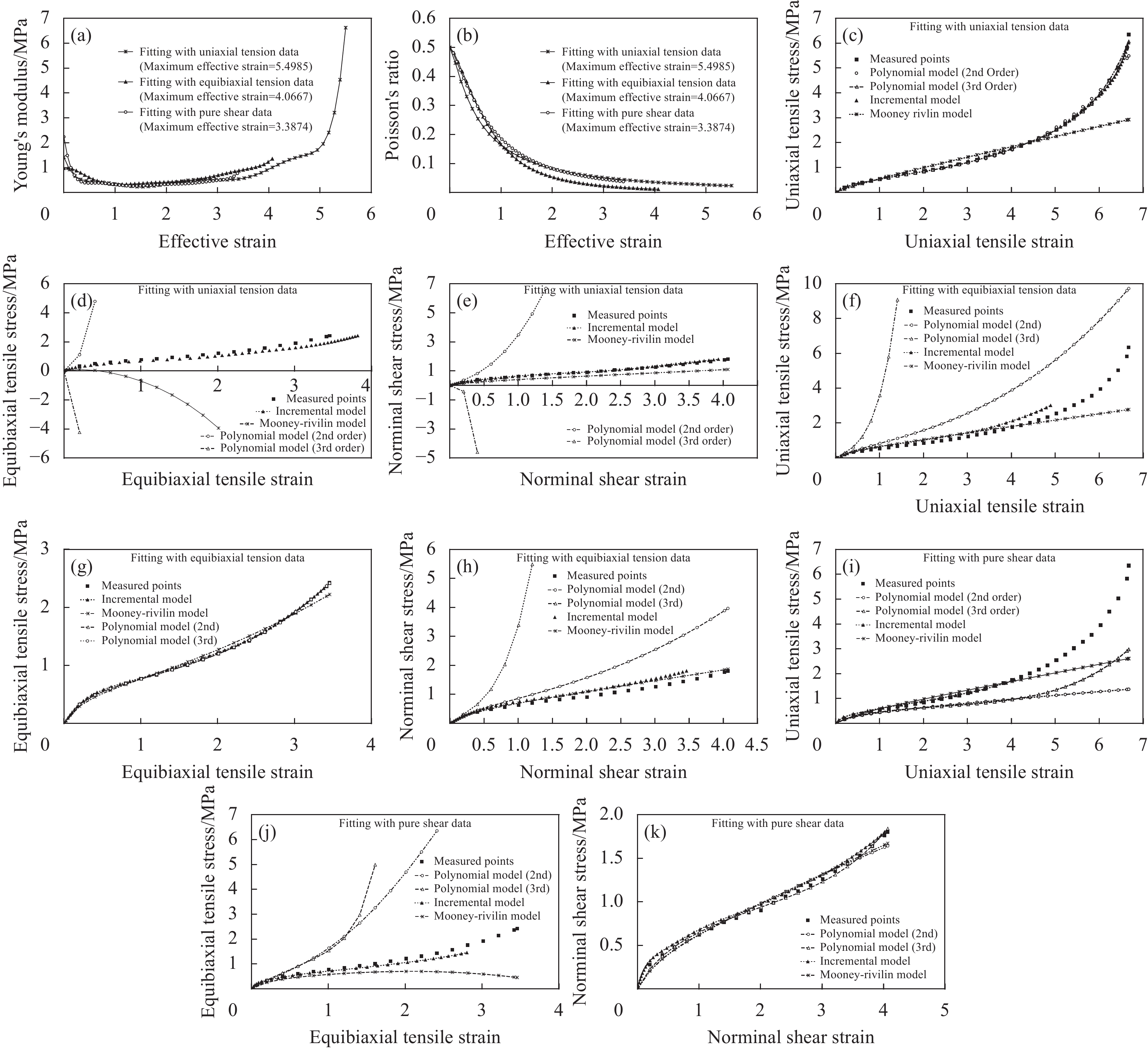
图 1 连续纤维 (a) 和短纤维复合材料 (b) 的代表性单元(RVE)(l/a≈1对应颗粒复合材料)
Figure 1. Representative unit (RVE) of a continuous fiber composite (a) and a short fiber composite (b) (l/a≈1 corresponds to a particle composite)
a—Fiber radius; b—Matrix radius; L—Half length of matrix; l—Half length of fiber; Vf—Fiber volume fraction; (r, q, z)—Cylindrical coordinates; (x1, x2, x3)—Rectandular coordinates; Ω1—A portion of RVE with fiber; Ω2—A portion of RVE without fiber
![]()
图 14 复合材料结构破坏和强度分析流程图
Figure 14. A flow chart to show failure analysis and strength predictions for any composite structure
![]()
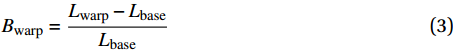
图 2 超弹性本构模型预报与Treloar的橡胶实验[73]对比:(a) 模量-名义应变(E-εe)曲线;(b) 泊松比-名义应变(ν-εe)曲线;((c)~(e)) 单轴拉伸实验拟合模型参数后预报的单轴拉伸、等值双轴拉伸、纯剪切直到破坏的曲线与实验对比;((f)~(h)) 等值双轴拉伸实验拟合模型参数后预报的单轴拉伸、等值双轴拉伸、纯剪切直到破坏的曲线与实验对比;((i)~(k)) 纯剪切实验拟合模型参数后预报的单轴拉伸、等值双轴拉伸、纯剪切直到破坏的曲线与实验对比
Figure 2. Hyperelastic theories verified through Treloar’s test data on a rubber[73]: (a) Modulus versus equivalent strain (E-εe) curves; (b) Poisson’s ratio versus equivalent strain (ν-εe) curves; ((c)-(e)) Comparisons between the measured and predicted uniaxial tension, equalbiaxial tension and pure shear curves by different models fitted with uniaxial tension test data; ((f)-(h)) Comparisons between the measured and predicted uniaxial tension, equalbiaxial tension, pure shear curves by different models fitted with equalbiaxial tension test data; ((i)-(k)) Comparisons between the measured and predicted uniaxial tension, equalbiaxial tension, pure shear curves by different models fitted with pure shear test data
![]()
图 3 对应不同标度应力的复合材料性能示意图
Figure 3. Schematic disgram to show composite properties at different scales of stresses
σ—Stress; ε—Strain; E—Elastic modulus; ET—Hardening modulus
![]()
图 4 RVE界面开裂后纤维和基体之间相对滑移示意图:(a) 纵截面;(b) 横界面
Figure 4. Schematic of relative slippage displacement between debonded fiber and matrix interfaces in a RVE: (a) Longitudinal cross-section; (b) Transverse cross-section
D, D', F—Label of the point; σ12 0—In-plane shear stress applied on the RVE; d—Relatic slippage displacement between debonded fiber and matrix interfaces; Ψ—Half debonding angle
![]()
图 5 机织纤维 (a)、针织纤维 (b)、短纤维增强复合材料 (c) 重复单胞示意图
Figure 5. A repeating unit cell for woven fabric composite (a), knitted fabric composite (b), short fiber reinforced composite (c)
![]()
![]()
图 7 层合板的双悬臂梁(DCB) (a) 和端部开口弯曲(ENF) (b) 实验和有限元模拟
Figure 7. Experimental and finite element approaches on double cantilever beam (DCB) (a) and end-notched flexure (ENF) (b) samples
H—Thickness of the sample; PI, PII—Peak load of DCB, ENF ; δI, δII—Corresponding displacement; a0—Length of an initial crack
![]()
图 8 (a) 轴向拉伸引起的纤维撕裂破坏;(b) 轴向压缩引起的纤维偏折破坏[91];(c) 轴向加载在纤维偏折坐标系的应力分量
Figure 8. (a) Fiber splitting failure under a longitudinal tension; (b) Fiber kinking failure under a longitudinal compression[91]; (c) A longitudinal load induced stress components in the misaligned coordinate system
σL—Axial stress; τ—Shear stress; θf,00—Initial fiber misalignment angle; σT—Transverse stress; xI1, xI2—Misaligned coordinate system
![]()
图 9 (a) 基体斜截面上拉伸正应力对应的破坏应力状态;(b) 拉伸破坏面包络线由基体拉伸和剪切强度构建的抛物线近似
Figure 9. (a) Failure stress state of an inclined cross-section with a positive outward normal stress; (b) Tensile failure envelope approaximated by a parabola determined from matrix’s tensile and shear strengths
![]()
图 10 单向复合材料受横向压缩破坏图
Figure 10. Failure disgram of a unidirectional composite under a transverse compression
x2—Load direction; x3—Fiber direction
![]()
图 11 基体压缩引起的复合材料破坏示意图
Figure 11. Schematic of a matrix compression induced composite failure
{σ11, σ22,...}—Stresses on a unidirectional composite composite; {σn, τnt, τns}—Normal and two shear stresses of the composite on an inclined cross-section; {τmnt, τmn, τmns}—Normal and two shear stresses of the matrix on the inclined cross-section
![]()
图 12 复合材料弱奇异和应力集中截面邻域示意图(t为主层厚)
Figure 12. Schematic neibourhoods of weak singularity and stress concentration points in a composite (t is the thickness of a primary layer)
![]()
图 13 任意纤维(编织纤维结构为例)复合材料结构分析示意图
Figure 13. Schematic diagram to shown structural analysis for any fibrous composite structure (Using braided fabric composite as an examble)
表 1 复合材料破坏分类
Table 1 Classification for composite failures
Mode Characteristics Fatal failure Fiber tensile failure in a primary layer Fiber compressive failure in a primary layer Fiber splitting or kinking failure in a primary layer Non-fatal failure Matrix tensile failure in a primary layer Matrix compressive failure in a primary layer Damage type failure Interface crack between fiber and matrix Delamination between adjacent primary layers Non-fatal failure in a laminated composite Strength type failure There is a fatal failure A critical strain is attained after a non-fatal failure Ultimate failure of composite structure A strength type failure occurs outside neighborhoods of stress singularity (constrained boundary, loading point, etc.) and week singularity (hole edge, free edge, tapered laminate, etc.)  下载: 导出CSV
表 2 复合材料结构破坏与强度分析所需材料性能数据
Table 2 Material property parameters needed for failure and strength analysis of a composite structure
Property Source Remark Fiber elastic constants Material data sheet/fiber supplier/tests on UD Each fiber must provide 5 elastic constants (for transversely isotropic). Can be retrieved from Eqs. (12). Fiber tensile & compressive strengths Tests on UD/fiber supplier/material data sheet Each fiber must provide 2 strengths. Can be retrieved from Eqs. (55.1) and (55.2). Matrix elastic constants Tests on casting samples of matrix/matrix supplier Each matrix must provide its Young’s modulus and Poisson’s ratio Matrix tensile & shear strengths Tests on casting samples of matrix Each matrix must provide its measured tensile and shear strengths, with shear better obtained on Iosipescu method Matrix compressive strength Transverse compressive strength of UD/test on matrix/matrix supplier Each matrix must provide its compressive strength, best retrieved from Eq. (55.3) with Kc22 determined by Eqs. (56)[50,97] Matrix tensile curve Test on casting sample of matrix Define matrix tensile yield strength and hardening moduli, as long as the piece linear segments are near to the curve Matrix compress. curve Test on casting sample of matrix Define matrix compressive yield strength and hardening moduli, as long as piece linear segments near to the curve UD transverse tensile strength Test on UD Each composite system must provide its transverse tensile strength to understand interface bonding status Critical displacements
δI and δIIDCB and ENF tests Preferably each pair of two different materials used in the structure should provide the DCB and ENF test data Fiber initial misalignment θf,0c=1.50 Empirical data Neighborhood ranges n1=4, n2=24 Empirical data Note: UD—Unidirectional composite.
下载: 导出CSV
-
[1] WANG Y C, HUANG Z M. Analytical micromechanics models for elastoplastic behavior of long fibrous compo-sites: A critical review and comparative study[J]. Materials,2018,11(10):1919. DOI: 10.3390/ma11101919
[2] HAHN H T, TSAI S W. Nonlinear elastic behaviour of unidirectional composite laminates[J]. Journal of Compo-site Materials,1973,7:102-110. DOI: 10.1177/002199837300700108
[3] SUN C T, CHEN J L. A micromechanical model for plastic behavior of fibrous composites[J]. Composites Science and Technology,1991,40(2):115-129. DOI: 10.1016/0266-3538(91)90092-4
[4] MORI T, TANAKA K. Average stress in matrix and average elastic energy of materials with misfitting inclusions[J]. Acta Metallurgica,1973,21:571-574. DOI: 10.1016/0001-6160(73)90064-3
[5] HILL R. A self-consistent mechanics of composite materials[J]. Journal of the Mechanics and Physics of Solids,1965,13:213-222. DOI: 10.1016/0022-5096(65)90010-4
[6] HASHIN Z, ROSEN B W. The elastic moduli of fiber-reinforced materials[J]. Journal of Applied Mechanics,1964,31:223-232. DOI: 10.1115/1.3629590
[7] CHRISTENSEN R M, LO K H. Solutions for effective shear properties in three phase sphere and cylinder models[J]. Journal of the Mechanics and Physics of Solids,1979,27:315-330. DOI: 10.1016/0022-5096(79)90032-2
[8] HORI M, NEMAT-NASSER S. Double-inclusion model and overall moduli of multi-phase composites[J]. Journal of Engineering Materials and Technology,1994,116:305-309. DOI: 10.1115/1.2904292
[9] HU G K, WENG G J. The connections between the double inclusion model and the Ponte Castaneda-Wills, Mori-Tanaka, and Kuster-Toksoz models[J]. Mechanics of Materials,2000,32:495-503. DOI: 10.1016/S0167-6636(00)00015-6
[10] ABOUTAJEDDINE A, NEALE K W. The double inclusion model a new formulation and new estimates[J]. Mecha-nics of Materials,2005,37:331-341. DOI: 10.1016/j.mechmat.2003.08.016
[11] WANG Y C, HUANG Z M. A new approach to a bridging tensor[J]. Polymer Composites,2015,36:1417-1431. DOI: 10.1002/pc.23048
[12] WANG Y C, HUANG Z M. Bridging tensor with an imperfect interface[J]. European Journal of Mechanics-A/Solids,2016,56:73-91. DOI: 10.1016/j.euromechsol.2015.10.006
[13] ABOUDI J. Mechanics of composite materials: A unified micromechanical approach[M]. Amsterdam: Elsevier, 2013.
[14] GHORBANI M M, ACHUTHAN A, BEDNARCYK B A, et al. A multi-scale computational model using generalized method of cells (GMC) homogenization for multi-phase single crystal metals[J]. Computational Materials Science,2015,96:44-55. DOI: 10.1016/j.commatsci.2014.08.045
[15] CAVALCANTE M A A, PINDERA M J. Generalized finite-volume theory for elastic stress analysis in solid mechanics—Part I: Framework[J]. Journal of Applied Mechanics,2012,79:051006. DOI: 10.1115/1.4006805
[16] CAVALCANTE M A A, PINDERA M J. Generalized finite-volume theory for elastic stress analysis in solid mechanics—Part II: Results[J]. Journal of Applied Mechanics,2012,79:051007. DOI: 10.1115/1.4006806
[17] DEMIRDŽIĆ I. A fourth-order finite volume method for structural analysis[J]. Applied Mathematical Modelling,2016,40:3104-3114. DOI: 10.1016/j.apm.2015.09.098
[18] DOGHRI I, OUAAR A. Homogenization of two-phase elasto-plastic composite materials and structures—Study of tangent operators, cyclic plasticity and numerical algorithms[J]. International Journal of Solids & Structures,2003,40:1681-1712. DOI: 10.1016/S0020-7683(03)00013-1
[19] REKIK A, BORNERT M, AUSLENDER F. A critical evaluation of local field statistics predicted by various linearization schemes in nonlinear mean-field homogenization[J]. Mechanics of Materials,2012,54:1-17. DOI: 10.1016/j.mechmat.2012.05.011
[20] KANAUN S. An efficient homogenization method for composite materials with elasto-plastic components[J]. International Journal of Engineering Science,2012,57:36-49. DOI: 10.1016/j.ijengsci.2012.04.005
[21] GAVAZZI A C, LAGOUDAS D C. On the numerical evaluation of Eshelby's tensor and its application to elastoplastic fibrous composites[J]. Computational Mechanics,1990,7(1):13-19. DOI: 10.1007/BF00370053
[22] HUANG Z M. A unified micromechanical model for the mechanical properties of two constituent composite materials, Part I: Elastic behavior[J]. Journal of Thermoplastic Composite Materials,2000,13(4):252-271. DOI: 10.1177/089270570001300401
[23] HUANG Z M. A unified micromechanical model for the mechanical properties of two constituent composite materials, Part II: Plastic behavior[J]. Journal of Thermoplastic Composite Materials,2000,13(5):344-362. DOI: 10.1106/74AD-GXYK-6NQH-L2AV
[24] HUANG Z M. Micromechanical prediction of ultimate strength of transversely isotropic fibrous composites[J]. International Journal of Solids & Structures,2001,38(22-23):4147-4172. DOI: 10.1016/S0020-7683(00)00268-7
[25] HUANG Z M. Simulation of the mechanical properties of fibrous composites by the bridging micromechanics model[J]. Composites Part A: Applied Science and Manufacturing,2001,32(2):143-172. DOI: 10.1016/S1359-835X(00)00142-1
[26] HUANG Z M, ZHOU Y X. Strength of fibrous composites-Advanced topics in science & technology in China[M]. Hangzhou & Heidelberg: Zhejiang University Press & Springer, 2011.
[27] 黄争鸣. 复合材料破坏与强度[M]. 北京: 科学出版社, 2018. HUANG Z M. Failures and strengths of composite materials[M]. Beijing: Science Press, 2018(in Chinese).
[28] HUANG Z M, ZHANG C C, XUE Y D. Stiffness prediction of short fiber reinforced composites[J]. International Journal of Mechanical Sciences,2019,161-162:105068. DOI: 10.1016/j.ijmecsci.2019.105068
[29] HUANG H B, HUANG Z M. Micromechanical prediction of elastic-plastic behavior of a short fiber or particle reinforced composite[J]. Composites Part A: Applied Science and Manufacturing,2020,134:105889. DOI: 10.1016/j.compositesa.2020.105889
[30] RYAN S, WICKLEIN M, MOURITZ A, et al. Theoretical prediction of dynamic composite material properties for hypervelocity impact simulations[J]. International Journal of Impact Engineering,2009,36:899-912. DOI: 10.1016/j.ijimpeng.2008.12.012
[31] SHAW A, SRIRAMULA S, GOSLING P D, et al. A critical reliability evaluation of fibre reinforced composite materials based on probabilistic micro and macro-mechanical analysis[J]. Composites Part B: Engineering,2010,41:446-453. DOI: 10.1016/j.compositesb.2010.05.005
[32] YOUNES R, HALLAL A, FARDOUN F, et al. Comparative review study on elastic properties modeling for unidirectional composite materials[M]//Composites and Their Properties. Chapter 17, 2012: 391-408.
[33] GHASEMI A R, MOHAMMADI M M, MOHANDES M. The role of carbon nanofibers on thermo mechanical properties of polymer matrix composites and their effect on reduction of residual stresses[J]. Composites Part B: Engi-neering,2015,77:519-527. DOI: 10.1016/j.compositesb.2015.03.065
[34] VIGNOLI L L, SAVI M A, PACHECO P M C L, et al. Comparative analysis of micromechanical models for the elastic composite laminae[J]. Composites Part B: Engineering,2019,174:106961. DOI: 10.1016/j.compositesb.2019.106961
[35] HUANG Z M. On micromechanics approach to stiffness and strength of unidirectional composites[J]. Journal of Reinforced Plastics and Composites,2019,38(4):167-196.
[36] GUEDES R M. Validation of trace-based approach to elastic properties of multidirectional glass fibre reinforced composites[J]. Composite Structures,2021,257:113170. DOI: 10.1016/j.compstruct.2020.113170
[37] HUANG Z M, LIU L. Predicting strength of fibrous laminates under triaxial loads only upon independently measured constituent properties[J]. International Journal of Mechanical Sciences,2014,79:105-129. DOI: 10.1016/j.ijmecsci.2013.08.010
[38] HUANG Z M, XIN L M. In situ strengths of matrix in a composite[J]. Acta Mechanica Sinica,2017,33(1):120-131. DOI: 10.1007/s10409-016-0611-1
[39] LIU L, HUANG Z M. Stress concentration factor in matrix of a composite reinforced with transversely isotropic fibers[J]. Journal of Composite Materials,2014,48(1):81-98. DOI: 10.1177/0021998312469237
[40] HUANG Z M, LIU L. Assessment of composite failure and ultimate strength without experiment on composite[J]. Acta Mechanica Sinica,2014,30(4):569-588. DOI: 10.1007/s10409-014-0040-y
[41] HUANG Z M, XIN L M. Stress concentration factor in matrix of a composite subjected to transverse compression[J]. International Journal of Applied Mechanics,2016,8(3):1650034. DOI: 10.1142/S1758825116500344
[42] ZHOU Y, HUANG Z M, LIU L. Prediction of interfacial debonding in fiber-reinforced composite laminates[J]. Polymer Composites,2019,40(5):1828-1841. DOI: 10.1002/pc.24943
[43] HUANG Z M. Micromechanical failure analysis of unidirectional composites[C]//Failure Analysis, IntechOpen, 2019.
[44] HUANG Z M, GUO W J, HUANG H B, et al. Tensile strength prediction of short fiber reinforced composites[J]. Materials,2021,14(11):2708. DOI: 10.3390/ma14112708
[45] 郭威静, 黄争鸣. 短纤维复合材料的压缩强度[J]. 固体力学学报, 2022, 43(1):1-15. GUO W J, HUANG Z M. Compressive strength of a shrt fiber composite[J]. Chinese Journal of Solid Mechanics,2022,43(1):1-15(in Chinese).
[46] ZHOU Y, HUANG Z M. Prediction of in-plane shear pro-perties of a composite with debonded interface[J]. Applied Composite Materials, 2022, 29: 901-935.
[47] YU M H. Advances in strength theories for materials under complex stress state in the 20th century[J]. Advances in Mechanics,2002,55(3):169-218. DOI: 10.1115/1.1472455
[48] ORIFICI A C, HERSZBERG I, THOMSON R S. Review of methodologies for composite material modelling incorporating failure[J]. Composite Structures,2008,86(1-3):194-210. DOI: 10.1016/j.compstruct.2008.03.007
[49] TALREJA R. Assessment of the fundamentals of failure theories for composite materials[J]. Composites Science & Technology,2014,105:190-201. DOI: 10.1016/j.compscitech.2014.10.014
[50] HUANG Z M, WANG L S, JIANG F, et al. Detection on matrix induced composite failures[J]. Composites Science & Technology,2021,205:108670. DOI: 10.1016/j.compscitech.2021.108670
[51] WANG L S, HUANG Z M. On strength prediction of laminated composites[J]. Composites Science & Technology,2022,219:109206. DOI: 10.1016/j.compscitech.2021.109206
[52] BAK B L V, SARRADO C, TURON A, et al. Delamination under fatigue loads in composite laminates: A review on the observed phenomenology and computational methods[J]. Applied Mechanics Reviews,2014,66:060803. DOI: 10.1115/1.4027647
[53] TABIEI A, ZHANG W. Composite laminate delamination simulation and experiment: A review of recent development[J]. Applied Mechanics Reviews,2018,70:030801. DOI: 10.1115/1.4040448
[54] BARENBLATT G I. The mathematical theory of equilibrium cracks in brittle fracture[J]. Advances in Applied Mechanics,1962,7(1):55-129.
[55] DUGDALE D S. Yielding of steel sheets containing slits[J]. Journal of the Mechanics and Physics of Solids,1960,8(2):100-104. DOI: 10.1016/0022-5096(60)90013-2
[56] RYBICKI E F, KANNINEN M F. A finite element calculation of stress intensity factors by a modified crack closure integral[J]. Engineering Fracture Mechanics,1977,9(4):931-938. DOI: 10.1016/0013-7944(77)90013-3
[57] KRUEGER R. Virtual crack closure technique: history, approach, and applications[J]. Applied Mechanics Reviews,2004,57(2):109-143. DOI: 10.1115/1.1595677
[58] BELYTSCHKO T, BLACK T. Elastic crack growth in finite elements with minimal remeshing[J]. International Journal for Numerical Methods in Engineering,1999,45(5):601-620. DOI: 10.1002/(SICI)1097-0207(19990620)45:5<601::AID-NME598>3.0.CO;2-S
[59] MOTAMEDI D, MILANI A S. 3D nonlinear XFEM simulation of delamination in unidirectional composite laminates: A sensitivity analysis of modeling parameters[J]. Open Journal of Composite Materials ,2013,3(4):113-126.
[60] HUANG Z M, LI P. Prediction of laminate delamination with no iteration[J]. Engineering Fracture Mechanics,2020,238:107248. DOI: 10.1016/j.engfracmech.2020.107248
[61] ZHOU J C, HUANG Z M, XU W. Prediction of laminate delamination from strength failure of interlaminar matrix-layer[J/OL]. Journal of Reinforced Plastics and Compo-sites, 2022-05-01[2022-07-21].
[62] ZHOU J C, HUANG Z M. Predicting delamination of hybrid laminate via stress modification on interlaminar matrix layer[J]. Engineering Fracture Mechanics,2022,264:108333. DOI: 10.1016/j.engfracmech.2022.108333
[63] ABAQUS. Theory manual[M]. Version 5.5. Hibbitt, Karlsson & Sorensen, Inc., 1995.
[64] TRELOAR L R G. The physics of rubber elasticity[M]. 3rd ed. Oxford: larendon Press, 1975.
[65] OGDEN R W. Non-linear elastic deformations[M]. New York: Wiley, 1984.
[66] HUANG Z M. A unified micromechanical model for the mechanical properties of two constituent composite materials, Part IV: Rubber-elastic behavior[J]. Journal of Thermoplastic Composite Materials,2000,13(2):119-139. DOI: 10.1177/089270570001300203
[67] HUANG Z M, RAMAKRISHNA S, TAY A A O. Modelling of stress-strain behavior of a knitted fabric reinforced elastomer composite[J]. Composites Science & Technology,2000,60(5):671-691. DOI: 10.1016/S0266-3538(99)00164-5
[68] SEGURADO J, LLORCA J. A numerical approximation to the elastic properties of sphere-reinforced composites[J]. Journal of the Mechanics & Physics of Solids,2002,50:2107-2121. DOI: 10.1016/S0022-5096(02)00021-2
[69] JIANG Z, LIU X, LI G, et al. A new analytical model for three-dimensional elastic stress field distribution in short fibre composite[J]. Materials Science and Engineering: A,2004,366(2):381-396. DOI: 10.1016/j.msea.2003.09.055
[70] GADALA R W. Numerical solutions of nonlinear problems of continua—II. Survey of incompressibility constraints and software aspects[J]. Computers & Structures,1986,22:841-855. DOI: 10.1016/0045-7949(86)90273-7
[71] SUSSMAN T, BATHE K J. A finite element formulation for nonlinear incompressible elastic and inelastic analysis[J]. Computers & Structures,1987,26:357-409. DOI: 10.1016/0045-7949(87)90265-3
[72] PENG S H, CHANG W J. A compressible approach in finite element analysis of rubber-elastic materials[J]. Computers & Structures,1997,62:573-593. DOI: 10.1016/S0045-7949(96)00195-2
[73] TRELOAR L R G. Stress-strain data for vulcanised rubber under various types of deformation[J]. Transactions of the Faraday Society,1944,40:59-70. DOI: 10.1039/tf9444000059
[74] SODEN P D, HINTON M J, KADDOUR A S. Lamina properties, lay-up configurations and loading conditions for a range of fibre-reinforced composite laminates[J]. Composites Science and Technology,1998,58(7):1011-1022. DOI: 10.1016/S0266-3538(98)00078-5
[75] ESHELBY J D. The determination of the elastic field of an ellipsoidal inclusion and related Problems[J]. Proceedings of the Royal Society of London A,1957,A240:367-396.
[76] CHEN T, DVORAK G J, BENVENISTE Y. Stress fields in composites reinforced by coated cylindrically orthotropic fibers[J]. Mechmater Mechanics of Materials,1990,9:17-32. DOI: 10.1016/0167-6636(90)90027-D
[77] ZHOU Y, HUANG Z M. Shear deformation of a composite until failure with a debonded interface[J]. Composite Structures,2020,254:112797. DOI: 10.1016/j.compstruct.2020.112797
[78] HUANG Z M, RAMAKRISHNA S. Micromechanical modelling approaches for the stiffness and strength of knitted fabric composites: A review & comparative study[J]. Composites Part A: Applied Science & Manufacturing,2000,31(5):479-501. DOI: 10.1016/S1359-835X(99)00083-4
[79] HUANG Z M. Modeling and characterization of bending strength of braided fabric reinforced laminates[J]. Jour-nal of Composite Materials,2002,36(22):2537-2566. DOI: 10.1177/002199802761405286
[80] HUANG Z M. Progressive flexural failure analysis of laminated composites with knitted fabric reinforcement[J]. Mechanics of Materials,2004,36(3):239-260. DOI: 10.1016/S0167-6636(03)00011-5
[81] HOBBIEBRUNKEN T, HOJO M, ADACHI T, et al. Evaluation of interfacial strength in CF/epoxies using FEM and in-situ experiments[J]. Composites Part A: Applied Science & Manufacturing,2006,37(12):2248-2256. DOI: 10.1016/j.compositesa.2005.12.021
[82] MORTELL D J, TANNER D A, MCCARTHY C T. In-situ SEM study of transverse cracking and delamination in laminated composite materials[J]. Composites Science & Technology,2014,105:118-126. DOI: 10.1016/j.compscitech.2014.10.012
[83] KOYANAGI J, OGIHARA S, NAKATANI H, et al. Mechanical properties of fiber/matrix interface in polymer matrix composites[J]. Advanced Composite Materials,2014,23(5-6):551-570. DOI: 10.1080/09243046.2014.915125
[84] PUPPO H, EVENSEN H A. Interlaminar shear in laminated composites under generalized plane stress[J]. Jour-nal of Composite Materials,1970,4:204-220. DOI: 10.1177/002199837000400206
[85] PETROSSIAN Z, WISNOM M R. Prediction of delamination initiation and growth from discontinuous plies using interface elements[J]. Composites Part A: Applied Science & Manufacturing,1998,29:503-515. DOI: 10.1016/S1359-835X(97)00134-6
[86] CHERNIAEV A, TELICHEV I. Meso-scale modeling of hypervelocity impact damage in composite laminates[J]. Composites Part B: Engineering,2015,74:95-103. DOI: 10.1016/j.compositesb.2015.01.010
[87] FLETCHER T A, KIM T, DODWELL T J, et al. Resin treatment of free edges to aid certification of through thickness laminate strength[J]. Composite Structures,2016,146:26-33. DOI: 10.1016/j.compstruct.2016.02.074
[88] SAITO H, TAKEUCHI H, KIMPARA I. Experimental evaluation of the damage growth restraining in 90 layer of thin-ply CFRP cross-ply laminates[J]. Advanced Composite Materials,2012,21(1):57-66. DOI: 10.1163/156855112X629522
[89] PINHO S T, DARVIZEH R, ROBINSON P, et al. Material and structural response of polymer-matrix fibre-reinforced composites[J]. Journal of Composite Materials,2012,46(19-20):2313-2341. DOI: 10.1177/0021998312454478
[90] ZHOU Y X, HUANG Z M. A bridging model prediction of the ultimate strength of composite laminates subjected to triaxial loads[J]. Journal of Composite Materials,2012,46(19-20):2343-2378. DOI: 10.1177/0021998312449491
[91] SUN Q, GUO H, ZHOU G, et al. Experimental and computational analysis of failure mechanisms in unidirectional carbon fiber reinforced polymer laminates under longitudinal compression loading[J]. Composite Structures,2018,203:335-348. DOI: 10.1016/j.compstruct.2018.06.028
[92] ZHOU Y, HUANG Z M. Failure of fiber-reinforced composite laminates under longitudinal compression[J]. Journal of Composite Materials,2019,53(24):3395-3411. DOI: 10.1177/0021998319839217
[93] ZHOU Y, HUANG Z M, WANG J X. Splitting failure of a composite under longitudinal tension[J]. Polymer Composites, 2023, 44: 1116-1134.
[94] YURGARTIS S. Measurement of small angle fiber misalignments in continuous fiber composites[J]. Compo-sites Science & Technology,1987,30(4):279-293. DOI: 10.1016/0266-3538(87)90016-9
[95] HUANG Z M. Constitutive relation, deformation, failure and strength of composites reinforced with continuous/short fibers or particles[J]. Composite Structures,2021,262:113279. DOI: 10.1016/j.compstruct.2020.113279
[96] PUCK A, SHURMANN H. Failure analysis of FRP laminates by means of physically based phenomenological models[J]. Composites Science & Technology,1998,58(7):1045-1067. DOI: 10.1016/S0266-3538(96)00140-6
[97] PINHO S T, DAVILA C G, CAMNAHO P P, et al. Failure models and criteria for FRP under in-plane or three-dimensional stress states including shear non-linearity[R]. NASA/TM-2005-213530, 2005.
[98] PUCK A, SCHÜRMANN H. Failure analysis of FRP laminates by means of physically based phenomenological models[J]. Composites Science & Technology,2002,62(12-13):1633-1662. DOI: 10.1016/S0266-3538(01)00208-1
[99] PINHO S T, IANNUCCI L, ROBINSON P. Physically-based failure models and criteria for laminated fibre-reinforced composites with emphasis on fibre kinking: Part I: Development[J]. Composites Part A: Applied Science & Manufacturing,2006,37(1):63-73. DOI: 10.1016/j.compositesa.2005.04.016
[100] GARNICH M R, AKULA V M K. Review of degradation models for progressive failure analysis of fiber reinforced polymer composites[J]. Applied Mechanics Reviews,2009,62(1):010801. DOI: 10.1115/1.3013822
[101] GU J J, HUANG Z M. Assessing delamination initiation of angle-ply laminates from fiber and matrix properties[J]. Journal of Thermoplastic Composite Materials,2019,32(12):1601-1621. DOI: 10.1177/0892705718799840
[102] MA Q, HUANG Z M. Failure analysis of laminated structure containing hole through FE approach[J]. Composite Structures, 2023, 306: 116558.
[103] HUANG Z M. Micromechanical life prediction for composite laminates[J]. Mechanics of Materials,2001,33(4):185-199. DOI: 10.1016/S0167-6636(00)00056-9
[104] HUANG Z M. Micromechanical modeling of fatigue strength of unidirectional fibrous composites[J]. International Journal of Fatigue,2002,24(6):659-670. DOI: 10.1016/S0142-1123(01)00185-2
[105] HUANG Z M. Cyclic response of metal matrix composite laminates subjected to thermo- mechanical fatigue loads[J]. International Journal of Fatigue,2002,24(2-4):463-475. DOI: 10.1016/S0142-1123(01)00102-5
[106] HUANG Z M. Fatigue life prediction of a woven fabric composite subjected to biaxial cyclic loads[J]. Compo-sites Part A: Applied Science and Manufacturing,2002,33(2):253-266. DOI: 10.1016/S1359-835X(01)00091-4
[107] HUANG Z M, RAMAKRISHNA S, THWE A A. Modeling and characterization of fatigue strength of laminated composites with knitted fabric reinforcement[J]. Journal of Composite Materials,2002,36(15):1781-1801. DOI: 10.1177/0021998302036015168
[108] REKTORYS K. Variational methods in mathematics, science, and engineering[M]. Amsterdam: Springer, 1977.
-
期刊类型引用(2)
1. 朱琬清,谢军波,吴兰芳,陈利,杨林,刘静妍. 3D机织预制体准纤维尺度建模方法. 复合材料学报. 2024(03): 1528-1538 .  本站查看
本站查看
2. 蔣永亮,马文锁,马振宇,许泳豪,朱梦蝶. 低捻纱三维角联锁机织预制体的不稳定结构变形模型. 棉纺织技术. 2024(12): 38-44 . 百度学术
其他类型引用(1)
-


计量
- 文章访问数: 2476
- HTML全文浏览量: 750
- PDF下载量: 478
- 被引次数: 3
