

Effect of fit conditions on mechanical properties of C/SiC online riveting unit
-
摘要: 针对化学气相沉积(CVI)工艺2D C/SiC材料制备热结构中大量采用的在线铆钉连接形式及地面试验中表现出的特点,研究了铆钉与平板开孔之间采用间隙或过盈配合不同形式对力学性能的影响。制备了典型含铆钉单元试件并进行了细观形貌观测,通过铆钉顶出试验得到了不同配合条件下顶出静强度及疲劳规律;通过不同配合条件下含铆钉试件与开孔试件的拉伸静强度试验,获得了C/SiC在线铆接导致的面内连接强度性能下降的规律;描述了纤维束变形和材料局部区域破坏的特点,并依据形貌观测开展了数值计算验证。在此基础上,针对C/SiC过盈配合铆接形式提出了考虑孔边应力集中影响的改进点应力失效准则。结果表明:过盈配合可以改善铆钉与平板之间的连接可靠性,显著提高铆钉顶出静强度和疲劳强度,但过盈配合铆接的工艺过程使得孔边局部碳布纤维产生挤压偏折变形并导致了孔边预应力。Abstract: According to the on-line rivet connection forms widely used in chemical vapor infiltration (CVI) process 2D-C/SiC thermal structures and characteristics shown in ground tests, the effects of different forms of clearance or interference fit between rivets and flat openings on mechanical properties were studied. A typical test piece with rivets was prepared and the microscopic morphology was observed. Through rivet push-out test, the push-out static strength and fatigue rules under different matching conditions were obtained. By comparing the tensile static strength of the specimens with rivets and the specimens with holes under different matching conditions, the rule of in-plane strength performance degradation caused by C/SiC online riveting was obtained. The characteristics of fiber bundle deformation, hole edge pre-stress and local area damage of materials were analyzed, and numerical modeling calculation was carried out according to morphology observation. Then, an improved point stress failure criterion (PSC) considering the effect of stress concentration at the hole edge was proposed for C/SiC interference fit riveting. Research shows that interference fit can improve the connection reliability between rivet and hole, significantly improve the push-out static strength and fatigue strength of rivet. But the interference fit riveting process makes the local carbon fiber at the hole edge extrude and deform, which leads to the prestress at the hole edge.
-
Keywords:
- C/SiC /
- online rivet connection /
- strength character /
- fatigue test /
- fitting condition
-
碳化钨颗粒增强钢铁基(WCP/Fe)复合材料因兼顾金属基体的良好韧性与陶瓷增强颗粒的高强度、高硬度、高模量而广泛应用于机械制造、能源开发、交通运输等领域,但基体与增强颗粒间热物理性能差异过大使复合材料在激冷激热环境下服役时产生热应力,诱发界面处裂纹的萌生与扩展[1-4]。而将WC充分溶解,W在熔体中均匀扩散形成合金化复合层能有效解决该问题,故研究WC/Fe复合材料中W扩散均匀性十分必要[5-7]。
蜂窝结构因形状连续、比强度高等特性而对复合材料的综合性能产生重要影响[8-10]。Magotteaux公司发明X-win蜂窝结构ZTAP/Fe复合材料技术,制造的磨辊使用寿命提高两倍以上[11];WU等[12]从模拟与实验角度出发,揭示预制体孔径与孔距作为蜂窝结构重要参数对复合材料力学性能的影响;SONG等[13]成功制备蜂窝结构还原氧化石墨烯增强环氧树脂(rGH/EP)复合材料,电磁屏蔽效能与导电性明显提升。但对蜂窝预制体结构与元素扩散均匀性间的关联机制仍研究较少。
本文采用真空消失模铸渗(V-EPC)工艺制备WC/Fe复合材料[14-15],选取孔径孔距比相同孔径不同的蜂窝预制体,并将W质量分数最高与最低的预制体原孔壁与原孔心处W质量分数作为W扩散均匀性的判断条件[16-17]。表征复合层的显微组织、物相组成、元素分布,并检测预制体原孔壁与原孔心处W质量分数、硬度及复合层耐磨性,揭示其孔径对W质量分数分布的影响规律。通过求解非稳态扩散方程得解析解,对预制体孔内熔体凝固时的热物理场进行有限元模拟,并通过二次开发程序对其原孔内W质量分数分布进行数值模拟,揭示其孔径对W扩散均匀性的影响机制;提出W扩散均匀性与复合层耐磨性间的关联机制,为工程应用提供理论依据。
1. 实验材料与方法
为避免铸渗时W粉因粒径过小而大量烧损,选取铸造WC颗粒(WC/W2CP)为合金化提供W;表1为WC/Fe复合材料中预制体的成分组成,配置预制体粉末300 g,与5wt%水玻璃粘结剂均匀混合;表2为WC/Fe复合材料中预制体的结构参数,填充到预制体孔径孔距比相同孔径不同的蜂窝模具内,其轮廓为50 mm×100 mm×6 mm;采用CO2硬化与微波烧结方法,得最终预制体。
表3为WC/Fe复合材料中基体的成分组成。配置基体并采用中频感应炉熔炼20 kg。图1为WC/Fe复合材料的制备过程,采用V-EPC工艺成型,浇注温度为1 500℃,型腔负压为0.05 MPa。
表 1 WC/Fe复合材料中预制体的成分Table 1. Composition of preform in WC/Fe compositesComposition Mass fraction/wt% Size/μm WC 40 150-200 Ni60 30 60-90 FeCr55C6.0 30 150-200 表 2 WC/Fe复合材料中预制体的结构参数Table 2. Structure parameters of preform in WC/Fe compositesDiameter R/mm Distance d/mm Number n 3 6 63 6 12 16 9 18 7 表 3 WC/Fe复合材料中基体的成分Table 3. Composition of matrix in WC/Fe compositesComposition C Cr Mn Si Fe Mass fraction/wt% 1.2-1.3 18.0-20.0 0.4-0.6 1.0-1.2 Balance ![]() 图 1 WC/Fe复合材料的制备过程Figure 1. Preparation process of WC/Fe composites ((a)V-EPC (Vacuum-expendable pattern casting); (b)Honeycomb preform; (c)Transformation between preform and layer)
图 1 WC/Fe复合材料的制备过程Figure 1. Preparation process of WC/Fe composites ((a)V-EPC (Vacuum-expendable pattern casting); (b)Honeycomb preform; (c)Transformation between preform and layer)采用尼康MA200型OM表征复合层显微组织,并统计预制体原孔壁与原孔心处平均晶粒尺寸分布。采用岛津7000S/L型XRD、牛津仪器Ultim Extreme型EDS面扫描表征复合层物相组成、元素分布。采用牛津仪器Ultim Extreme型EDS点扫描、上海光学仪器厂HX1000型显微硬度计表征复合层预制体原孔壁与原孔心处元素质量分数、硬度。采用广州试验仪器厂MS-5E型三体磨料磨损机表征复合层耐磨性,载荷为2 kg、转速为40 r/min、预磨时间为30 min、磨粒粒径为200~550 μm,并采用蔡司EVO18型SEM表征预制体原孔心处磨损形貌。采用COMSOL Multiphysics 5.4有限元模拟预制体孔内熔体凝固时的热物理场。采用MATLAB R2015b通过二次开发程序数值模拟预制体原孔内W质量分数分布。
2. 结果与分析
2.1 WC/Fe复合材料复合层的显微组织与元素分布
图2为不同预制体孔径下WC/Fe复合材料复合层的显微组织。熔体填充预制体孔洞,WC高温下分解,W由其孔壁扩散至孔心处,形成复合层。图3为不同预制体孔径下WC/Fe复合材料复合层原孔内的平均晶粒尺寸分布,随预制体孔径增加,其原孔壁处晶粒尺寸基本不变,而在其原孔心处先减小后增大。
![]() 图 3 不同预制体孔径下WC/Fe复合材料复合层原孔内的平均晶粒尺寸分布Figure 3. Average grain size distribution into initial hole of layer in WC/Fe composites with different hole diameters of preform
图 3 不同预制体孔径下WC/Fe复合材料复合层原孔内的平均晶粒尺寸分布Figure 3. Average grain size distribution into initial hole of layer in WC/Fe composites with different hole diameters of preform图4为不同预制体孔径下WC/Fe复合材料复合层原孔内的平均晶粒尺寸分布。表明复合层中均形成W2C、WC、Ni17W3、Fe3W3C、(Fe,Cr)3C。根据W-C相图,WC/W2CP中WC分解形成W2C、C,而C扩散到熔体中使(Fe,Cr)3C增多;根据Fe-W-C相图,熔体与W2C发生包晶反应形成Fe3W3C;WC、Ni60分解使W、Ni质量分数增加,形成镍钨化合物Ni17W3。
![]() 图 2 不同预制体孔径下WC/Fe复合材料复合层的显微组织Figure 2. Microstructure of layer in WC/Fe composites with different hole diameters of preform
图 2 不同预制体孔径下WC/Fe复合材料复合层的显微组织Figure 2. Microstructure of layer in WC/Fe composites with different hole diameters of preform![]() 图 4 不同预制体孔径下WC/Fe复合材料复合层的物相组成Figure 4. Phase composition of layer in WC/Fe composites with different hole diameters of preform
图 4 不同预制体孔径下WC/Fe复合材料复合层的物相组成Figure 4. Phase composition of layer in WC/Fe composites with different hole diameters of preform根据Fe-Cr-C相图[18-19],推测熔体(Cr:18.0wt%~20.0wt%,C:1.2wt%~1.3wt%)为典型亚共晶成分合金(Cr:11.0wt%~30.0wt%,C:<2.8wt%),凝固时先析出一次奥氏体枝晶,待温度降至共晶点发生共晶转变形成共晶奥氏体与二次碳化物的混合共晶组织,而复合层为网状形貌的M3C型碳化物[7,20]。图5为不同预制体孔径下WC/Fe复合材料复合层的元素分布。Cr分布在共晶奥氏体与二次碳化物中,W、Ni弥散分布在一次奥氏体枝晶内。
![]() 图 5 不同预制体孔径下WC/Fe复合材料复合层的元素分布Figure 5. Element distribution of layer in WC/Fe composites with different hole diameters of preform
图 5 不同预制体孔径下WC/Fe复合材料复合层的元素分布Figure 5. Element distribution of layer in WC/Fe composites with different hole diameters of preform图6为不同预制体孔径下WC/Fe复合材料复合层原孔内的W质量分数分布。其原孔壁处W质量分数较高,而在其原孔心处较低。与晶粒尺寸的变化相反,随预制体孔径增加,其原孔壁处W质量分数基本不变,而在其原孔心处先增大后减小。为进一步表征W扩散均匀性,通过计算得不同预制体孔径下W扩散均匀性分别为84.1%、88.7%、86.9%,表明W扩散均匀性随其孔径增加而先增大后减小,W扩散均匀性的表达式为
![]() 图 6 不同预制体孔径下WC/Fe复合材料复合层原孔内的W质量分数分布Figure 6. W mass fraction distribution into initial hole of layer in WC/Fe composites with different hole diameters of preform
图 6 不同预制体孔径下WC/Fe复合材料复合层原孔内的W质量分数分布Figure 6. W mass fraction distribution into initial hole of layer in WC/Fe composites with different hole diameters of preformδ=1−2√3πR2C(0,tmax (1) 式中:δ为W扩散均匀性;C(0,tmax)、C(R/2,tmax)分别为预制体原孔壁、原孔心处W质量分数。
2.2 WC/Fe复合材料复合层的硬度分布与耐磨性
图7为不同预制体孔径下WC/Fe复合材料复合层原孔内的硬度分布。其原孔壁处硬度较高,而在其原孔心处较低。与W质量分数的变化相同,随预制体孔径增加,其原孔壁处硬度基本不变,而在其原孔心处先增大后减小。图8为不同预制体孔径下WC/Fe复合材料复合层原孔心处的磨损形貌。R=3 mm时其原孔心处犁沟最明显,R=9 mm时次之,R=6 mm时最不明显。图9为不同预制体孔径下WC/Fe复合材料复合层的磨损量。表明复合层耐磨性随其孔径增加而先增大后减小。
![]() 图 7 不同预制体孔径下WC/Fe复合材料复合层原孔内的硬度分布Figure 7. Hardness distribution into initial hole of layer in WC/Fe composites with different hole diameters of preform
图 7 不同预制体孔径下WC/Fe复合材料复合层原孔内的硬度分布Figure 7. Hardness distribution into initial hole of layer in WC/Fe composites with different hole diameters of preform![]() 图 8 不同预制体孔径下WC/Fe复合材料复合层原孔心处的磨损形貌Figure 8. Wear morphologies at initial hole center of layer in WC/Fe composites with different hole diameters of preform
图 8 不同预制体孔径下WC/Fe复合材料复合层原孔心处的磨损形貌Figure 8. Wear morphologies at initial hole center of layer in WC/Fe composites with different hole diameters of preform![]() 图 9 不同预制体孔径下WC/Fe复合材料复合层的磨损量Figure 9. Wear amount of layer in WC/Fe composites with different hole diameters of preform
图 9 不同预制体孔径下WC/Fe复合材料复合层的磨损量Figure 9. Wear amount of layer in WC/Fe composites with different hole diameters of preform2.3 WC/Fe复合材料复合层的W扩散均匀性机制
为进一步探究影响W扩散均匀性的因素,对预制体原孔内W质量分数分布进行数值模拟。将W扩散区看作受固液界面移动驱动的半无限大物体,且扩散时间近似为预制体孔内熔体凝固时间[21-22]。下式为W扩散区边界条件的表达式:
\left\{ \begin{array}{l} C\left( {x,t} \right) = {C_{{\rm{SL}}}},x = x\left( t \right) \\ C\left( {x,t} \right) = {C_{{\rm{LS}}}},x < x\left( t \right) \end{array}\right. (2) 式中,CSL、CLS分别为固液界面固、液相侧W质量分数。根据Arrhenius方程,W质量分数分布为
\left\{ \begin{array}{l} C\left( {x,t} \right) = \dfrac{{{C_{{\rm{SL}}}}}}{{{\rm{erf}}\left( k \right) - 1}}\left( {{\rm{erf}}\left( {\dfrac{x}{{2\sqrt {Dt} }}} \right) + 1} \right) \\ D = {D_0}{\rm{exp}}\left( { - \dfrac{{{E_{\rm{A}}}}}{{{k_{\rm{B}}}T}}} \right) \end{array} \right. (3) 式中:x为W扩散距离;t为W扩散时间;T为W扩散温度;D为W扩散系数;k为常数;EA为W元素扩散激活能;kB为玻尔兹曼常数[22]。W扩散总时间为
{t_{{\rm{max}}}} = \frac{{{R^2}}}{{64{k^2}D}} (4) 通过解析解得W扩散过程同时受温度与固液界面移动影响。故先采用有限元模拟软件COMSOL Multiphysics 5.4模拟预制体孔内熔体凝固时的温度场与相场,表4为预制体孔内熔体凝固时热物理场模拟的参数设置。图10为预制体孔内熔体凝固时热物理场的有限元模拟。发现固液界面明显存在,且其左侧温度较高,熔体为液相,而其右侧温度较低,熔体为固相,即其孔壁处熔体先凝固,且固液界面移动驱动W扩散。此外,随预制体孔径增加,其孔内熔体高温区增多,使其平均温度增高,W扩散系数受W扩散温度影响,扩散温度越高扩散系数越大,其原孔内W质量分数分布曲线斜率绝对值越大;图11为不同预制体孔径下WC/Fe复合材料复合层原孔内W质量分数分布的数值模拟。再将该有限元模拟结果代入数学分析软件MATLAB R2015b的二次开发程序中进行数值模拟,最终得其原孔内W质量分数分布曲线,发现其原孔内W质量分数为W扩散距离的单调递减函数。因预制体孔径孔距比相同且W扩散区为受固液界面移动驱动的半无限大物体,故设置W初始质量分数相同。随预制体孔径增加,其原孔内W质量分数分布曲线斜率绝对值增大,故R=3 mm时其原孔心处W质量分数较R=6 mm时低,但R=6 mm时W扩散距离较R=9 mm时短,故其原孔心处W质量分数R=6 mm时最高,R=9 mm时次之,R=3 mm时最低,即该数值模拟与实验结果相符。
表 4 预制体孔内熔体凝固时热物理场模拟的参数设置Table 4. Parameters setting of thermal physical field simulation when internal matrix of preform solidifiesPhase Density/(kg·m−3) Thermal conductivity/(W·m−1·K−1) Heat capacity/(J·kg−1·K−1) Fe(s) 8 500 200 400 Fe(l) 7 800 450 550 Inlet temperature/°C Melting temperature/°C Temperature transition half width/K Surface emissivity 1 500 1 100 50 0.8 Specific heat/(J·kg−1·K−1) Solidification latent heat/(kJ·kg−1) Heat transfer coefficient/(W·m−2·K−1) 60 200 800 ![]() 图 10 不同预制体孔径下孔内熔体凝固时热物理场的有限元模拟Figure 10. Finite element simulation of thermal physical field when internal matrix solidifies with different hole diameters of preform
图 10 不同预制体孔径下孔内熔体凝固时热物理场的有限元模拟Figure 10. Finite element simulation of thermal physical field when internal matrix solidifies with different hole diameters of preform![]() 图 11 不同预制体孔径下WC/Fe复合材料复合层原孔内W质量分数分布的数值模拟Figure 11. Numerical simulation of W mass fraction distribution in initial hole in WC/Fe composites with different hole diameters of preform
图 11 不同预制体孔径下WC/Fe复合材料复合层原孔内W质量分数分布的数值模拟Figure 11. Numerical simulation of W mass fraction distribution in initial hole in WC/Fe composites with different hole diameters of preform预制体孔径较大时,其孔内熔体较多,温度也较高。一方面扩散时间较长,有利于W扩散;另一方面扩散距离较长,不利于W扩散均匀,使预制体原孔心处W质量分数降低。同理,预制体孔径较小时,扩散距离虽短,但扩散时间较短,使W扩散不充分,其原孔心处W质量分数较低,故W扩散均匀性也较低;故预制体孔径适中时,因兼顾扩散距离与扩散时间而使W扩散均匀性最高。综上所述,W扩散过程同时受扩散距离与扩散时间的影响。
2.4 WC/Fe复合材料复合层的耐磨性与W扩散均匀性间关联机制
亚共晶Fe-Cr-C系合金中含大量低硬度、高韧性的一次奥氏体,硬度、耐磨性较低,而W弥散分布在一次奥氏体枝晶内形成M6C型碳化物Fe3W3C,细化晶粒使复合层冲击韧性未明显降低,且引入硬质相使其硬度明显提高[20,23],一定范围内也提高其耐磨性[24]。W扩散均匀性越高,预制体原孔心处W质量分数越高,形成硬质相越多,硬度也越高,最终提高复合层耐磨性。
3. 结 论
采用真空消失模铸渗(V-EPC)工艺制备WC/Fe复合材料,选取预制体孔径孔距比相同孔径不同的蜂窝预制体,并将其原孔壁与原孔心处W质量分数作为W扩散均匀性的判断条件,得如下结论。
(1) WC高温下分解,W由预制体孔壁至孔心处扩散,形成弥散分布的硬质相Fe3W3C。
(2)预制体原孔壁与原孔心处W质量分数与硬度相差随孔径增加而先增大后减小,复合层耐磨性的变化亦然。
(3) W扩散均匀性同时受扩散距离与扩散时间的影响。预制体孔径较小时,扩散距离虽短,但扩散时间较短,不利于W扩散;预制体孔径较大时,扩散时间虽长,但扩散距离增长,仍不利于W扩散;预制体孔径适中时,因兼顾扩散距离与扩散时间,利于W扩散。
(4)耐磨性与W扩散均匀性间存在关联,W扩散均匀性越高,预制体原孔心处W质量分数越高,形成硬质相越多,硬度也越高,一定范围内复合层耐磨性也越高。
-
![]()
图 2 C/SiC在线铆接部位在振动和强度试验中的破坏现象
Figure 2. Failure phenomenon of C/SiC online rivet connection part in vibration and strength test
![]()
图 3 典型铆钉单元试件的设计(a)及实物图(b)
Figure 3. Design (a) and physical drawings (b) of typical unit specimen with rivets
Φ—Diameter
![]()
图 4 C/SiC铆接局部的微型计算机断层扫描(µCT)图像
Figure 4. Partial computed tomography (µCT) images of C/SiC rivet specimen
![]()
图 5 C/SiC铆钉顶出强度试验的设计(a)及现场情况(b)
Figure 5. Design (a) and field situation (b) of C/SiC rivet push-out strength test
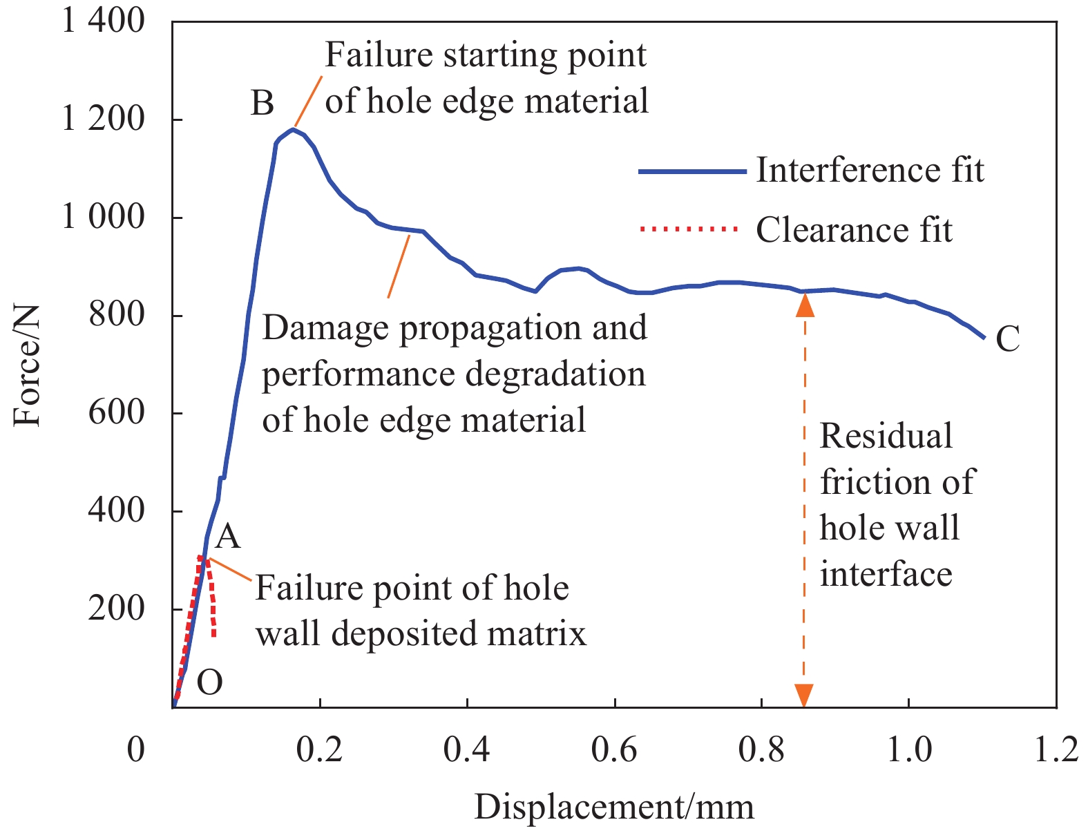
![]()
图 6 C/SiC试件的铆钉顶出静强度载荷-位移曲线对比
Figure 6. Comparison of static strength load-displacement curves of rivet push-out test pieces of C/SiC
![]()
图 7 C/SiC铆钉单元试件的顶出静强度破坏形貌对比
Figure 7. Comparison of push-out static strength failure morphology of C/SiC test units with rivets
![]()
图 8 C/SiC铆钉顶出疲劳强度试验测试结果及拟合曲线
Figure 8. Test results and fitting curves of rivet push-out fatigue strength test of C/SiC
![]()
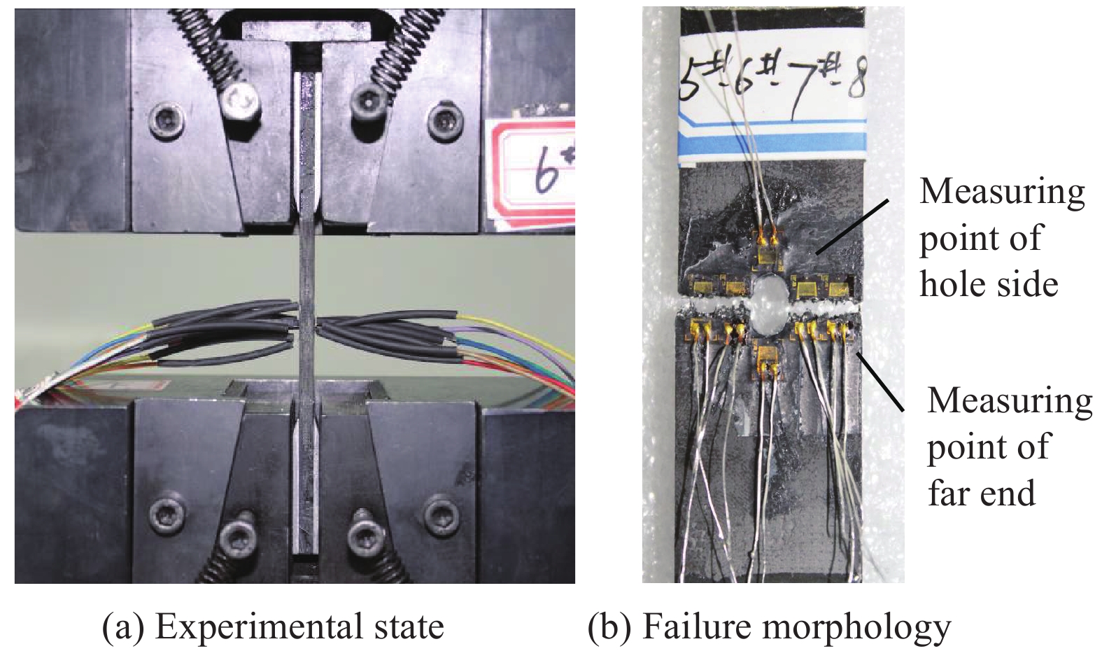
图 9 C/SiC开孔试样的试验状态和拉伸破坏形态
Figure 9. Experimental state and tensile failure morphology of C/SiC specimen with opening-hole
![]()
图 10 C/SiC单独开孔及铆钉单元试件的拉伸测试性能比较
Figure 10. Comparison of tensile test performance between opening-hole and rivet-test units of C/SiC
![]()
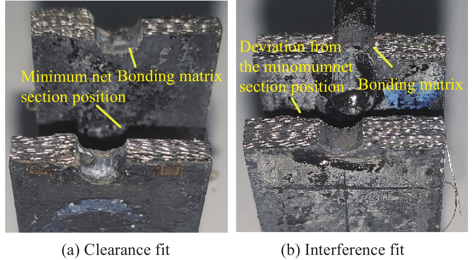
图 11 C/SiC铆钉单元试件拉伸破坏形貌
Figure 11. Tensile failure morphology of C/SiC test units with rivets
![]()
图 12 C/SiC单独开孔与铆钉过盈装配试件的拉伸应力-应变曲线
Figure 12. Tensile stress-strain curves of samples with opening-hole and interference fitting test units with rivets of C/SiC
![]()
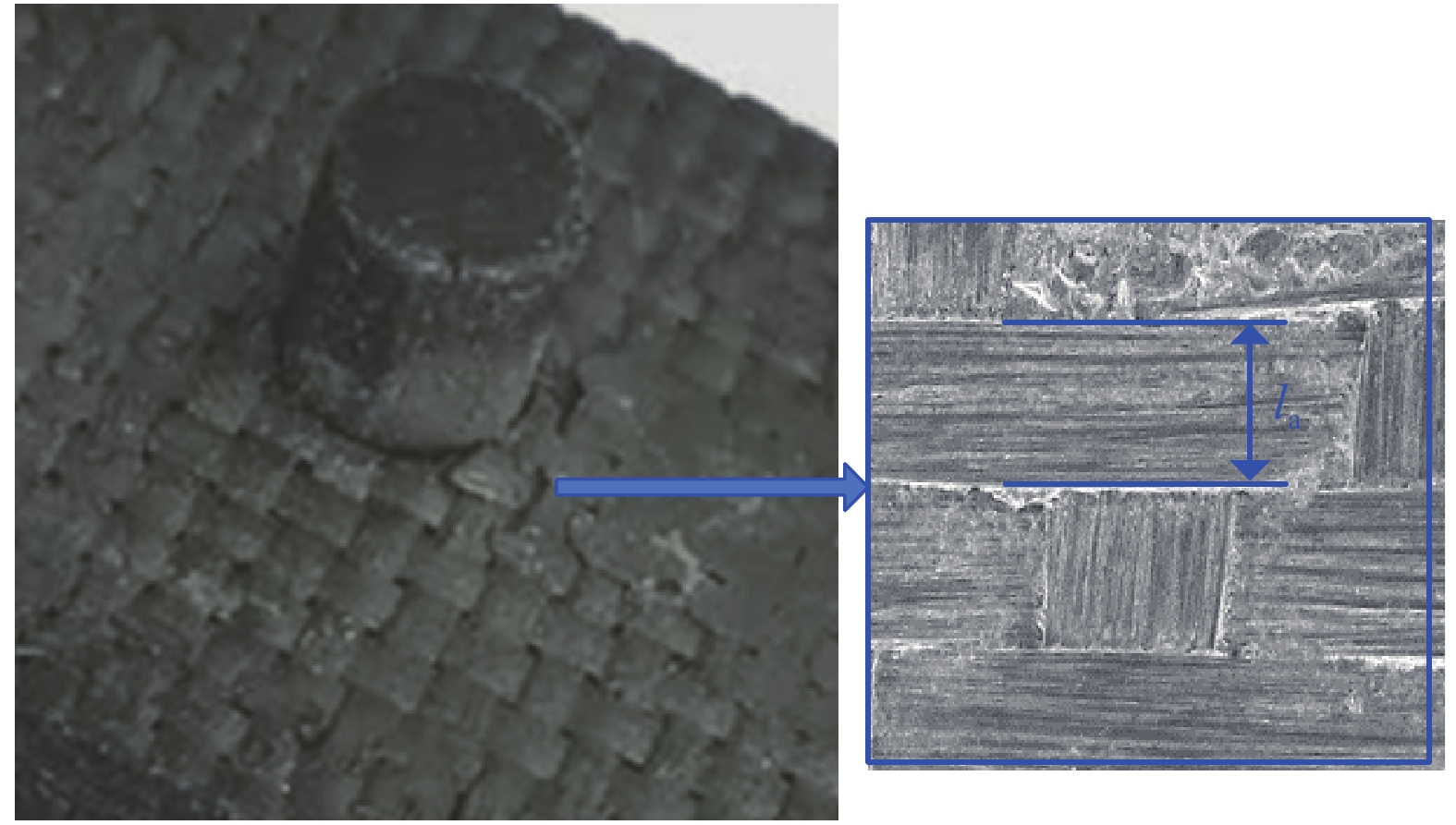
图 13 过盈装配C/SiC铆钉在静载荷顶出试验时的破坏局部特征
Figure 13. Local failure characteristics of interference-fitting C/SiC rivet in static push-out test
la—Width of the fiber bundle
![]()
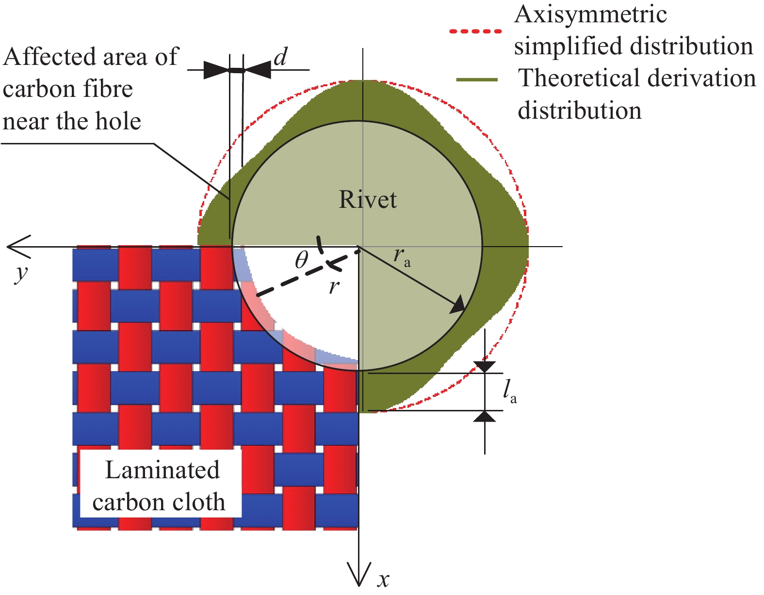
图 14 铆钉过盈装配的几何关系以及纤维偏折/材料破坏的绕中心轴分布示意图
Figure 14. Geometry relation of rivet interference fit and fiber deflection/material failure distribution around central axis
d—Magnitude of interference; r—Distance from center of rivet hole; ra—Theoretical radius of rivet; θ—Angle with the direction of carbon cloth layer
![]()
图 15 不同厚度位置孔边纤维偏折计算及与实测对比
Figure 15. Calculation of fiber deflection at different thickness positions and comparison of measured results
![]()
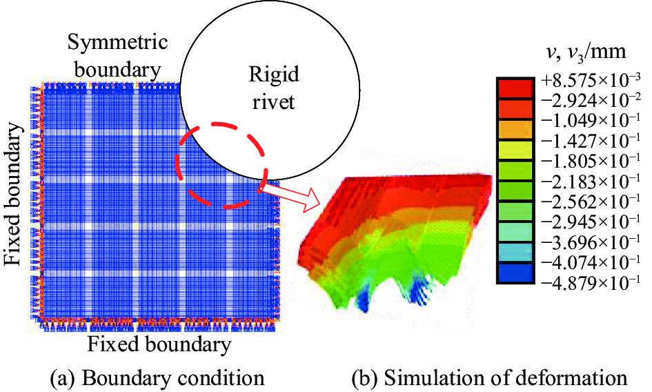
图 16 采用虚拟纤维的铆钉装配数值建模
Figure 16. Numerical simulation of rivet assembly using virtual fiber
v—Deformation
![]()
图 17 采用虚拟碳纤维和SiC实体建模的铆钉装配模型
Figure 17. Rivet assembly model based on virtual carbon fiber and SiC solid
![]()
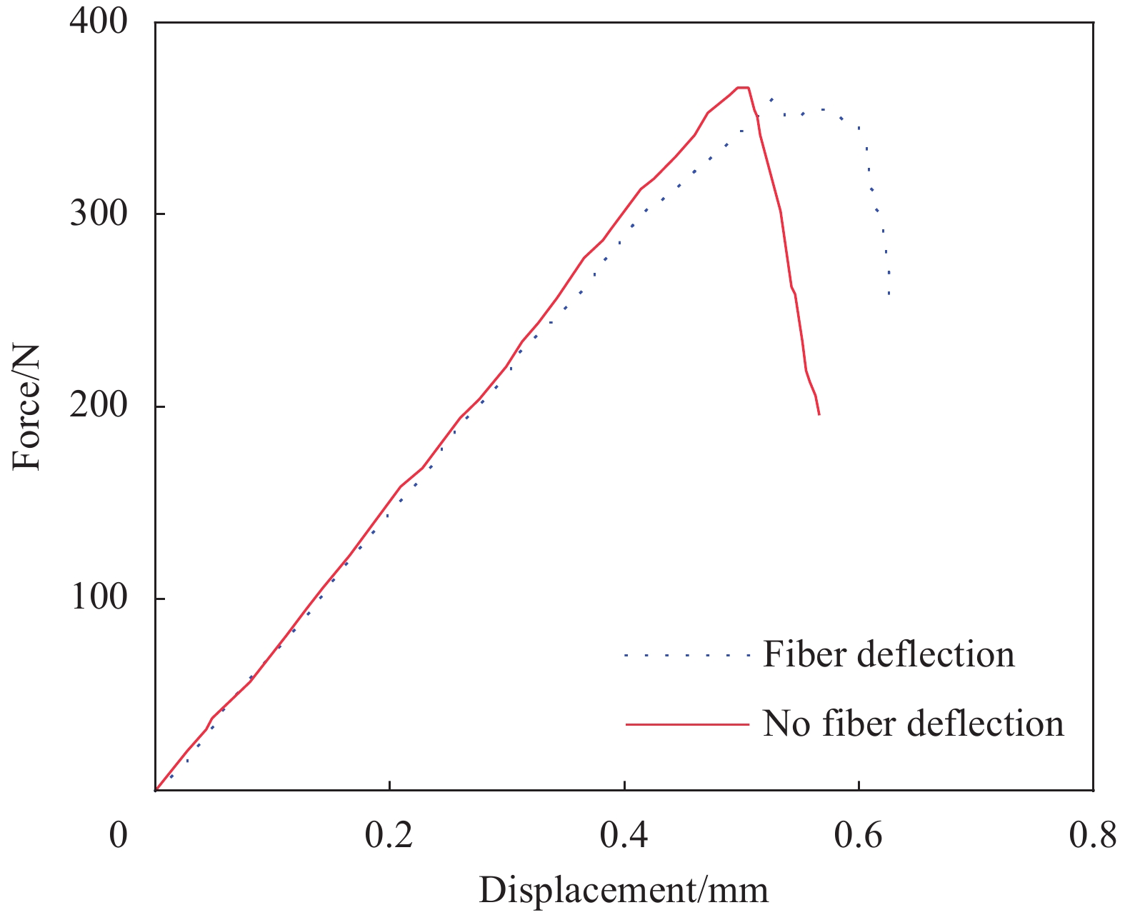
图 18 仅考虑虚拟纤维不同几何状态的C/SiC铆钉顶出计算结果
Figure 18. C/SiC rivet push-out calculation results only considering different geometric states of virtual fiber
![]()
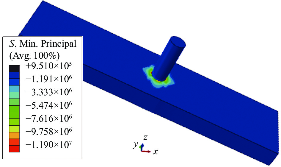
图 19 铆钉过盈装配的C/SiC孔边预应力数值模拟结果
Figure 19. Numerical simulation results of pre-stress around hole in C/SiC rivet interference fitting model
S—Stress (Pa)
![]()
图 20 C/SiC开孔和含铆钉试样的孔边拉伸应力分布
Figure 20. Tensile stress distribution near hole edge of opening-hole and rivet fitting C/SiC specimen
W—Plate width; σθ—Circumferential stress; σr—Radial stress; σy—Tensile stress at the edge of the hole; da—Distance from hole edge
表 1 C/SiC材料及组分材料力学性能
Table 1 Mechanical properties of the C/SiC and component materials
Property Value Elastic modulus Ex(Ey) of C/SiC/GPa 115 Elastic modulus Ez of C/SiC/GPa 35 Poisson's ratio μxy of C/SiC 0.05 Poisson's ratio μxz(μyz) of C/SiC 0.01 Shear modulus Gxy of C/SiC/GPa 35 Shear modulus Gxz(Gyz) of C/SiC/GPa 32 Elastic modulus E1 of carbon fiber/GPa 124 Elastic modulus E2(E3) of carbon fiber/GPa 14 Shear modulus G23 of carbon fiber/GPa 18 Shear modulus G12(G13) of carbon fiber/GPa 20 Poisson's ratio μ12(μ13) of carbon fiber 0.17 Poisson's ratio μ23 of carbon fiber 0.01 Elastic modulus E of SiC matrix with voids/GPa 150 Shear modulus G of SiC matrix with voids/GPa 70 Poisson's ratio μ of SiC matrix with voids 0.08  下载: 导出CSV
表 2 C/SiC单独开孔状态下的强度特征长度
Table 2 Strength characteristic length of C/SiC under the condition of opening
Hole radius
ra/mmTensile strength
σN/MPaσN/σ0 Characteristic
length da/mm0 212.0 1 — 1.0 186.0 0.877 1.38 1.75 159.3 0.751 1.32 2.0 152.0 0.717 1.32 2.75 136.1 0.642 1.39 Note: σ0—Tensile failure stress of no opening-hole.
下载: 导出CSV
-
[1] 韩国凯, 解维华, 孟松鹤, 等. 防隔热一体化复合材料整体性能优化设计方法[J]. 复合材料学报, 2019, 36(2): 450-460. HAN Guokai, XIE Weihua, MENG Songhe, et al, Optimization design method of integrated thermal protection/insulation composite material[J]. Acta Materiae Compositae Sinica, 2019, 36(2): 450-460(in Chinese).
[2] 张立同. 纤维增韧碳化硅陶瓷复合材料: 模拟、表征与设计[M]. 北京: 化学工业出版社, 2009. ZHANG Litong. Fiber-reinforced silicon carbide ceramic composites: Modelling, characterization and design[M]. Beijing: Chemical Industry Press, 2009(in Chinese).
[3] 孟松鹤, 杨强, 霍施宇, 等. 一体化热防护技术现状和发展趋势[J]. 宇航学报, 2013, 34(10):1295-1302. DOI: 10.3873/j.issn.1000-1328.2013.10.001 MENG Songhe, YANG Qiang, HUO Shiyu, et al. State-of-arts and trend of integrated thermal protection systems[J]. Journal of Astronautics,2013,34(10):1295-1302(in Chinese). DOI: 10.3873/j.issn.1000-1328.2013.10.001
[4] ZHANG Q M, LI G S. A review of the application of C/SiC composite in thermal protection system[J]. Multidiscipline Modeling in Materials and Structures,2009,5(2):199-203. DOI: 10.1163/157361109787959903
[5] HUDSON L D, STEPHENS C A. X-37 C/SiC ruddervator subcomponent test program[C]//NASA 2009 Annual Meeting. Houston: NASA, 2009.
[6] 杜善义. 先进复合材料与航空航天[J]. 复合材料学报, 2007, 24(1):1-11. DOI: 10.3321/j.issn:1000-3851.2007.01.001 DU Shanyi. Advanced composite materials and aerospace engineering[J]. Acta Materiae Compositae Sinica,2007,24(1):1-11(in Chinese). DOI: 10.3321/j.issn:1000-3851.2007.01.001
[7] ZOU P, CHEN X M, CHEN H, et al. Damage propagation and strength prediction of a single-lap interference-fit laminate structure[J]. Frontiers of Mechanical Engineering,2020,15(4):558-570. DOI: 10.1007/s11465-020-0591-5
[8] 邹鹏, 曲凡. 复合材料衬套螺栓干涉连接安装过程损伤机制[J]. 复合材料学报, 2022, 39(5):2449-2459. DOI: 10.13801/j.cnki.fhclxb.20210616.007 ZOU Peng, QU Fan. Damage mechanism of composite sleeve-type bolt interference fit structure during the installation process[J]. Acta Materiae Compositae Sinica,2022,39(5):2449-2459(in Chinese). DOI: 10.13801/j.cnki.fhclxb.20210616.007
[9] 宋祚禹, 王西昌, 曹正华, 等. 碳纤维/聚脂亚胺树脂基复合材料开孔件的连接力学性能[J]. 航空制造技术, 2009(z1):139-140, 144. DOI: 10.3969/j.issn.1671-833X.2009.z1.043 SONG Zuoyu, WANG Xichang, CAO Zhenghua, et al. Joint mechanical properties of open-hole carbon fiber reinforced polyimide composites[J]. Aeronautical Manufacturing Technology,2009(z1):139-140, 144(in Chinese). DOI: 10.3969/j.issn.1671-833X.2009.z1.043
[10] 赵丽滨, 徐吉峰. 先进复合材料连接结构分析方法[M]. 北京: 北京航空航天大学出版社, 2015. ZHAO Libin, XU Jifeng. Analysis method for advanced composite joints[M]. Beijing: Beihang University Press, 2015(in Chinese).
[11] 张毅. CVI-2D C/SiC复合材料铆接单元的力学行为与失效机制[D]. 西安: 西北工业大学, 2017. ZHANG Yi. Mechanical behaviors and failure mechanisms of z-pinned joints for 2D C/SiC composite prepared by chemical vapor infiltration[D]. Xi'an: Northwestern Polytechnical University, 2017(in Chinese).
[12] ZHANG Y, ZHANG L T, HE J Y, et al. Modelling shear behaviors of 2D C/SiC Z-pinned joint prepared by chemical vapor infiltration[J]. Ceramics International,2018,44(6):6433-6442. DOI: 10.1016/j.ceramint.2018.01.038
[13] LEONE F A, DAVILA C G, CIROLAMO D G. Progressive damage analysis as a design tool for composite bonded joints[J]. Composites Part B: Engineering,2015,77:474-483. DOI: 10.1016/j.compositesb.2015.03.046
[14] LI G D, WU X F, ZHANG C R, et al. Theoretical simulation and experimental verification of C/SiC joints with pins or bolts[J]. Materials & Design,2014,53:1071-1076.
[15] HE Z B, ZHANG L T, ZHANG Y, et al. Microstructural characterization and failure analysis of 2D C/SiC two-layer beam with pin-bonded hybrid joints[J]. International Journal of Adhesion and Adhesives,2015,57:70-78. DOI: 10.1016/j.ijadhadh.2014.10.008
[16] ZHANG X Y, SUO T, WANG B, et al. Fatigue behavior and residual strength evolution of 2D C/SiC Z-pinned joints prepared by chemical vapour infiltration[J]. Journal of the European Ceramic Society,2019,39:3575-3582. DOI: 10.1016/j.jeurceramsoc.2019.04.051
[17] ZOU P, ZHANG K F, LI Y, et al. Bearing strength and failure analysis on the interference-fit double shear-lap pin-loaded composite[J]. International Journal of Damage Mechanics,2016,27(2):179-200.
[18] ZOU P, LI Y, ZHANG K F, et al. Mode I delamination mechanism analysis on CFRP interference-fit during the installation process[J]. Materials & Design,2017,116:268-277. DOI: 10.1016/j.matdes.2016.11.063
[19] LI Y, XIAO P, LUO H, et al. Fatigue behavior and residual strength evolution of 2.5D C/C-SiC composites[J]. Journal of the European Ceramic Society,2016,36(16):3977-3985. DOI: 10.1016/j.jeurceramsoc.2016.07.009
[20] 杨晔楠, 赵美英, 周银华. 过盈配合对复合材料多钉连接强度的影响研究[J]. 航空工程进展, 2012, 3(3):311-316. DOI: 10.3969/j.issn.1674-8190.2012.03.012 YANG Yenan, ZHAO Meiying, ZHOU Yinhua. Study on effect of interference fit on joint strength for multi-fasteners in composites[J]. Advances in Aeronautical Science and Engineering,2012,3(3):311-316(in Chinese). DOI: 10.3969/j.issn.1674-8190.2012.03.012
[21] 邹鹏. 复合材料干涉螺接结构损伤萌生与扩展机理研究[D]. 西安: 西北工业大学, 2017. ZOU Peng. Research on the damage initiation and evolution mechanism of composite interference-fit bolted structures[D]. Xi'an: Northwestern Polytechnical University, 2017(in Chinese).
[22] HWAN C L, TSAI K H, CHEN W L, et al. Strength prediction of braided composite plates with a center hole[J]. Journal of Composite Materials,2011,45(19):1991-2002. DOI: 10.1177/0021998311399483
[23] TAN Z Y, DONG W L, MEI J, et al. Strength and mechanical response of C/C composite open-hole and bolted plates[J]. Materials Testing,2017,59(9):774-778. DOI: 10.3139/120.111067
-
期刊类型引用(0)
其他类型引用(1)
-


计量
- 文章访问数: 743
- HTML全文浏览量: 398
- PDF下载量: 71
- 被引次数: 1
