Parametric effects of low-velocity impact response and damage mode of aluminum honeycomb sandwich panels
-
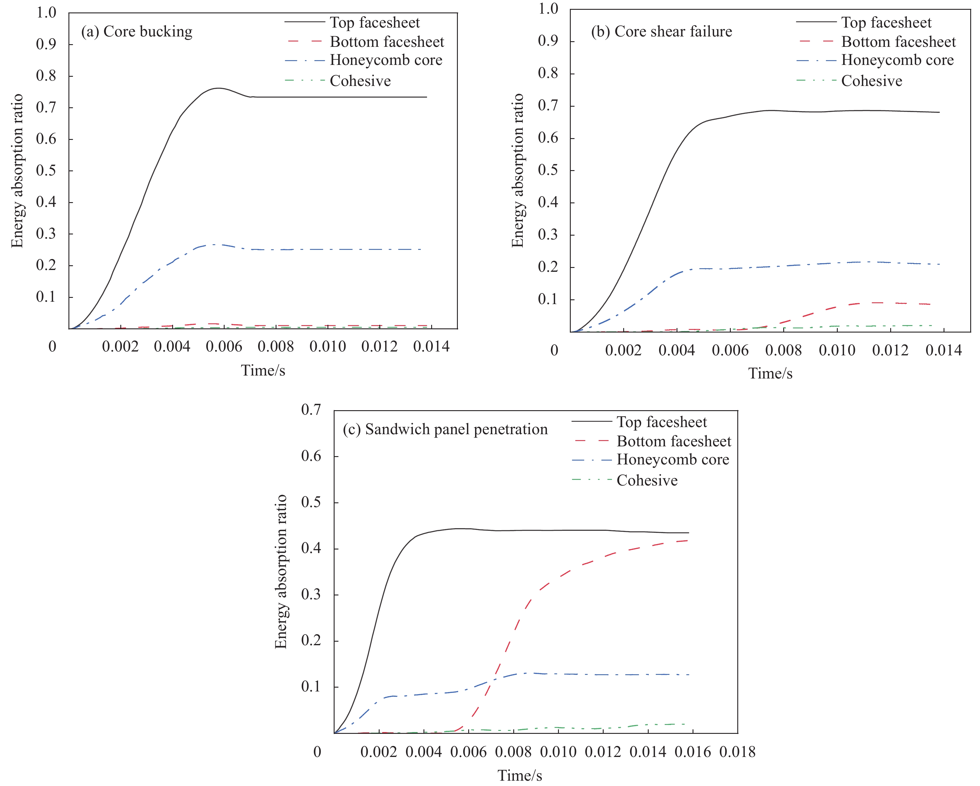
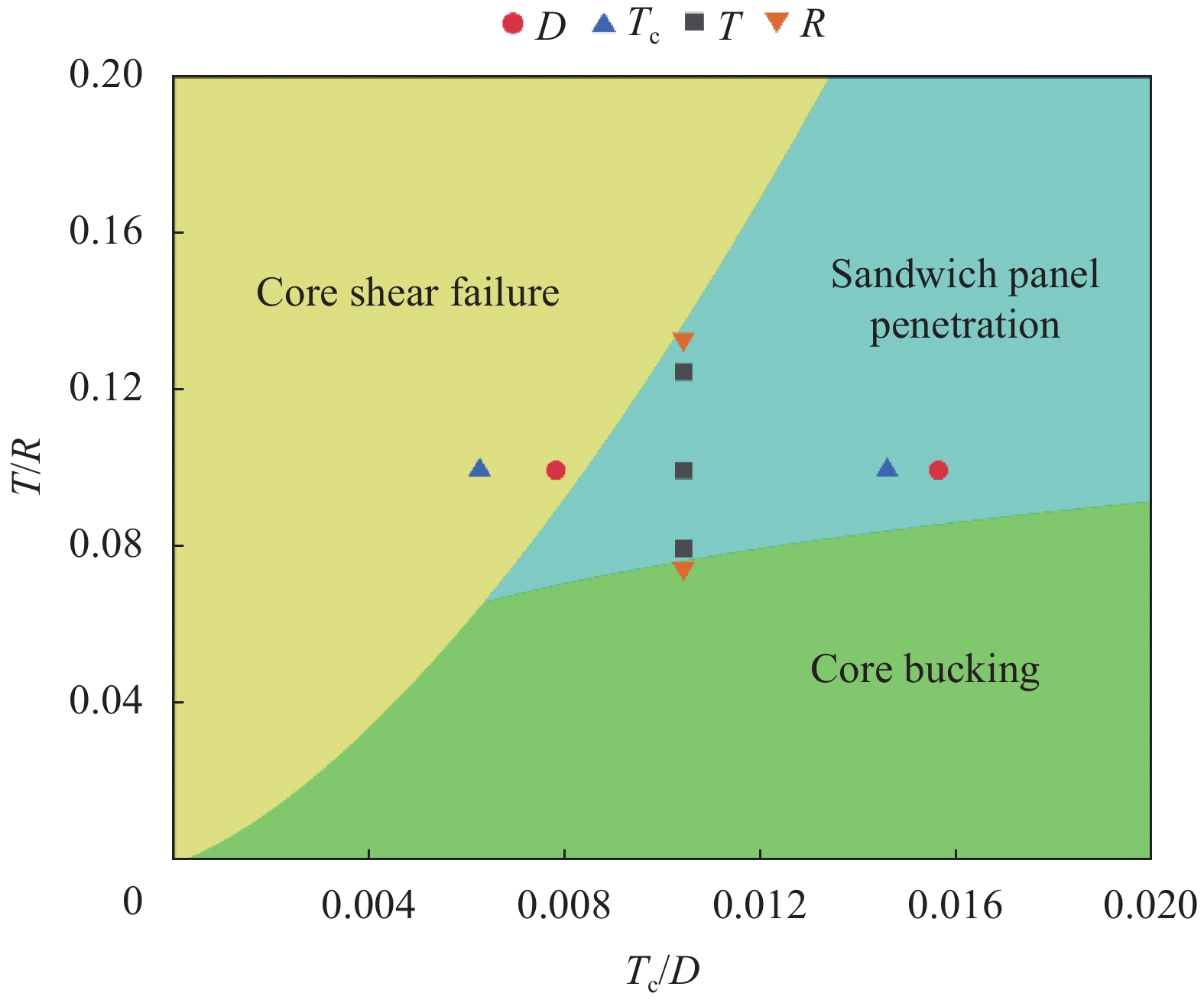
摘要: 以铝蜂窝夹层板为对象,通过低速落锤试验及包含面板、胶层及蜂窝的细节仿真模型,探究了蜂窝胞元直径、蜂窝壁厚、面板厚度及冲头半径参数影响下低速冲击响应曲线及损伤模式的变化情况,确定在试验工况下的3种损伤模式:芯层屈曲、芯层剪切及夹层板穿透,其中芯层剪切模式具有更好的吸能分布。结果表明:蜂窝胞元直径与蜂窝壁厚对冲击响应与损伤模式具有类似的影响,面板厚度增加可以较大程度地提升抗冲击性能,冲头半径的大小会显著影响损伤模式。在此基础上建立与上述参数相关的损伤模式极限载荷公式,绘制相应的损伤模式图,为铝蜂窝夹层板的抗冲击设计提供参考。Abstract: Taking the aluminum honeycomb sandwich panel as the object, through the low-speed drop weight test and the detailed simulation model including the panel, the adhesive layer and the honeycomb, the changes of low-speed impact response curve and damage mode under the influence of the honeycomb cell diameter, honeycomb wall thickness, panel thickness and punch radius parameters were studied. Three damage modes under the test conditions were determined: Core buckling, core shear and sandwich panel penetration, among which the core shear mode has better energy absorption distribution. The results show that the honeycomb cell diameter and the honeycomb wall thickness have similar effects on the impact response and damage mode. The increase of the panel thickness can greatly improve the impact resistance, and the size of the punch radius will significantly affect the damage mode. On this basis, the damage mode limit load formula related to the above parameters was established, and the corresponding damage mode diagram was drawn to provide a reference for the impact resistance design of aluminum honeycomb sandwich panels.
-
蜂窝结构拥有隔热性、吸能性、轻质性等特点,广泛用于航空航天、汽车、建筑和冲击防护等领域[1-2]。根据单胞构型的不同,蜂窝结构可以分为六边形、四边形、三角形、圆形和异形蜂窝等[3]。以蜂窝受到面内压缩时横向变形的特点又可分为传统蜂窝和负泊松比蜂窝[4-5]。
使用传统工艺制作复杂结构的蜂窝难度大、成本高[6],当前相关研究多使用熔融式3D打印技术制造各形蜂窝[7]。但基于热塑性树脂打印出的蜂窝因树脂力学性能不足表现出结构强度和刚度较弱等缺点[8]。通过在树脂中加入高性能纤维可有效增强结构的力学性能[9]。国内外学者已开展了相关研究。Quan等[10]使用3D打印技术制造了一种连续芳纶纤维增强聚乳酸(PLA)基材料的负泊松比内凹六边形蜂窝结构,对该结构进行了面内压缩试验,同时设置PLA对照组,在质量增加6%的情况下,复材件相比PLA件在抗压刚度和吸能方面性能可分别提高87%和100%。Cheng等[11]使用碳纤维和特制基体制造了连续碳纤维3D打印轻质蜂窝,研究了结构在热激励下的自恢复特性,利用碳纤维自身的电阻属性,由碳纤维充当加热器,结构压缩后对内部碳纤维通电流,结构可在碳纤维发热后恢复部分形变。Zeng 等[12]研究了由碳纤维增强树脂基体制成的六边形和四边形单胞蜂窝结构,对该结构进行了压缩性能和吸能性能研究,并在压缩试验后将试验件放置在70℃的温度箱中开展形状恢复测试。张亚男[13]打印了芳纶纤维增强热塑性聚氨酯(TPU)基蜂窝,在减少单胞尺寸,提高结构相对密度后可增强蜂窝的抗压缩性能。
当前蜂窝领域研究热点集中于六边形蜂窝、增强型蜂窝及负泊松比蜂窝[14-16]。六边形蜂窝在面外压缩上优异的承载能力,而在面内压缩性能上,相同密度下的圆形蜂窝相较六边形蜂窝有更高的刚度和抗压强度[17],同时具有更好的吸能性能[18]。在成型工艺方面,使用连续纤维3D打印成型试验件时,圆形蜂窝相较于多边形蜂窝在成型路径规划上有较大优势[19-20],例如,在保证纤维连续性的情况下,圆形蜂窝可在任意平面阵列排布下做到零重复路径,能够提高成型效率并减少材料浪费。圆形蜂窝成型路径呈圆弧形,路线平滑且无突变角度,利于成型时纤维束的均匀分布,可减少纤维束滑移等成型缺陷[21]。
基于上述原因,本文在传统圆形蜂窝(Circular honeycomb,CH)结构的基础上,通过向单胞内引入树叶形增强结构,构建了单向增强圆形蜂窝(Single enhanced CH,SEH)和双向增强圆形蜂窝(Double enhanced CH,DEH)。使用碳纤维(CF)作增强体、PLA为基体的预浸渍丝材为原材料,3D打印制造了连续碳纤维增强试验件,同时设置PLA试验件为对照组,讨论了蜂窝结构设计、材料体系和路径规划对结构面内压缩的抗压性能、吸能性能和变形模式的影响规律。
1. 实验材料及方法
1.1 原材料及3D打印方法
本文使用一台自行研发的连续纤维3D打印设备制造CF增强试验件。当前复合材料3D打印主要分为原位浸渍工艺和预浸渍工艺[22-23],本设备基于预浸渍工艺研制,如图1(a)所示。采用预浸渍丝材作为打印原料。预浸渍丝材以CF为增强体,PLA为基体。碳纤维(HTA40-E15-1K),单丝直径7 μm,密度1.78 g/cm3,由Toho Tenax公司提供。PLA材料密度1.31 g/cm3,由广东闪锐公司提供。预浸渍丝材使用自研的熔融浸渍设备生产,丝材直径为1 mm,纤维体积含量为8.3vol%。
本设备主要由卷线盘、进给机构、喷头组件、打印平台、运动机构和控制模块组成。预浸渍丝材储存在卷线盘内,进给机构将丝材按成型需求量送入到喷头组件。成型时,喷头组件内的加热电阻将喷嘴升温至基体熔融温度以上,融化的树脂混合碳纤维束从喷嘴处挤出后沉积粘附至打印平台上。设备按加工路径控制运动机构上的电机移动喷嘴,单层打印结束后打印平台下降一个层高的距离,如此循环,最终完成试验件的制造,3D打印加工示意图如图1(b)所示,成型完成的试验件如图2所示。相较于传统打印设备,本设备对卷线盘、挤出机和喷头组件进行了重新设计,可适配带纤维束的小直径丝材。通过在丝材外包覆低阻尼保护管,优化喷嘴外形,可减少系统对丝材的摩擦,起到保护丝材,减少纤维损伤的作用。
1.2 蜂窝几何设计
CH是由多个圆形单胞在横向和竖向以阵列形式相切排列构成的,蜂窝各方向力学性能较均匀,但存在孔隙率高,受大位移压缩时易发生侧壁塌缩导致结构失效的情况。通过向蜂窝内添加支撑可有效提升结构的承载能力和吸能特性[24]。
SEH、DEH两种蜂窝是在CH基础上增加树叶形支撑结构得到的。以DEH为例,其在横竖两方向上增加了支撑,单胞外圆的半径r1=10 mm,横竖两处树叶形支撑由4段圆弧组成,圆弧的圆心设置于单胞外圆上的a、b、c、d这4点,圆弧半径r2=√2r1,绘制4段弧度 \phi ={90}^{°} 圆弧,见图3(a)。此时,圆弧均被等分为3段小圆弧,存在几何关系:
\overset\frown{\text{ae}}=\overset\frown{\text{ef}}=\overset\frown{\text{fa}} (1) 由点a、e、f围成的图形近似于等边三角形,力学性能较稳定。考虑原材料制作和设备成型尺寸限制,蜂窝结构采用 3\times 3 单胞构型。试件的设计参数如表1所示。
表 1 蜂窝结构设计参数Table 1. Geometric parameters of honeycomb{r}_{1} /mm {r}_{2} /mm \phi /(°) L/mm H/mm q/mm 10 14.14 90 60 60 20 Notes: {r}_{1} —Radius of honeycomb outer circle; q—Thickness of honeycombs. SEH即在DEH基础上保留竖向支撑,去掉横向支撑,其余几何参数保持一致。CH结构仅保留外圆轮廓,其余参数一致。
蜂窝结构的相对密度是影响结构力学性能和变形模式的重要参数,本文中结构相对密度的计算公式如下:
\stackrel-{\;\rho }=\frac{{\rho }^{*}}{{\rho }_{\mathrm{s}}}=\frac{{A}_{\mathrm{s}}}{A} (2) 式中: {\rho }^{*} 表示蜂窝结构的表观密度; {\rho }_{\mathrm{s}} 为蜂窝结构的材料密度; {A}_{\mathrm{s}} 表示蜂窝结构的实际横截面积; A 表示蜂窝结构的总横截面积(A=LH,L表示试件宽度,H表示试件高度)。
1.3 路径规划和试件制造
相较传统3D打印技术,在连续纤维3D打印中,引入高性能纤维束增加了结构件力学性能,也同时增加了纤维束成型路径规划的环节。通常,一种结构件拥有多种加工路径可供选择。本文以提高结构力学性能、降低缺陷发生率、保证纤维连续性为目标设计了3种蜂窝结构的成型路径。
CH的成型路径如图3(c)所示,数字和箭头分别表示成型路径的顺序和方向,虚线表示第一层成型时,喷嘴的首次进入路径。CH成型路径以加工平面右下角为起点,沿顺时针方向以螺旋形依次生成其余单胞,完成路径16后又回到起点。由于每一层的打印路径起点和终点均重合,因此每层的成型路径相同。SEH结构的成型路径是在CH结构的成型路径基础上在每处单胞内加入竖向增强的成型路径,如图3(b)所示。
DEH在横竖两方向均有支撑,存在多种成型路径方案可供选择,为发挥碳纤维优异的抗拉性能并提升结构刚度,为DEH结构设计了一种“支撑一体化成型”路径,如图4所示。该路径规划策略是将结构同方向的3处树叶形支撑依次打印,然后在后续成型中加入单胞外圆的成型路径,DEH打印过程见图5。
因在同一打印层中,纤维束路径存在同多次交叉和轨迹角度较大偏转,为确保可行性,在试验前进行了工艺验证。单束1 K碳纤维纱束层厚约0.05 mm,在将3D打印层高tz设置为0.4 mm,喷嘴温度 {T}_{1} 为200℃,同时令喷嘴经过节点时停留0.5 s,可使节点处的上一层基体融化,线材之间二次熔融压实,通过以上优化措施,可满足有4次交叉时,节点处平滑。为避免因轨迹角度急剧偏转,发生纤维束剥离导致成型失败,设备对沉积到成型平面后的纤维束进行冷却散热,让熔融态基体快速固化,可有效提升打印质量。
连续纤维3D打印制造试验件的成型参数如表2所示,PLA对照组的3种蜂窝结构使用桌面式熔融沉积制造(FDM) 3D打印机制造,由广东闪锐公司提供,PLA材料与CF增强组所用PLA材料相同。每种构型的试验件制作5个,相关参数如表3所示。
表 2 打印成型参数Table 2. Parameters of printing processtz/mm {V}_{1} /(mm·min–1) {T}_{1} /℃ {n}_{1} {t}_{\mathrm{H}} /mm 0.4 130 200 50 1.7 Notes: tz—Thickness of layer; {V}_{1} —Speed of moulding; {T}_{1} —Nozzle temperature; {n}_{1} —Number of layers; {t}_{\mathrm{H}} —Honey-comb wall and strut thickness. 表 3 蜂窝试验件参数Table 3. Parameters of honeycomb specimensType L /mm H /mm q/mm m/g \stackrel{-}{\rho } CH-PLA 61 61 20 18.1 0.24 CH-CF 61 61 20 18.8 0.24 SEH-PLA 61 61 20 31.1 0.40 SEH-CF 61 61 20 32.1 0.40 DEH-PLA 61 61 20 43.3 0.57 DEH-CF 61 61 20 44.9 0.57 Notes: m—Mass of specimen; \stackrel{-}{\rho } —Relative density; PLA—Poly-lactic acid. 1.4 试验设备及试验设置
使用MTS Model E45型试验机,参照GB/T 18942—2003[25]标准对蜂窝结构进行准静态压缩试验,蜂窝试验件放置在试验机上下两块圆形压头之间,下压头固定在试验机平台上,上端压头安装在可移动的横梁上,试验设备及加载方式如图6所示。试验时上端压头施加向下的位移载荷,加载速率为3 mm/min,压缩位移加载至39 mm以上(名义应变 {\varepsilon }_{y} > 0.65 )。上端压头的载荷通过力传感器将支反力数据传输给控制端,同时在试验机外放置了摄像装置,对压缩过程中试验件宏观变形情况进行记录。
在面内压缩过程中,蜂窝结构的名义应力和名义应变计算公式如下:
\sigma =\frac{{R}_{\mathrm{f}}}{{A}_{\mathrm{t}}} (3) {\varepsilon }_{y}=\frac{\mathrm{\Delta }y}{H} (4) 式中: {R}_{\mathrm{f}} 为上端压头与蜂窝结构之间的反作用力;At为试件的垂向初始横截面积,即At=Lq,q表示试件厚度; \text{Δ}y 为上端压头的压缩位移。
2. 结果与讨论
2.1 蜂窝结构的准静态压缩响应
CH、SEH和DEH在准静态面内压缩时的名义应力-应变曲线如图7所示。为方便表述,将试验件名称简化为构型加材料体系英文缩写,如碳纤维增强组DEH试验件用DEH-CF表示。由曲线可知,两种材料体系的SEH和DEH准静态压缩响应均具有多胞材料的典型应力响应特征,即结构在压缩过程呈现出弹性阶段、平台阶段和密实化阶段3个时期。
SEH和DEH的弹性阶段发生在压缩过程初期( {\varepsilon }_{y} < 0.1 ),结构各单胞发生均匀的弹性变形,且CF增强组的弹性阶段期大于PLA对照组。随压缩量增加,结构进入到平台阶段,结构的侧壁和支撑发生弯曲、接触和断裂,单胞出现局部密实化,应力在波动中逐渐升高。当压缩量进一步增大,结构由局部密实化逐渐发展成整体密实化,进入到密实化阶段,此时支反力急剧提升。分析各结构的应力-应变曲线可知,结构的各应力响应特征阶段期随结构相对密度 \stackrel{-}{\rho } 的增加而变短。例如,DEH结构的3个阶段期均短于SEH和CH结构。 \stackrel{-}{\rho } 值较高的蜂窝结构,其内单胞内部空间有较多支撑填充,受压时侧壁和支撑会较早发生接触,影响结构的应力响应。
为探究不同材料体系对结构的抗压性能的影响,取弹性阶段峰值应力为结构抗压强度,结果如图8所示。采用连续纤维三维打印后,CH、SEH和DEH这3种结构在质量增加约4%的情况下,抗压强度相较PLA对照组分别提升了82.88%、42.73%、39.89%。结果显示,在PLA中加入碳纤维束有效提升了结构的面内抗压缩性能。
2.2 蜂窝结构的变形模式
CH、SEH和DEH结构在面内压缩时结构的变形模式如图9~图11所示。
对于CH结构,CH-PLA在 {\varepsilon }_{y}=0.2 时,部分单胞侧壁受压后发生弯折,可见塑性断口(图9(a)圆圈处),结构出现局部坍塌,相同应变下的CH-CF仍为整体变形。在 {\varepsilon }_{y}=0.4 时,CH-PLA在斜45°方向上的单胞塌缩,到 {\varepsilon }_{y}=0.6 时,单胞塌缩范围继续扩展,CH-PLA组因斜向单胞断裂塌缩,整体变形呈“X”型。而碳纤维增强的CH-CF组,其侧壁抗弯和抗压性能较对照组有明显增强,压缩过程未出现单胞过早断裂导致结构局部失效的情况,结构变形模式也趋于整体变形。
对于SEH结构,SEH-PLA在 {\varepsilon }_{y}=0.2 时,底层3个单胞塌缩,单胞的侧壁和树叶形支撑发生了弯折和断裂,可见塑性断口。同应变下SEH-CF的多处单胞的侧壁和支撑发生弯折,但未见断裂。在 {\varepsilon }_{y}=0.4 时,两组蜂窝均因斜向单胞塌缩,变形呈“X”型,但PLA组内弯折的侧壁和支撑多已断裂,而碳纤维组则是侧壁与支撑在压缩后屈曲并相互贴合,结构并未断裂。在 {\varepsilon }_{y}=0.6 时,两种结构处于密实化阶段前期,单胞均已塌缩。
对于DEH结构,DEH-PLA组在 {\varepsilon }_{y}=0.2 时,中层和底层部分单胞支撑发生断裂,同应变下的DEH-CF结构中层单胞的横向树叶形支撑出现明显的横向拉伸(图11(b)箭头处),但单胞未出现侧壁和支撑断裂。在 {\varepsilon }_{y}=0.4 时,DEH-PLA结构单胞内的横向支撑均发生断裂,PLA抗拉强度已无法承受结构的横向扩展应力,同阶段DEH-CF单胞的侧壁和支撑均有弯折和塌缩,但未断裂。在 {\varepsilon }_{y}=0.6 时,两种结构均处于密实化阶段,结构趋于整体密实化,单胞完全塌缩。
由上述6组分析可知,在结构中引入碳纤维增强了单胞的抗压和抗弯性能,改变了蜂窝结构的变形模式。在受压时,纤维增强结构单胞变形更加均匀,局部塌缩减少。
2.3 蜂窝结构的破坏模式
试验结束后,使用Hirox KH-7700高倍光学显微镜对试验件的典型断口等失效部位进行拍照。结构的破坏模式受材料体系影响较大,图12(a)是压缩后的CH-PLA试件,其中标识1处为蜂窝中相邻单胞节点处的失效断面,侧壁完全断裂并弯折,断裂模式为脆性断裂,断口表面有锯齿状突起。标识2处是结构下层一处单胞侧壁的断面,断口平整,断裂模式同样为脆性断裂。结构失效是由节点处侧壁过早断裂而引起的。
图12(b)是压缩后的CH-CF试件,标识3处为相邻两单胞连接处的失效断面,该处侧壁未完全断裂,初始于右侧的裂纹扩展到碳纤维束处便停止扩展(箭头处),裂纹中间断口有碳纤维单丝从基体拨出。标识4为上下相邻单胞接合处,侧壁受压后弯曲贴合,纤维束分布均匀无断裂,基体未见明显裂纹。结构失效是由侧壁受压后弯曲失去承载能力而引起的。
SEH和DEH与CH类似,其破坏模式根据材料体系不同有明显差异。PLA组受压后在侧壁和支撑接合处出现较多断口,结构因侧壁和支撑受压后发生塑性断裂而失效。CF组受压后其侧壁和支撑绕节点弯曲,最终相互贴合,未见明显断口,结构因侧壁和支撑受压后弯曲而失效。
由上述分析可知,材料体系影响了蜂窝结构的破坏模式。碳纤维增强组结构的侧壁和支撑抗断裂能力明显增加,连续纤维阻止了裂纹在基体中的传播,有效防止侧壁和支撑在受压后过早断裂,延缓了结构的整体失效。
2.4 DEH结构动态泊松比
采用“支撑一体化成型”路径制作的DEH-CF相较DEH-PLA在压缩时主平面的横向变形上表现出较大差异。DEH-PLA在压缩时,结构在各个特征阶段均朝主平面的横向扩展,在垂直于主平面的侧向平面上变形量较少。DEH-CF在压缩时结构整体横向变形趋势较小,在结构进入到密实化阶段后,相较同时期对照组,其横向的变形增量下降明显,而在侧向平面上出现横向扩展变形,如图13所示。为详细研究DEH结构在压缩时的横向变形机制,本文使用结构动态泊松比参数对变形过程进行分析[26]。蜂窝结构的动态泊松比 \mu 的计算公式如下:
△\stackrel-{L}=\frac{1}{3}\underset{1}{\sum ^{3}}({L}_{{A}_{i}{B}_{i}}-L) (5) \;\mu=-\frac{\varepsilon_x}{\varepsilon_y}=-\frac{\Delta \bar{L} / L}{\varepsilon_y} (6) 式中: △\stackrel{-}{L} 是蜂窝结构在压缩时结构横向位移变化量;L是蜂窝结构的初始宽度; {A}_{i} 、 {B}_{i} (i=1, 2, 3)是横向上蜂窝结构每层单胞两侧端点。
图14给出了两种材料的DEH结构在面内压缩下的动态泊松比-名义应变曲线。从曲线可知,DEH-PLA在压缩过程中结构动态泊松比显著大于DEH-CF,且在DEH-PLA进入到密实化阶段以后( \mu > 0.5 )泊松比有继续增加的趋势,而DEH-CF的泊松比则有下降的趋势。
对DEH-PLA宏观变形过程分析后发现,部分单胞的侧壁和支撑因材料性能不足在压缩过程初期( \mu =0.1 )便发生了塑性断裂(图15圆圈处),单胞失去支撑后迅速坍塌并朝横向扩展,导致结构在压缩响应时表现出较高泊松比特性。
对DEH-CF结构,其内部的纤维路径影响了压缩响应时结构的变形行为。图16中标号为1、2的横向叶形支撑与右端侧壁的纤维束整体相连,标号3的横向支撑与左端侧壁纤维束相连,DEH-CF成型路径可参照图4。试验件右端侧壁变形均匀,整体与右侧虚线齐平,需要注意标号1、2、3所指处的侧壁均有内凹收缩的趋势,这是由横向支撑结构抵抗蜂窝横向变形而牵引侧壁所导致的。3处圆圈所指区域的横向支撑与其对应侧壁无纤维直接相连,仅有树脂基体连接,区域呈现浅白色,基体有剥离的趋势,同时侧壁有不规则变形。值得注意的是,随着压缩响应向密实化阶段发展( \mu > 0.4 ),DEH-CF减缓了主平面的横向扩展,结构厚度方向出现层间开裂。这是CF增强后导致结构主平面横向刚度过高和3D打印层间性能不足共同作用的结果。
因此,“支撑一体化成型”路径规划增强了DEH-CF的横向刚度,在结构受压时,纤维束抵抗侧壁横向扩展的作用明显,结构在压缩过程中呈现出低泊松比的特性。
2.5 蜂窝结构的吸能性能
蜂窝结构拥有优秀的吸能特点,为研究3种蜂窝结构的能量吸收性能,使用比吸能(Specific energy absorption, {S'} )和平均压缩力(Mean crushing force, {M'})参数进行研究。比吸能表示蜂窝结构单位质量吸收的能量,定义公式如下:
{S'}=\frac{{E}_{\mathrm{a}}}{m} (7) 式中, {E}_{\mathrm{a}} 为蜂窝结构在压缩过程中的总吸收能量。 {E}_{\mathrm{a}} 的计算公式如下:
{E}_{\mathrm{a}}={\int }_{0}^{{y}_{\mathrm{d}}}F\mathrm{d}y (8) 式中:y代表压缩位移;F为压缩反力; {y}_{\mathrm{d}} 表示结构在进入致密化阶段时的致密化压缩位移。 {y}_{\mathrm{d}} 由致密化应变 {\varepsilon }_{\mathrm{d}} 换算得出,其定义为
E\left(\varepsilon \right)=\frac{{\displaystyle\int }_{0}^{\varepsilon }\sigma \left(\varepsilon \right)\mathrm{d}\varepsilon }{\sigma \left(\varepsilon \right)} (9) {\left.\frac{\mathrm{d}E\left(\varepsilon \right)}{\mathrm{d}\varepsilon }\right|}_{\varepsilon ={\varepsilon }_{{\rm{d}}}}=0 (10) 式中, E\left(\varepsilon \right) 为蜂窝结构应力应变能与名义应力的比值。公式通常可以得到多个符合条件的 {\varepsilon }_{\mathrm{d}} 解,通常取 {\varepsilon }_{\mathrm{d}} 最大值解为本蜂窝结构对应的致密化应变,该点过后结构由平台阶段进入致密化阶段,压缩应力急剧增大。平均压缩力计算公式如下:
{M'}=\frac{1}{{y}_{\mathrm{d}}}{\int }_{0}^{{y}_{\mathrm{d}}}F\mathrm{d}y (11) 表4给出了各类蜂窝结构的 {\varepsilon }_{\mathrm{d}} 、 {S'} 、 {M'} 参数。由数据可知,增加了竖向树叶形增强的SEH结构相较CH结构吸能特性提升较小,SEH-CF相较CH-CF提升10.98%,而SEH-PLA相较CH-PLA比吸能性能有下降,这与SEH-PLA受压时因材料强度低,支撑过早断裂失效有关。SEH结构在受压时拥有可吸能的塑性铰数目较少且结构横向稳定性差,综合性能提升较小。
表 4 各蜂窝结构的吸能参数Table 4. Energy absorption parameters of each honeycombType {\mathit{\varepsilon }}_{\mathbf{d}} {\mathit{S'}} /(J·g−1) ({S_{\mathrm{CF} }^{\prime}-S_{\mathrm{PLA} }^{\prime} })/{S_{\mathrm{PLA} }^{\prime} } {\mathit{M'}}/kN ({M_{\mathrm{CF} }^{\prime}-M_{\mathrm{PLA} }^{\prime} })/{M_{\mathrm{PLA} }^{\prime} } CH-PLA 0.76 3.62 — 1.45 — CH-CF 0.74 5.19 43.37% 2.20 51.72% SEH-PLA 0.59 3.53 — 3.09 — SEH-CF 0.61 5.76 63.17% 5.00 61.81% DEH-PLA 0.42 5.31 — 8.95 — DEH-CF 0.59 13.89 161.58% 17.55 96.09% Notes: {\varepsilon }_{\mathrm{d}} —Densification strain; {S'}—Specific energy absorption; {\mathit{M'}} —Mean crushing force. DEH结构在增加了双向树叶形支撑后,提升了结构面内刚度并增加了塑性铰数量,因此有更优异的能量吸收性能,DEH-PLA相较CH-PLA在比吸能上提升了46.69%。
在材料方面,同种蜂窝结构采用碳纤维增强后,单位质量能量吸收性能提升明显。其中以DEH-CF组提升幅度为最高,提升了161.58%,结合2.4节分析可知,连续纤维的路径规划增强了结构的横向刚度,有效延长了结构压缩响应时的平台期,是大幅提升DEH吸能能力的关键因素。
3. 结 论
以圆形蜂窝(CH)为基础,在其横向和竖向加入树叶形支撑,得到了两种增强型蜂窝结构:单向增强圆形蜂窝(SEH)和双向增强圆形蜂窝(DEH)。结合连续纤维3D打印技术,规划了连续纤维的成型路径并制造出试验件,同时设置聚乳酸(PLA)对照组。对上述蜂窝结构开展了准静态压缩性能和吸能特性研究,得到了以下几点结论:
(1) SEH和DEH结构在准静态压缩下,应力-应变曲线表现出了多胞材料的典型应力响应特征,即出现弹性阶段、平台阶段和密实化阶段;
(2) CH、SEH和DEH结构在采用连续碳纤维3D打印制造后相较PLA对照组,抗压强度分别提高82.88%、42.73%和39.89%,比吸能性能分别提高43.37%、63.17%和161.58%,平均压缩力分别提高51.72%、61.81%和96.09%;
(3) 连续碳纤维增强蜂窝中的纤维束阻止了树脂基体中裂纹的扩展,防止结构的侧壁和支撑在受压时过早断裂,显著提升了结构的抗压缩和吸能性能;
(4) 在连续纤维3D打印成型中,结构内部的纤维路径设计可影响结构的刚度和变形模式。
-
图 3 混合模式的牵引分离律
Figure 3. Mixed-mode traction-separation law
δI, δ3—Separate displacement in normal direction (mode I); δ1, δ2—Separate displacement in tangential plane; δII—Separate displacement in tangential direction (mode II); δ0—Mixed-mode damage initiation displacement; \delta_{\mathrm{I}}^0, \delta_{\mathrm{II}}^0 —Damage initiation separations of two modes; β—“Mode mixity”; \delta_{\mathrm{I}}^{\mathrm{F}}, \delta_{\mathrm{II}}^{\mathrm{F}}, \delta^{\mathrm{F}} —Final damage displacements of two modes and mixed mode; δm—Total mixed-mode separate displacement; σ_I^max,σ_II^max —Maximum traction stress of the two modes; EN, ET—Traction stiffness of the two modes; G_{\mathrm{I}}^{\mathrm{C}}, G_{\mathrm{II}}^{\mathrm{C}} —Energy release rates of the two modes
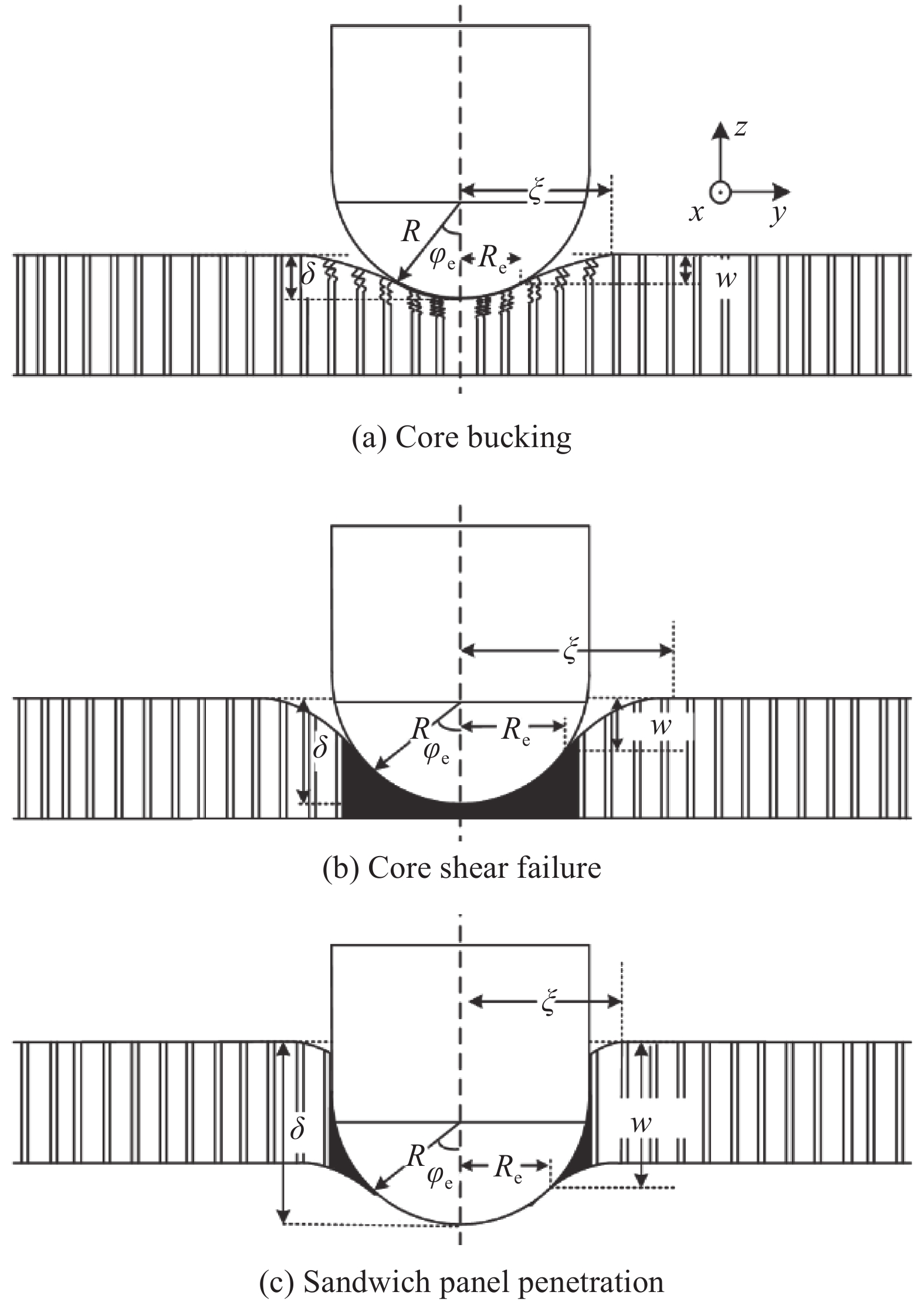
图 5 铝蜂窝夹层板冲击损伤模型
Figure 5. Impact damage model of aluminum honeycomb sandwich panels
R—Punch radius; \xi —Indentation deformation radius of the aluminum honeycomb sandwich panels by impact; \delta —Damage depth caused by the punch; {R}_{\mathrm{e}} —Contact radius between the punch and the top or back facesheets; {\varphi }_{\mathrm{e}} —Angle between the contact radius position and the center line of the punch; w —Lateral displacement of the aluminum honeycomb sandwich panels at the contact radius
表 1 冲击试验工况
Table 1 Experimental conditions
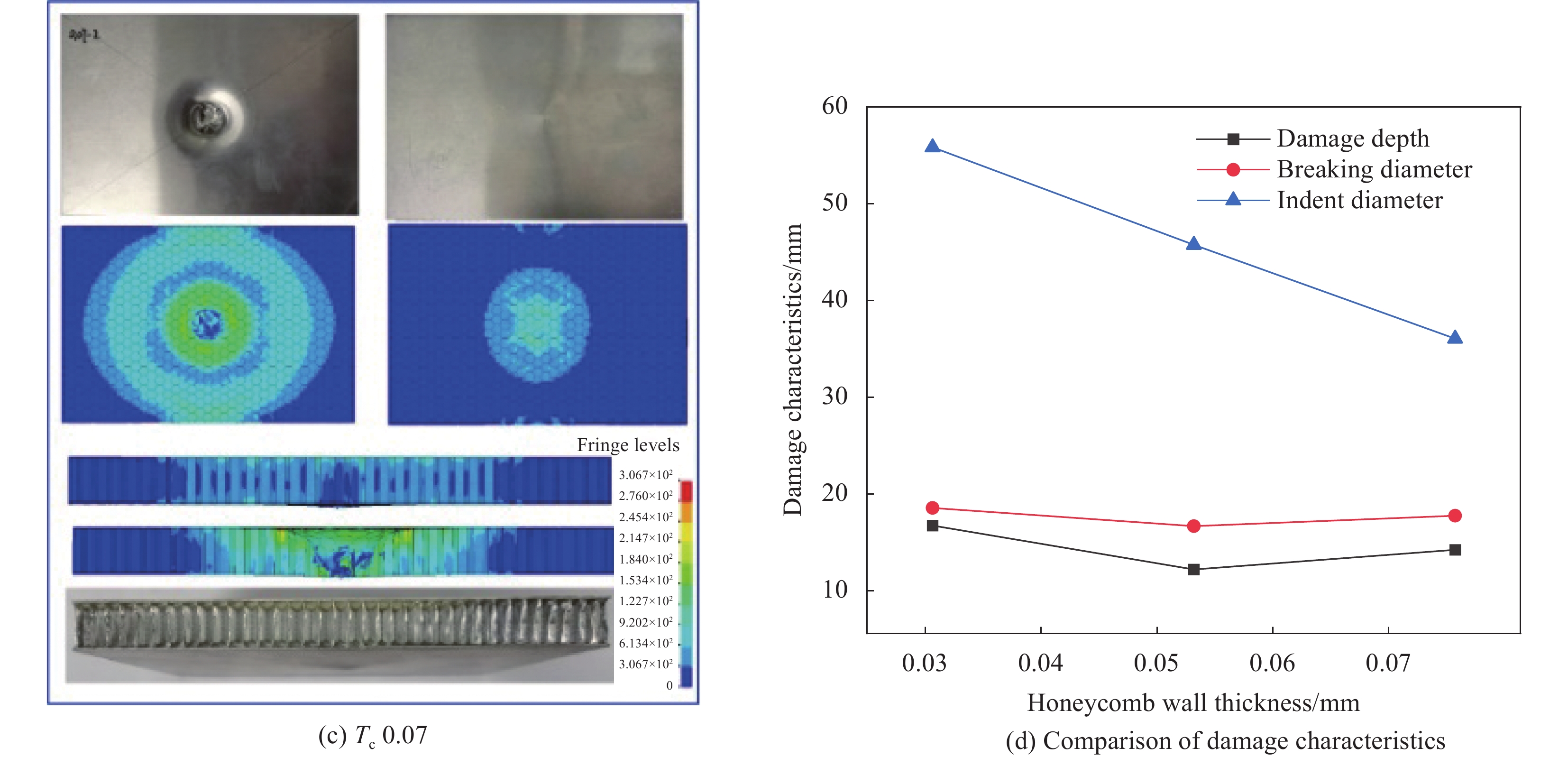
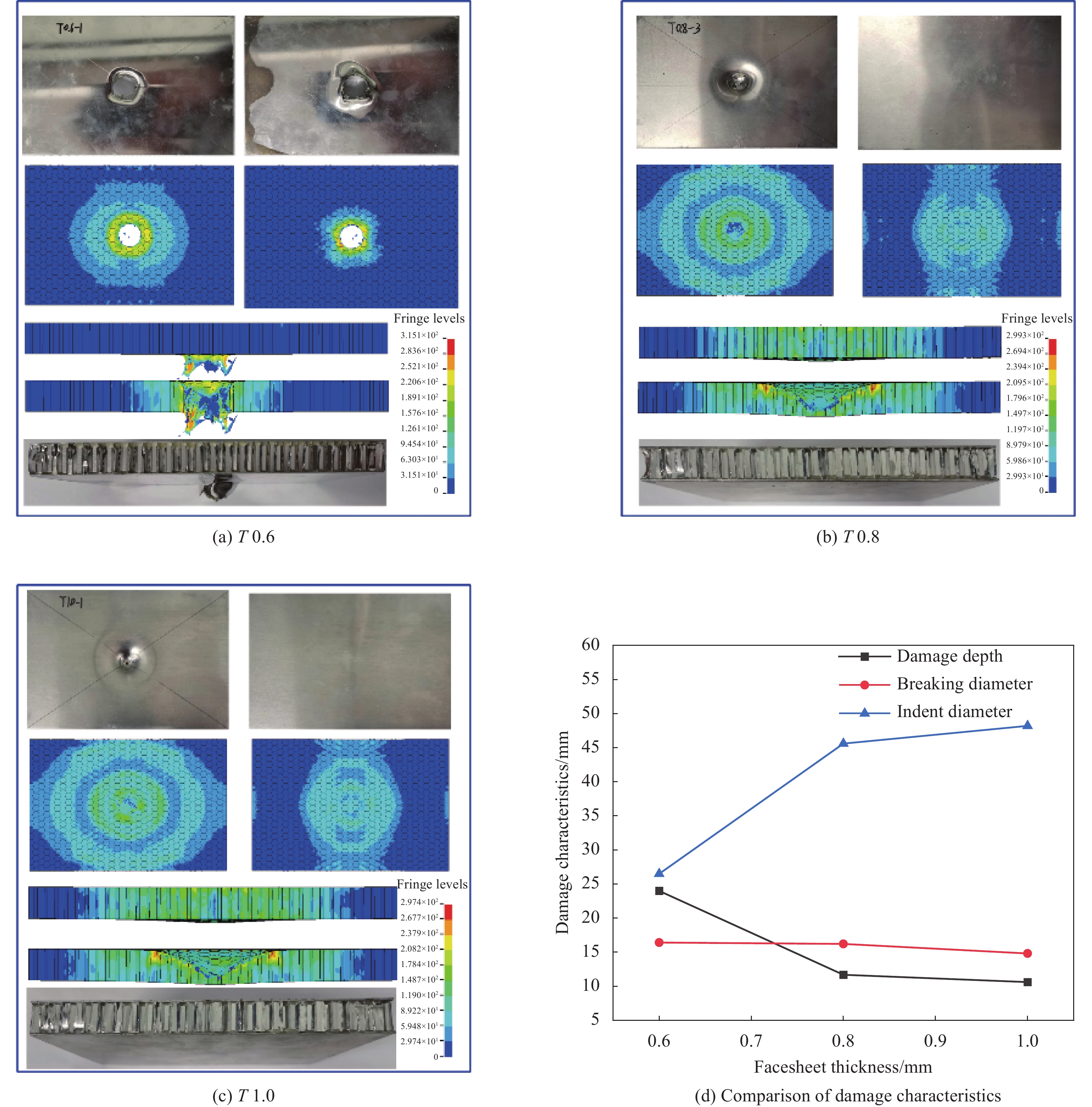
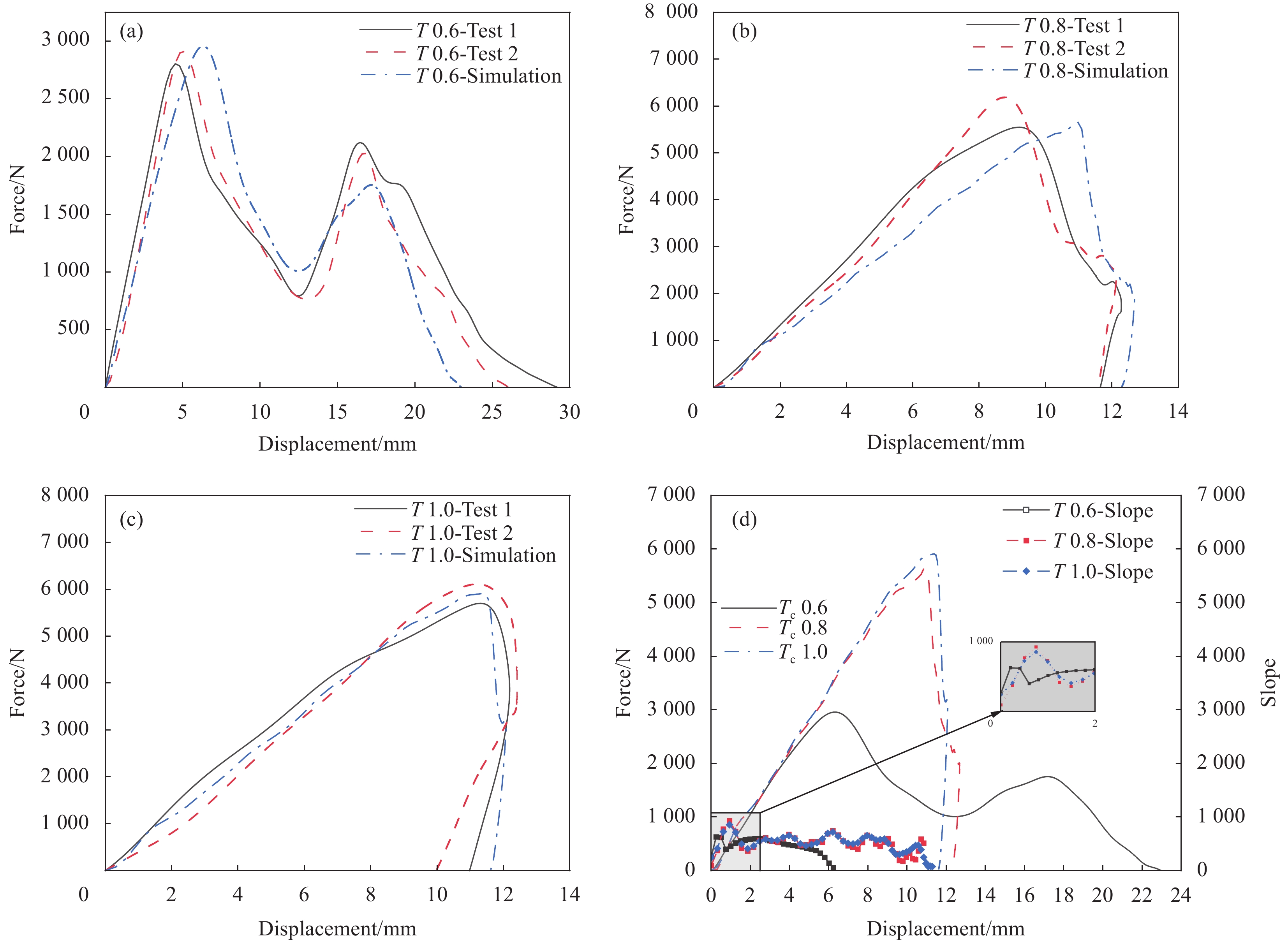
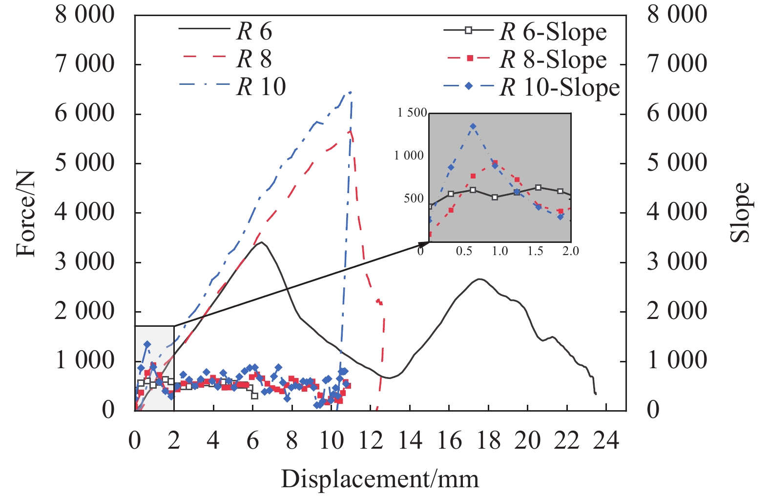
Variable Test label Honeycomb cell diameter D/mm Honeycomb wall thickness {T}_{\mathrm{c}} /mm Facesheet thickness T /mm Punch radius
R/mmHoneycomb cell diameter D 3.2 3.2 0.05 0.8 8 D 4.8 4.8 0.05 0.8 8 D 6.4 6.4 0.05 0.8 8 Honeycomb wall thickness {T}_{\mathrm{c}} 0.03 4.8 0.03 0.8 8 {T}_{\mathrm{c}} 0.05 4.8 0.05 0.8 8 {T}_{\mathrm{c}} 0.07 4.8 0.07 0.8 8 Facesheet thickness T 0.6 4.8 0.05 0.6 8 T 0.8 4.8 0.05 0.8 8 T 1.0 4.8 0.05 1.0 8 Punch radius R 6 4.8 0.05 0.8 6 R 8 4.8 0.05 0.8 8 R 10 4.8 0.05 0.8 10 表 2 铝合金材料参数
Table 2 Aluminum alloy parameters
Aluminum alloy grade Density/(kg·m−3) Young's modulus/GPa Poisson's ratio A B C n 5052 2685 70 0.33 138 231 0.015 0.63 3003 2740 69 0.33 214 143 0.015 0.36 Note: A, B, C, n—Material dependent constants of Johnson-Cook model. 表 3 环氧胶层性能参数
Table 3 Epoxy adhesive layer performance parameters
{E}_{\mathrm{N}} /mm3 {E}_{\mathrm{T}} /mm3 {G}_{\mathrm{I}}^{\mathrm{C}} /mm {G}_{\mathrm{I}\mathrm{I}}^{\mathrm{C}} /mm {\sigma }_{\mathrm{I}}^{\mathrm{m}\mathrm{a}\mathrm{x}} /MPa {\sigma }_{\mathrm{I}\mathrm{I}}^{\mathrm{m}\mathrm{a}\mathrm{x}} /MPa 1×10⁵ 1×10⁵ 0.26 1.002 30 60 表 4 铝蜂窝夹层板损伤模式汇总
Table 4 Summary of damage modes of aluminum honeycomb sandwich panels
Specimen Core bucking Core shear failure Sandwich panel penetration D 3.2 — — √ D 6.4 — √ — {T}_{\mathrm{c}} 0.03 — √ — {T}_{\mathrm{c}} 0.07 — — √ T 0.6 — — √ T 0.8 — — √ T 1.0 — √ — R 6 — — √ R 10 √ — — 表 5 铝蜂窝夹层板的损伤模式和载荷预测
Table 5 Damage mode and load prediction of aluminum honeycomb sandwich panels
Damage mode Threshold load Qualitative damage conditions Core bucking {P}_{\mathrm{c}\mathrm{o}\mathrm{r}\mathrm{e}}^{\mathrm{b}\mathrm{u}\mathrm{c}\mathrm{k}\mathrm{i}\mathrm{n}\mathrm{g}}=3\sqrt{3}{\sigma }_{\mathrm{c}}\left(1+\sqrt{3}\dfrac{D}{R}\right){\left(\dfrac{2{D}_{\mathrm{f}}}{{E}_{3\mathrm{c}}}\right)}^{\frac{2}{3}} Honeycomb core strength ↑
Facesheet strength ↑
Punch radius ↑Core shear failure {P}_{\mathrm{c}\mathrm{o}\mathrm{r}\mathrm{e}}^{\mathrm{s}\mathrm{h}\mathrm{e}\mathrm{a}\mathrm{r}}=72\dfrac{{A}_{1}^{2}{\gamma }_{\mathrm{f}}^{6}}{{\sigma }_{\mathrm{c}\mathrm{r}}}+{\text{π}}{\sigma }_{\mathrm{c}\mathrm{r}}{R}_{\mathrm{e}}^{2} Honeycomb core strength ↓
Facesheet strength ↑
Punch radius ↑Sandwich panel penetration {P}_{\mathrm{f}}^{\mathrm{c}\mathrm{r}\mathrm{a}\mathrm{c}\mathrm{k}\mathrm{i}\mathrm{n}\mathrm{g}}=2{\text{π}}{R}_{\mathrm{e}}{A}_{1}\sqrt{2{\varepsilon }_{\mathrm{r}}}+{\text{π}}{q}_{\mathrm{c}}{\xi }^{2} Honeycomb core strength ↑
Facesheet strength ↓
Punch radius ↓Notes: P_{\text {core }}^{\text {bucking }} —Peak load of the buckling mode of the Core bucking; σc—Equivalent compressive strength in the out-of-plane direction of the honeycomb core; D—Honeycomb cell diameter; R—Punch radius; Df—Facesheet bending stiffness; E3c—Equivalent Young's modulus of the honeycomb core; \mathrm{P}_{\text {core }}^{\text {shear }} —Peak load of Core shear failure model; A1—Facesheet membrane stiffness; γc—Transverse shear strain of honeycomb core; σcr—Honeycomb compressive strength considering punch diameter; Re—Contact radius between the punch and the sandwich panel; P_{\mathrm{f}}^{\text {cracking }} —Peak load of the Sandwich panel penetration model; εr—Facesheet membrane strain; ξ—Indentation deformation radius of the aluminum honeycomb sandwich panels by impact. -
[1] SUN M Q, WOWK D, MECHEFSKE C, et al. Surface and honeycomb core damage in adhesively bonded aluminum sandwich panels subjected to low-velocity impact[J]. Composites Part B: Engineering,2022,230:109506. DOI: 10.1016/j.compositesb.2021.109506
[2] ZHANG J X, ZHU Y Q, LI K K, et al. Dynamic response of sandwich plates with GLARE face-sheets and honeycomb core under metal foam projectile impact: Experimental and numerical investigations[J]. International Journal of Impact Engineering,2022,164:104201. DOI: 10.1016/j.ijimpeng.2022.104201
[3] IVAÑEZ I, MOURE M M, GARCIA S K, et al. The oblique impact response of composite sandwich plates[J]. Composite Structures,2015,133:1127-1136. DOI: 10.1016/j.compstruct.2015.08.035
[4] WANG S Y, XU Y X, ZHANG X G, et al. Design and fabrication of aluminum honeycomb sandwich structures by atmosphere protect brazing: Microstructural evolution and mechanical behavior[J]. Materialia,2022,22:101423. DOI: 10.1016/j.mtla.2022.101423
[5] WANG H R, LONG S C, YAO X H, et al. Analytical study on the low-velocity impact penetration of the fully-clamped foam-core composite sandwich panels[J]. Composites Part B: Engineering,2021,224:109214. DOI: 10.1016/j.compositesb.2021.109214
[6] ZHANG D H, JIANG D, FEI Q G, et al. Experimental and numerical investigation on indentation and energy absorption of a honeycomb sandwich panel under low-velocity impact[J]. Finite Elements in Analysis and Design,2016,117-118:21-30. DOI: 10.1016/j.finel.2016.04.003
[7] SAFRI S N A, SULTAN M T H, YIDRIS N, et al. Low velocity and high velocity impact test on composite materials–A review[J]. The International Journal of Engineering and Science,2014,3(9):50-60.
[8] WU Y H, LIU Q, FU J, et al. Dynamic crash responses of bio-inspired aluminum honeycomb sandwich structures with CFRP panels[J]. Composites Part B: Engineering,2017,121:122-133. DOI: 10.1016/j.compositesb.2017.03.030
[9] HE W T, YAO L, MENG X J, et al. Effect of structural parameters on low-velocity impact behavior of aluminum honeycomb sandwich structures with CFRP face sheets[J]. Thin-Walled Structures,2019,137:411-432. DOI: 10.1016/j.tws.2019.01.022
[10] 齐佳旗, 段玥晨, 铁瑛, 等. 结构参数对CFRP蒙皮-铝蜂窝夹层板低速冲击性能的影响[J]. 复合材料学报, 2020, 37(6):1352-1363. QI Jiaqi, DUAN Yuechen, TIE Ying, et al. Influence of structural parameters on low-velocity impact performance of CFRP skin-aluminum honeycomb sandwich panels[J]. Acta Materiae Compositae Sinica,2020,37(6):1352-1363(in Chinese).
[11] SUN G Y, HUO X T, WANG H X, et al. On the structural parameters of honeycomb-core sandwich panels against low-velocity impact[J]. Composites Part B: Engineering,2021,2016:108881.
[12] ZHU S Q, CHAI G B. Damage and failure mode maps of composite sandwich panel subjected to quasi-static indentation and low velocity impact[J]. Composite Structures,2013,101:204-214. DOI: 10.1016/j.compstruct.2013.02.010
[13] EBRAHIMI H, GHOSH R, MAHDI E, et al. Honeycomb sandwich panels subjected to combined shock and projectile impact[J]. International Journal of Impact Engineering,2016,95:1-11. DOI: 10.1016/j.ijimpeng.2016.04.009
[14] SABAH S H A, KUEH A B H, BUNNORI N M. Failure mode maps of bio-inspired sandwich beams under repeated low-velocity impact[J]. Composites Science and Technology,2019,182:107785. DOI: 10.1016/j.compscitech.2019.107785
[15] ZHANG Y W, YAN L L, ZHANG C, et al. Low-velocity impact response of tube-reinforced honeycomb sandwich structure[J]. Thin-Walled Structures,2021,158:107188. DOI: 10.1016/j.tws.2020.107188
[16] LIU J F, CHEN W S, HAO H, et al. Numerical study of low-speed impact response of sandwich panel with tube filled honeycomb core[J]. Composite Structures,2019,220:736-748. DOI: 10.1016/j.compstruct.2019.04.023
[17] PALOMBA G, EPASTO G, CRUPI V, et al. Single and double-layer honeycomb sandwich panels under impact loading[J]. International Journal of Impact Engineering,2018,121:77-90. DOI: 10.1016/j.ijimpeng.2018.07.013
[18] WANG Z G, WANG X X, LIU K, et al. Crash worthiness index of honeycomb sandwich structures under low-speed oblique impact[J]. International Journal of Mechanical Sciences,2021,208:106683. DOI: 10.1016/j.ijmecsci.2021.106683
[19] ASTM. Standard test method for measuring the damage resistance of a fiber-reinforced polymer matrix composite to a drop-weight impact event: ASTM D7136/D7136 M-2015[S]. West Conshohocken: ASTM International, 2015.
[20] JOHNSON G R, COOK W H. A constitutive model and data for metals subjected to large strains, high strain rates and high temperatures[C]//In: Proceedings of the Seventh International Symposium on Ballistics. Hague: Scientific Research Publishing, 1983: 541-547.
[21] SUN G Y, CHEN D D, WANG H X, et al. High-velocity impact behaviour of aluminium honeycomb sandwich panels with different structural configurations[J]. International Journal of Impact Engineering,2018,122:119-136. DOI: 10.1016/j.ijimpeng.2018.08.007
[22] MUFLAHI S A, MOHAMED G F A, HALLETT S R. Investigation of delamination modeling capabilities for thin composite structures in LS-DYNA[C]//13th International LS-DYNA Users Conference. Dearborn: Bristol University Press, 2014: 1-14.
[23] RAJU K S, SMITH B L, TOMBLIN J S, et al. Impact damage resistance and tolerance of honeycomb core sandwich panels[J]. Journal of Composite Materials,2008,42(4):385-412. DOI: 10.1177/0021998307088596
[24] RAJU K S, TOMBLIN J S. Damage characteristics in sandwich panels subjected to static indentation using spherical indentors[C]//19th AIAA Applied Aerodynamics. Anaheim: American Institute of Aeronautics and Astronautics, 2001: 103-111.
[25] BERNARD M L, LAGACE P A. Impact resistance of composite sandwich pates[J]. Journal of Reinforced Plastics and Composites,1989,8(5):432-445. DOI: 10.1177/073168448900800502
[26] SCHUBEL P M, LUO J J, DANIEL I M. Impact and post impact behavior of composite sandwich panels[J]. Composites Part A: Applied Science and Manufacturing,2007,38(3):1051-1057. DOI: 10.1016/j.compositesa.2006.06.022
[27] KIM J K, YU T X. Indentation, penetration and perforation of composite laminate and sandwich panels under quasi-static and projectile loading[J]. Key Engineering Materials,1998,141(143):501-552.
[28] PETRAS A, SUTCLIFFE M P F. Failure mode maps for honeycomb sandwich panels[J]. Composite Structures,1999,44:237-252. DOI: 10.1016/S0263-8223(98)00123-8
[29] ZHU F, LU G, RUAN D, et al. Plastic deformation, failure and energy absorption of sandwich structures with metallic cellular cores[J]. International Journal of Protective Structures,2010,1(4):507-541. DOI: 10.1260/2041-4196.1.4.507
[30] CHAI G B, ZHU S. A review of low-velocity impact on sandwich structures[J]. Proceedings of the Institution of Mechanical Engineers, Part L: Journal of Materials: Design and Applications,2011,225(4):207-230. DOI: 10.1177/1464420711409985
[31] LEE S M, TSOTSIS T K. Indentation failure behavior of honeycomb sandwich panels[J]. Composites Science and Technology,2000,60(8):1147-1159. DOI: 10.1016/S0266-3538(00)00023-3
[32] OLSSON R. Engineering method for prediction of impact response and damage in sandwich panels[J]. Journal of Sandwich Structures & Materials,2002,4:3-19.
[33] CHATURVEDI R, TRIKHA M, SIMHA K R Y. Impact penetration through spacecraft honeycomb panels analytical, numerical and experimental study[J]. Materials Today: Proceedings,2020,21(2):1050-1058.
[34] WIERZBICKI T, ALVAREZ A L, FATT M H. Impact energy absorption of sandwich plates with crushable core[C]//In: Proceedings of the ASME/AMD Symposium, Impact Waves, and Fracture. Los Angeles: U.S. Department of Energy Office of Scientific and Technical Information, 1995, 205: 391-411.
[35] ZHOU G, HILL M, LOUGHLAN J. Damage characteristics of composite honeycomb sandwich panels in bending under quasi-static loading[J]. Journal of Sandwich Structures & Materials,2006,8(1):55-90.
[36] ZHOU G, HILL M. Investigation of parameters governing the damage and energy absorption characteristics of honeycomb sandwich panels[J]. Journal of Sandwich Structures & Materials,2007,9(4):309-342.
[37] ZHOU G, HILL M. Impact damage and energy-absorbing characteristics and residual in-plane compressive strength of honeycomb sandwich panels[J]. Journal of Sandwich Structures & Materials,2009,11(4):329-356.
[38] FATT M S H, PARK K S. Dynamic models for low-velocity impact damage of composite sandwich panels–Part B: Damage initiation[J]. Composite Structures,2001,52(3-4):353-364. DOI: 10.1016/S0263-8223(01)00045-9
[39] LEE Y W, WOERTZ J C, WIERZBICKI T. Fracture prediction of thin plates under hemi-spherical punch with calibration and experimental verification[J]. International Journal of Mechanical Sciences,2004,46(5):751-781. DOI: 10.1016/j.ijmecsci.2004.05.004
-
期刊类型引用(7)
1. 梁华霖,宋超,解正坤. 黄药降解类光催化材料制备研究现状. 山西大同大学学报(自然科学版). 2024(06): 105-111 .  百度学术
百度学术
2. 高生旺,赵星鹏,陆迦勒,崔娟,王国英,张青. Ag-BiOBr/WO_3复合材料的制备及强化磺胺异噁唑去除性能. 复合材料学报. 2023(03): 1455-1467 .  本站查看
本站查看
3. 王丽苹,阮玉娴,李仁星,余莹,陈琳,姜帅. Fe-MILs系可见光响应复合材料在光诱导反应中的应用研究进展. 化学通报. 2023(12): 1409-1425 .  百度学术
百度学术
4. 梁锐,李明阳,高翔鹏,于先坤,童雄,龙红明. 选矿废水中残留黄药光催化处理及降解效率改进方式研究进展. 过程工程学报. 2022(01): 1-13 .  百度学术
百度学术
5. 葛奉娟,朱捷,陈艳,徐艳. 制备方法对BiOBr形貌及其可见光降解活性的研究. 能源与环境. 2021(01): 97-99+101 .  百度学术
百度学术
6. 杜春艳,宋佳豪,谭诗杨,阳露,张卓,余关龙. 石墨烯桥联的ZnO/Ag_3PO_4复合材料的制备及其对环丙沙星的降解性能. 复合材料学报. 2021(07): 2254-2264 .  本站查看
本站查看
7. 陈星玉,张雪乔,鲁李李,陈彩霞,向洪瑗,郭梦圆. GQDs/BiOBr复合光催化剂可见光降解磺胺废水的研究. 天然气化工(C1化学与化工). 2021(S1): 74-81 .  百度学术
百度学术
其他类型引用(6)
-




 下载:
下载:


