

Experimental study on the mechanical properties of polypropylene fiber-steel bar reinforced concrete pipe
-
摘要: 顶管施工中钢筋/混凝土管节存在开裂现象,严重影响工程质量与后续营运。鉴于聚丙烯纤维具有改善混凝土抗拉、抗裂性能的作用,本文采用2种聚丙烯细纤维和1种聚丙烯粗纤维,设计了无纤维、单掺粗纤维及混掺三种尺度纤维的3组钢筋/混凝土管试件,进行了三点试验,对比分析管节的开裂破坏形态、荷载挠度曲线和开裂延性指标。并建立纤维混凝土管节三点试验的有限元模型,进一步探究聚丙烯纤维掺量对钢筋/混凝土管节受力性能的影响规律。结果表明,聚丙烯粗纤维可提高混凝土管的抗裂与承载能力,聚丙烯粗、细纤维的协同作用使管达到更高的使用和极限强度。相比无纤维管,混掺多尺度纤维提升管的使用强度和极限强度分别为28.7%和36.4%。此外,数值模拟合理地预测了纤维/混凝土管节的荷载挠度响应,并针对混凝土管节的极限强度值,得到单掺和混掺聚丙烯纤维时粗纤维的最佳掺量。Abstract: The cracking of reinforced concrete pipe during pipe jacking construction seriously affects the project quality and subsequent operation. In view of the role of polypropylene fiber in improving the crack resistance and tensile properties of concrete, this paper adopted two types of fine polypropylene fibers and one type of crude polypropylene fiber, designing 3 groups of reinforced concrete pipe specimens, which were reinforced with plain concrete, single-scale crude fiber and hybrid three-scale fibers. The three-edge-bearing test was carried out. The cracking failure patterns, load-deflection responses and ductility indexes after cracking of these pipes were comparatively analyzed. A finite element numerical model was developed for reproducing the three-edge-bearing test to investigate the influence law of polypropylene fiber content on the mechanical properties of reinforced concrete pipe. The results show that the crack resistance and load-bearing capacities of concrete pipe are improved by adding crude polypropylene fiber, and the higher service and ultimate strength of pipe are achieved under the synergistic action of fine and crude polypropylene fibers. Compared with the pipe without fiber, the hybrid multi-scale fibers increase the service and ultimate strength by 28.7% and 36.4%. In addition, using this numerical simulation method, the load-deflection responses of fiber reinforced concrete pipe can be reasonably predicted, and the optimum contents of crude fiber when incorporating single-scale and three-scale fibers are obtained, aiming to the higher ultimate strength of concrete pipe.
-
钢筋/混凝土是国内外顶管工程中使用较多的管材[1]。混凝土作为生产该类管的主要材料,由于其抗拉强度低、韧性差,使管节在受到顶推作用、土体挤压后易产生裂缝,加快了钢筋锈蚀和管结构恶化,降低工程的使用寿命。虽然利用钢筋抗剪加固可一定程度地控制钢筋/混凝土管节开裂,但并非是解决混凝土表面微裂缝的理想方案[2]。已有研究[3-5]证明在混凝土管中加入钢纤维和合成纤维是加强管节裂缝控制的有效措施。但是钢纤维易受到氯化物环境腐蚀,相比而言,合成纤维成为一种更理想的混凝土管增强纤维,其中聚丙烯纤维价格低廉、耐腐蚀性好、稳定性高被较早推广,而且聚丙烯纤维在提高混凝土的韧性和开裂后残余强度方面甚至比钢纤维性能更优[6]。
按照纤维直径大小,可将聚丙烯纤维分为聚丙烯细纤维(直径不大于0.1 mm)和聚丙烯粗纤维(直径大于0.1 mm)即塑钢纤维。Wilson等[7]采用三点试验法初步研究了375~900 mm七种内径混凝土管在不同聚丙烯粗纤维纤维含量下的荷载-位移曲线和破坏裂缝模式,表明随着纤维含量的增加管节峰值强度提高,而且不同管径下存在相应的最佳掺量范围。Rikabi等[8]分析单掺9 kg/m3聚丙烯粗纤维对钢筋/混凝土管节极限强度、刚度和变形能力的影响,指出加入纤维可以减少管壁厚度和钢筋用量,提高管节韧性的同时降低生产运输成本。为充分发挥不同纤维的增强加固作用,已有学者提出将钢纤维与合成纤维混杂掺入混凝土管中。Perk等[9]研究表明混掺钢-聚丙烯纤维在提高混凝土管强度、延性和抗裂方面比单掺纤维增强材料(钢纤维或聚丙烯纤维)更显著。但是仍然面临着钢纤维易被腐蚀的缺点,有必要采用其他纤维代替钢纤维与聚丙烯纤维进行混掺,在获得良好抗拉[10]和抗裂[11]效果的同时又提高混凝土管的耐久性。其中,罗洪林等[12]指出聚丙烯粗纤维和细纤维增强混凝土抗拉性能的机制不尽相同、各有优势;而且混掺多种尺度的聚丙烯纤维能够有效阻止混凝土的塑性开裂,限制早期和后期裂缝发展[13]。然而目前关于多尺度聚丙烯纤维对钢筋/混凝土管的作用方面鲜有研究。
鉴于此,本文开展单掺聚丙烯粗纤维和混掺三种尺度聚丙烯纤维的钢筋/混凝土管节三点试验,建立管节三点试验的有限元模型,分析管节破坏形态、载荷-挠度曲线和能量吸收能力,研究单掺和混掺下聚丙烯粗纤维含量对混凝土管承载力和延性的影响规律。
1. 试验材料与方法
1.1 原材料及配合比
试验所采用的聚丙烯纤维外观如图1所示,其中聚丙烯细纤维分为FPF1与FPF2两种,呈直型束丝状;聚丙烯粗纤维为CPF,呈波纹型单根状。其物理和力学性能指标见表1,推荐单掺量[14]中聚丙烯细纤维为0.9 kg/m3,聚丙烯粗纤维为6.0 kg/m3。为确保聚丙烯纤维在混凝土中的均匀分散不成团,混凝土采用先掺法搅拌[14]。试验混凝土的强度等级设计为C50,其中普通硅酸盐水泥强度为52.5R,粗骨料采用粒径大小分别为10~20 mm和5~10 mm的碎石块,细骨料采用0.15~5 mm粒径的天然砂,并添加1%水泥含量的聚羧酸高效减水剂以提高混凝土成型性能。混凝土设计配合比如表2所示。
表 1 不同尺度聚丙烯纤维的物理力学性能Table 1. Physical and mechanical properties of polypropylene fibers of different scalesFiber code Diameter/mm Length/mm Aspect ratio Tensile
strength/MPaElasticity
modulus/GPaDensity/
(kg·m−3)Recommended single
dosage/(kg·m−3)FPF1 0.026 19 730.8 641 8.5 0.91 0.9 FPF2 0.1 19 190 322 3.9 0.91 0.9 CPF 0.8 50 62.5 706 7.4 0.95 6.0 Notes: FPF1—Type of fine polypropylene fiber; FPF2—Another type of fine polypropylene fiber; CPF—Crude polypropylene fiber. 表 2 C50混凝土设计配合比Table 2. Design mix ratio of C50 concreteMaterial Cement Coarse aggregate Sand Water Water reducer 10-20 mm 5-10 mm Dosage/(kg·m−3) 375 545 545 850 135 3.75 1.2 管节试件设计
根据多尺度聚丙烯纤维混凝土基本拉压性能的研究成果[13, 15],采用对混凝土抗拉和抗裂提升较高的聚丙烯纤维组合,针对同一尺寸和配筋率的钢筋/混凝土管节,最终确定试验试件的纤维组数为三类(见表3),其他聚丙烯纤维掺量组合通过数值模拟实现。
其中,S/C试件由普通混凝土浇筑,作为基准参照的标准管节;CPF-S/C为单掺聚丙烯粗纤维CPF的管节,纤维掺量为6.0 kg/m3;FPF1-FPF2-CPF-S/C为混掺粗细三种聚丙烯纤维的管节,FPF1、 FPF2、CPF三种纤维的掺量分别为0.6、0.6、4.8 kg/m3。管节截面尺寸和配筋形式如图2所示,其内、外直径分别为1 000 mm和1 200 mm,长度1 m,外层混凝土保护层厚度为27 mm,内层厚度为20 mm,环向配筋率为1%,非螺旋配筋。
表 3 试验各组不同尺度聚丙烯纤维的配比Table 3. Proportions of polypropylene fibers of different scales in each specimenkg·m−3 Pipe code Fine polypropylene fibers Crude polypropylene fiber Total content FPF1 FPF2 CPF S/C 0 0 0 0 CPF-S/C 0 0 6 6 FPF1-FPF2-CPF-S/C 0.6 0.6 4.8 6 Notes: S/C—Reinforced concrete pipe without fiber; CPF-S/C—Reinforced concrete pipe with crude polypropylene fiber; FPF1-FPF2-CPF-S/C—Reinforced concrete pipe with multi-scale polypropylene fibers. ![]() 图 2 钢筋/混凝土管节试件截面与配筋Figure 2. Section and reinforcement of reinforced concrete pipe specimen
图 2 钢筋/混凝土管节试件截面与配筋Figure 2. Section and reinforcement of reinforced concrete pipe specimen![]() 图 3 三点试验加载装置示意图Figure 3. Schematic diagram of the pipe three-edge-bearing test loading device
图 3 三点试验加载装置示意图Figure 3. Schematic diagram of the pipe three-edge-bearing test loading device1.3 三点试验过程
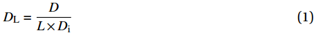
三点试验法是测试钢筋/混凝土排水管外压荷载的标准方法[16],通过在管顶径向施压,测定钢筋/混凝土管产生0.3 mm裂缝宽度对应的荷载及峰值荷载,确定管节所属强度等级。本试验加载装置如图3所示,主要由试验机架、加荷与显示量值的系统及位移传感器等组成。
在三点试验中,管底部支撑于两硬木支承梁上,支承梁净距取100 mm,各截面尺寸为80 mm×100 mm,并且支承梁与管节接触处制成半径12.5 mm的圆弧;管的顶部设置橡胶垫板与加载钢梁,橡胶垫板截面尺寸为25 mm×120 mm,以使荷载均匀地作用在试验管上。在ASTM C76[17]中规定了关于钢筋/混凝土管节的评价标准,管的支承强度采用D-load (DL)值表征,即单位长度与内径下管所承受的荷载,计算公式如下:
DL=DL×Di (1) 其中:D为管顶承受的集中荷载(N);L为管节长度(m);Di为管节内径(mm)。各强度值对应的管节等级如表4所示,表中D-load0.3(D0.3)指的是当裂缝宽度为0.3 mm时的荷载值,即管节的使用强度;D-loadu(Du)指的是最大荷载值,即管节的极限强度。文中试验设计的混凝土管等级为V级,其使用和极限强度应分别达到140 N/m/mm与175 N/m/mm。
![]() 图 4 钢筋/混凝土管节三点试验加载与记录的过程Figure 4. Test process of loading and recording of reinforced concrete pipe three-edge-bearing test表 4 基于ASTM C76[17]的钢筋/混凝土管节等级强度要求Table 4. Grade strength requirements for reinforced concrete pipe based on ASTM C76[17]
图 4 钢筋/混凝土管节三点试验加载与记录的过程Figure 4. Test process of loading and recording of reinforced concrete pipe three-edge-bearing test表 4 基于ASTM C76[17]的钢筋/混凝土管节等级强度要求Table 4. Grade strength requirements for reinforced concrete pipe based on ASTM C76[17]Concrete pipe class D-load(DL)/(N·m−1·mm−1) D-load0.3(D0.3) D-loadu(Du) I 40 60 II 50 75 III 65 100 IV 100 150 V 140 175 Notes: D-load(DL)—Supporting load value of pipe; D-load0.3(D0.3)—Load value when crack width is 0.3 mm, namely service strength; D-loadu(Du)—Maximum load value, namely ultimate strength. 管节三点试验过程参考GB/T 16752—2017[16]和ASTM C497[18]中的相关条文执行,采用单向逐级加载,分成三个阶段控制。第一阶段保持加荷速度为1.8 kN/m/s,直至荷载达到使用强度的75% (即105 N/m/mm);此后在第二阶段将加荷速度降为0.7 kN/m/s,直至荷载达到管的极限强度;当荷载超过极限强度后,第三阶段采用位移控制方法对试件施加竖向位移,加载速率为2 mm/min。在整个试验过程中,加载设备采用微机控制电液伺服压剪试验机,通过计算机的数据采集系统记录和控制三点试验的加载量;并采用东华DH3816N数据采集仪量测顶部挠度、记录钢筋、混凝土的应变数据;使用综合裂纹测试仪监测管节顶部、底部及两侧的裂纹宽度,并实时对裂缝标记编号,检查管节是否出现局部破坏或发生不适合继续承载的变形,部分试验过程如图4所示。
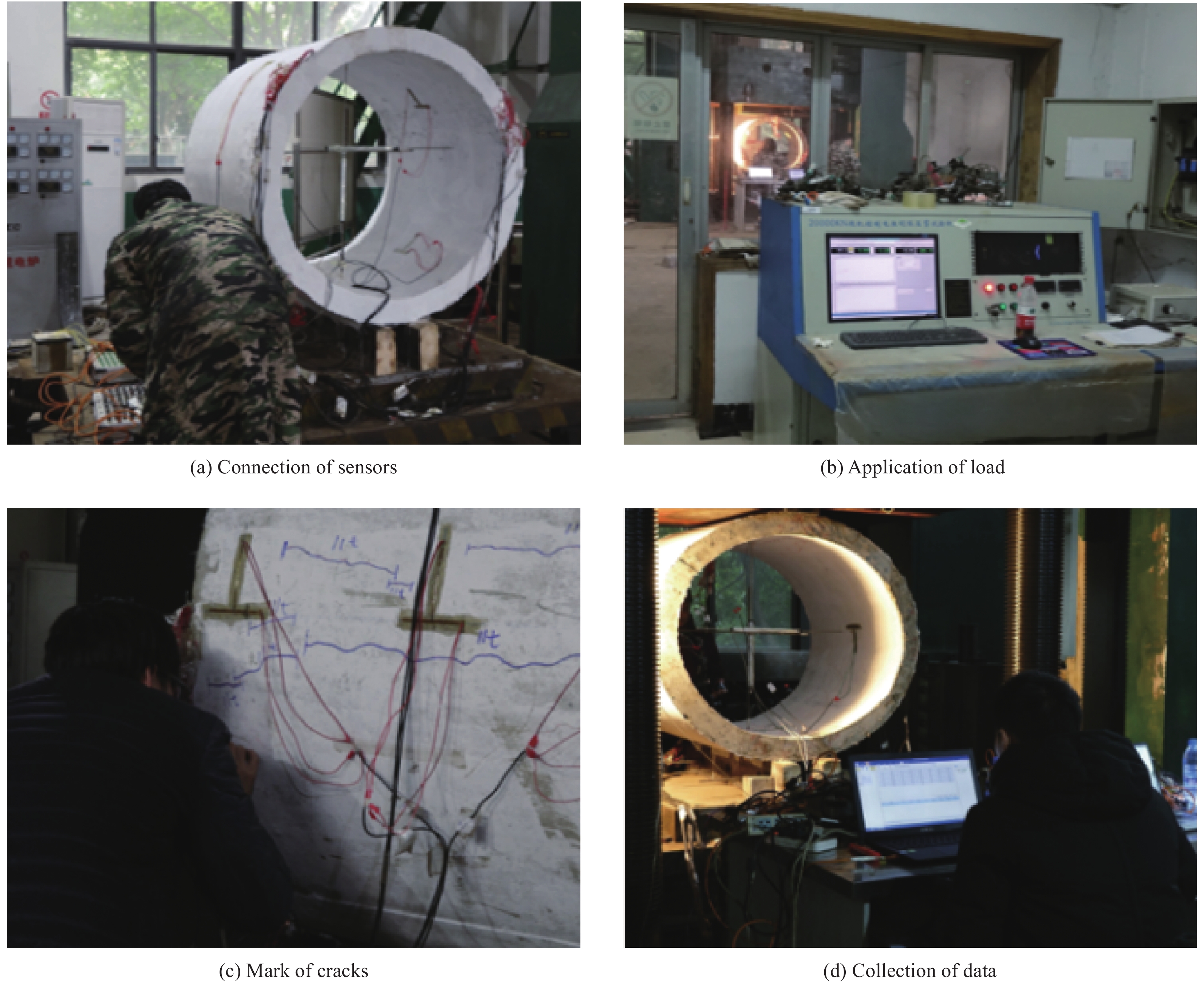
![]() 图 5 三类钢筋/混凝土试验管的开裂破坏形态Figure 5. Cracking and failure modes of three types of test reinforced concrete pipes
图 5 三类钢筋/混凝土试验管的开裂破坏形态Figure 5. Cracking and failure modes of three types of test reinforced concrete pipes2. 试验结果与分析
2.1 钢筋/混凝土管开裂破坏形态
试验管在加载的过程中,由于管顶部和底部混凝土为内壁受拉,而管两侧混凝土为外壁受拉,而且分析表明顶部承担弯矩作用较两侧大[19],因此三类管均表现为在管节顶部内壁首先出现弯曲裂缝,且第一条观测裂缝出现的DL值约为75~85 N/m/mm。随着荷载的持续增加,顶部内壁裂缝沿管径向和轴向延伸,管节底部内壁和两侧外壁的混凝土亦产生裂缝并逐渐发展增多,最终在该四个区域形成较大的贯通主裂缝,混凝土管压溃进而破坏,表现出较明显的弯曲破坏特征,三类试验管的开裂破坏形态如图5所示。对比分析S/C、CPF-S/C与FPF1-FPF2-CPF-S/C的破坏形态,在顶部和底部区域,S/C组试件较CPF-S/C和FPF1-FPF2-CPF-S/C组产生的裂缝更早、宽度更大,裂缝分布更集中,而且管破坏时混凝土剥落掉块现象更严重。CPF-S/C与FPF1-FPF2-CPF-S/C组试件顶部内壁存在多缝开裂现象(如图5(b)、图5(c)所示),在裂缝发展时,掺入的纤维既可以继续承载,同时又可使混凝土基体在其他截面再次交替开裂。在两侧区域,可以明显观察到CPF-S/C与FPF1-FPF2-CPF-S/C试件的裂缝中存在聚丙烯粗纤维的桥接现象,不少纤维被拔出或拉断,说明掺入聚丙烯纤维不仅能抑制管节宏观裂缝的发展,而且有效限制混凝土剥落。
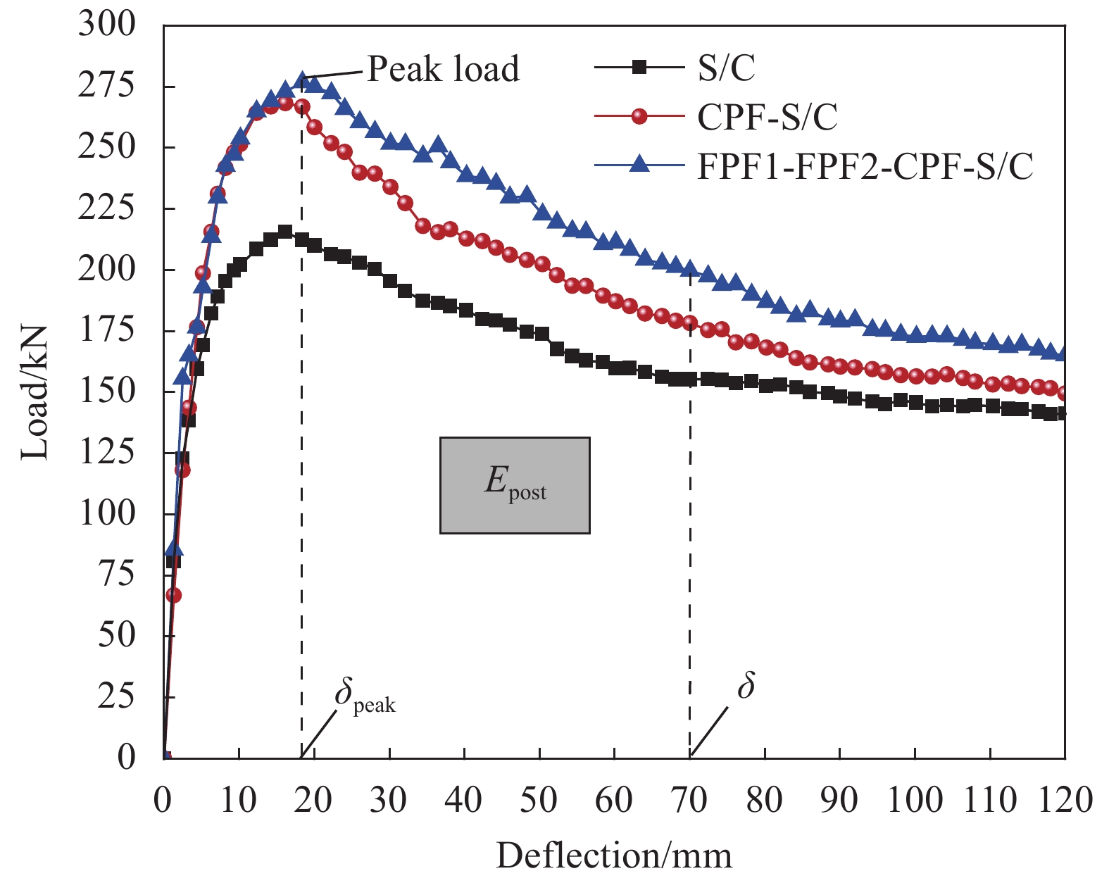
![]() 图 6 钢筋/混凝土管DL与管顶挠度的关系曲线Figure 6. Relation curve between DL and top deflection of reinforced concrete pipes
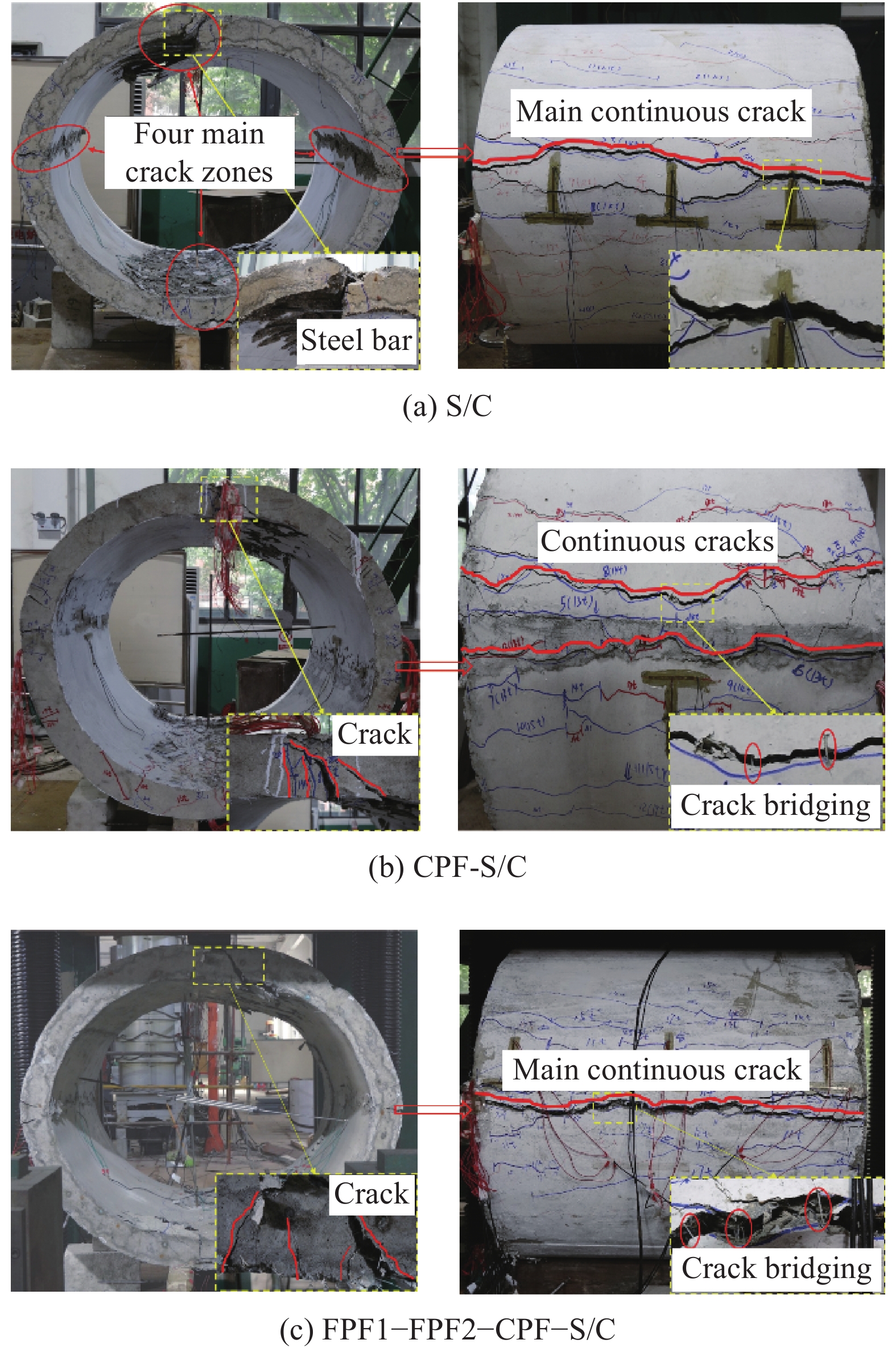
图 6 钢筋/混凝土管DL与管顶挠度的关系曲线Figure 6. Relation curve between DL and top deflection of reinforced concrete pipes2.2 钢筋/混凝土管DL与管顶挠度曲线
各组管的DL值与管顶挠度的关系曲线如图6所示,可见极限强度均高于Ⅴ类管要求。由于钢筋是决定整体强度响应的主要因素,故而S/C、CPF-S/C和FPF1-FPF2-CPF-S/C试件的曲线变化趋势表现得基本一致。加载初期,钢筋与混凝土的应变随荷载呈线性变化,整个管节构件处于弹性阶段,各试验管DL值随挠度呈线性增长;当管顶部混凝土超过其开裂应变后,混凝土产生裂缝,此时粗纤维与钢筋在受拉张力区已发挥作用,使管能够继续受荷直至极限荷载,该阶段荷载挠度曲线仍保持上升趋势;之后挠度继续增加,达到16~19 mm范围后,环向钢筋屈服,试验管达到最大承载力;随后DL值开始下降,试验管进入破坏阶段。但FPF1-FPF2-CPF-S/C和CPF-S/C组管的下降段明显高于S/C组管,FPF1-FPF2-CPF-S/C组亦高于CPF-S/C组,说明混掺聚丙烯粗细纤维能在混凝土管开裂后提供更高的承载能力。
![]() 图 7 计算开裂后强度SPC值的钢筋/混凝土管荷载-挠度曲线Figure 7. Load-deflection curves of reinforced concrete pipes to calculate post-cracking strength SPC valueδ—Deflection; δpeak—Peak deflection corresponding to peak load; Epost—Area bounded by a deflection to peak deflection and a deflection
图 7 计算开裂后强度SPC值的钢筋/混凝土管荷载-挠度曲线Figure 7. Load-deflection curves of reinforced concrete pipes to calculate post-cracking strength SPC valueδ—Deflection; δpeak—Peak deflection corresponding to peak load; Epost—Area bounded by a deflection to peak deflection and a deflection将各试验管的使用强度和极限强度列于表5。单掺聚丙烯粗纤维CPF-S/C组和混掺多尺度聚丙烯纤维FPF1-FPF2-CPF-S/C组及标准S/C组的极限强度分别为270.7、278.5、216.4 N/m/mm,前两组相较于S/C组分别提高了25.1%和28.7%,混凝土管强度得到明显提高。这是由于一方面聚丙烯纤维的抗拉强度高于混凝土基体的抗拉强度,掺入纤维可改善复合基体的抗拉性能;另一方面混凝土产生裂缝后,聚丙烯粗纤维发挥桥接作用,改善了混凝土基体的薄弱受力面。此外,S/C、CPF-S/C、FPF1-FPF2-CPF-S/C组的D0.3分别为126.7、164.8、171.4 N/m/mm,其中S/C组的使用强度未满足Ⅴ类管要求;但与S/C相比,CPF-S/C和FPF1-FPF2-CPF-S/C组的使用强度分别提高了31.1%和36.4%,且均高于140 N/m/mm,满足V级管要求,表明掺入聚丙烯纤维能够改善混凝土管抗裂性能。而且,FPF1-FPF2-CPF-S/C组的D0.3与Du值高出CPF-S/C组约4.0%与2.9%,进一步说明多尺度聚丙烯纤维形成的三维乱向支撑体系,在早期收缩和后期承载过程中发挥了协同作用[20],调整管节裂缝处混凝土的局部应力,控制了裂缝宽度,提高了管强度。
表 5 各钢筋/混凝土试验管节的使用强度与极限强度Table 5. Service load and ultimate load of each reinforced concrete pipesPipe code DL/(N·m−1·mm−1) D0.3 Du S/C 126.7 216.4 CPF-S/C 164.8 270.7 FPF1-FPF2-CPF-S/C 171.4 278.5 2.3 钢筋/混凝土管裂后延性指标
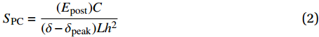
进一步分析纤维对混凝土管延性的影响,结合国内外纤维混凝土管的相关研究[3, 5],采用开裂后强度(Post-cracking strength,SPC)来表征试验管的延性和吸能性能,计算过程如下式所示:
SPC=(Epost)C(δ−δpeak)Lh2 (2) 其中:SPC指某一挠度下的开裂后强度;Epost指在荷载-挠度曲线(图7)中某一挠度至峰值挠度和曲线围成的面积;δ为挠度;δpeak为峰值荷载对应的峰值挠度;C为管节内部周长的一半;L为管节长度;h为管节壁厚。
![]() 图 8 不同挠度下三组钢筋/混凝土管的峰后开裂强度SPCFigure 8. Post-cracking strength SPC at different deflection values for three reinforced concrete pipes
图 8 不同挠度下三组钢筋/混凝土管的峰后开裂强度SPCFigure 8. Post-cracking strength SPC at different deflection values for three reinforced concrete pipes计算SPC所用的荷载-挠度曲线如图7所示。SPC是包含了管节形状尺寸、结构性能如挠度与承载能力等多个指标的综合标准,SPC较高代表管节能量吸收能力较高,延性较好。
图8为三组管在20~120 mm挠度下的SPC值计算结果曲线。可见,在该计算范围内,各管节试件的SPC值随挠度的增大而减小,其变化趋势与荷载-挠度曲线基本一致。在相同挠度δ下,含有纤维的混凝土管表现出更高的开裂后强度。例如在挠度为40 mm时,S/C、CPF-S/C、FPF1-FPF2-CPF-S/C组的开裂后强度分别为31.2、37.3和40.4 N/mm2。而且在同一纤维掺量(6 kg/m3)下,混掺的FPF1-FPF2-CPF-S/C组均体现出更优的SPC值,较CPF-S/C组的提升范围为4.6%~10.0%,表明多种粗细聚丙烯纤维可更好地提高混凝土管的延性和截面内力重分布的能力,而且其改善程度还高于上述对强度的作用,发挥出较好的阻裂增韧效果。
3. 钢筋/混凝土管数值模拟
3.1 有限元模型建立
为进一步探究纤维掺量对混凝土管力学性能的影响情况,采用有限元方法来模拟管三点试验的宏观力学行为[21]。基于通用的数值模拟软件ABAQUS 6.16,建立了上述管节三点试验的有限元模型,如图9所示。模型主要由混凝土管、钢筋笼及上、下部支承梁四部分组成,管的尺寸及配筋率均与前述试验保持一致。其中,上、下部支承梁的截面尺寸分别为25 mm×120 mm和80 mm×100 mm,下部支承梁净距为100 mm。经试算分析不同单元类型与网格尺寸,确定混凝土管与支承梁采用八结点六面体实体非协调单元模拟,钢筋笼采用两结点三维桁架单元模拟,各组件的单元类型与数量如表6所示。此外,在上、下部支承梁与管接触的位置采用绑定作用,钢筋与混凝土管之间采用内置区域相互作用。同时,于下部支承梁底面施加平动约束,上部支承梁顶面施加120 mm位移模拟管径向受压。
![]() 图 9 钢筋/混凝土管节三点试验的有限元数值模型Figure 9. Finite element numerical model for the three-edge-bearing test of reinforced concrete pipeuX, uY, uZ—Displacement values in each direction of X, Y, and Z in the space rectangular coordinate system表 6 钢筋/混凝土管节有限元模型单元类型与数量Table 6. Number and types of the model elements of reinforced concrete pipe
图 9 钢筋/混凝土管节三点试验的有限元数值模型Figure 9. Finite element numerical model for the three-edge-bearing test of reinforced concrete pipeuX, uY, uZ—Displacement values in each direction of X, Y, and Z in the space rectangular coordinate system表 6 钢筋/混凝土管节有限元模型单元类型与数量Table 6. Number and types of the model elements of reinforced concrete pipeModel part Element number Element type Concrete pipe 37 500 C3D8I Lower bearing strips 1 900 Upper bearing strip 600 Steel cage 5 390 T3D2 3.2 模拟材料本构
3.2.1 纤维混凝土本构
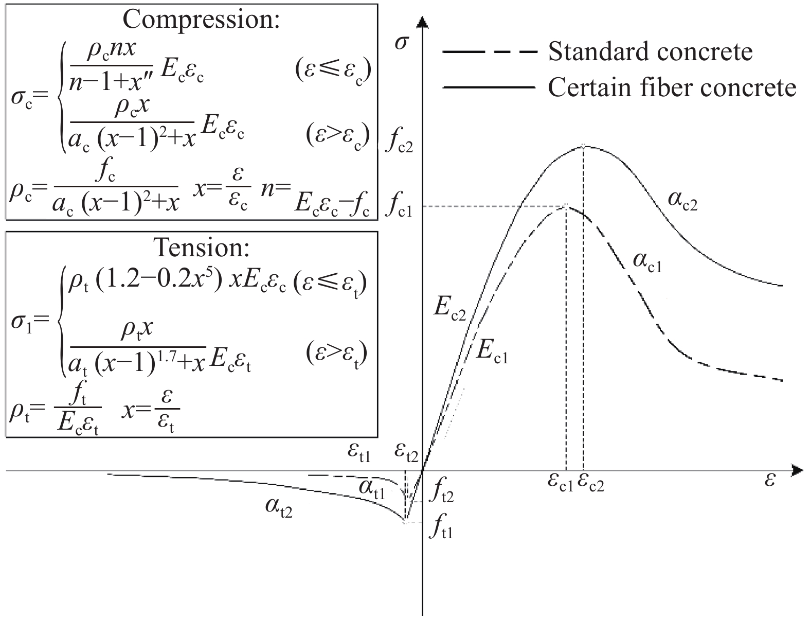
聚丙烯纤维/混凝土的单轴拉压应力-应变关系可采用B 50010—2010[22]提供的本构模型进行拟合[23],如图10所示,主要通过单轴抗拉(抗压)强度ft与fc、峰值拉(压)应变εt与εc、弹性模量Ec、抗拉(抗压)曲线下降段形状参数αt和αc,四类力学指标确定材料的单轴应力-应变曲线和损伤破坏情况。
![]() 图 10 聚丙烯纤维/混凝土单轴拉压应力-应变曲线Figure 10. Uniaxial compressive and tensile stress-strain curves of polypropylene fiber/concretefc, ft—Compressive and tensile strength vaules of concrete; Ec—Elasticity modulus of concrete; αc, αt—Shape parameters of the falling section of the concrete compressive and tensile stress-strain curves; σc and σt—Compressive and tensile stress vaules of concrete; ε—Strain vaule of concrete; ρc, ρt, n and x—Intermediate parameters during the stress calculation process; εc and εt—Compressive and tensile peak strain vaules of concrete
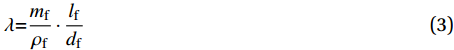
图 10 聚丙烯纤维/混凝土单轴拉压应力-应变曲线Figure 10. Uniaxial compressive and tensile stress-strain curves of polypropylene fiber/concretefc, ft—Compressive and tensile strength vaules of concrete; Ec—Elasticity modulus of concrete; αc, αt—Shape parameters of the falling section of the concrete compressive and tensile stress-strain curves; σc and σt—Compressive and tensile stress vaules of concrete; ε—Strain vaule of concrete; ρc, ρt, n and x—Intermediate parameters during the stress calculation process; εc and εt—Compressive and tensile peak strain vaules of concrete基于试验测得的前述配比下素混凝土的拉压性能参数,参考缪庆旭对多尺度聚丙烯纤维混凝土提出的各个控制指标混杂效应函数W=f (λi,λj,λk)[23],量化聚丙烯纤维对混凝土力学性能的作用,得到纤维混凝土的各项指标值,其中λi、λj、λk分别为3种纤维FPF1、FPF2和CPF的特征值,计算如下:
λ=mfρf⋅lfdf (3) 其中:mf为纤维的质量掺量;ρf为纤维的密度;lf为纤维的长度;df为纤维的当量直径。计算得到三类管试件的混凝土拉压性能指标如表7所示。
表 7 钢筋/混凝土管拉压力学性能指标Table 7. Tensile and compressive mechanical properties indexes of reinforced concrete pipesPipe code λi+λj+λk Ec/MPa fc/MPa εc/10−6 αc ft/MPa εt/10−6 αt S/C 0+0+0 42 500 47.1 2 096 1.94 2.65 142 3 CPF-S/C 0+0+0.39 43 601 52.3 2 607.8 0.31 3.20 165.8 1.38 FPF1-FPF2-CPF-S/C 0.48+0.13+0.32 40 792 56.4 3 018.4 0.12 3.32 224.5 1.40 Note: λi , λj and λk—Eigenvalues of FPF1, FPF2 and CPF. 在ABAQUS软件中,混凝土损伤塑性(Concrete damaged plastic,CDP)模型能够较好地模拟钢筋/混凝土构件在各类加载条件下的非线性力学响应[24],可适用于本次模拟。采用CDP模型时,除输入上述混凝土单轴应力与应变关系外,为确定混凝土的屈服面和塑性流动法则,需定义一组参数,如膨胀角Ψ、流动势偏心率、双轴抗压与单轴抗压的极限强度之比fb0/fc0、应力不变量比K、黏性参数μ,基于相关文献[25]和试算取值如表8所示。
表 8 混凝土损伤塑性模型(CDP)模型的塑性参数取值Table 8. Values of the concrete damaged plastic model (CDP) model plasticity parametersCDP model plasticity parameter Value Dilatation angel Ψ/(°) 36 Flow potential eccentricity 0.1 fb0/fc0 1.16 Stress invariant ratio K 0.67 Viscosity parameter μ 0.0009-0.001 Note: fb0/fc0—Ratio of ultimate strength of biaxial compression to uniaxial compression. 3.2.2 钢筋本构
钢筋采用理想弹塑性本构,钢筋的屈服强度为400 MPa,弹性模量为200 GPa,泊松比为0.3。上下部支承梁采用刚性材料模拟。
3.3 模型结果验证
3.3.1 破坏形态对比
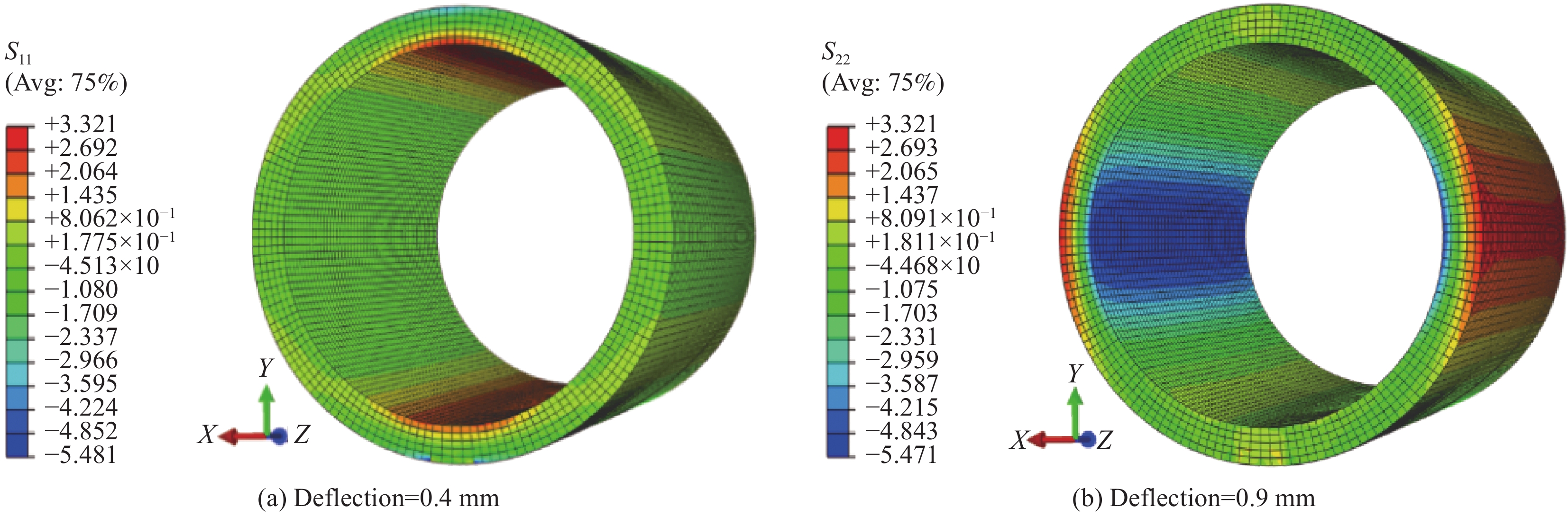
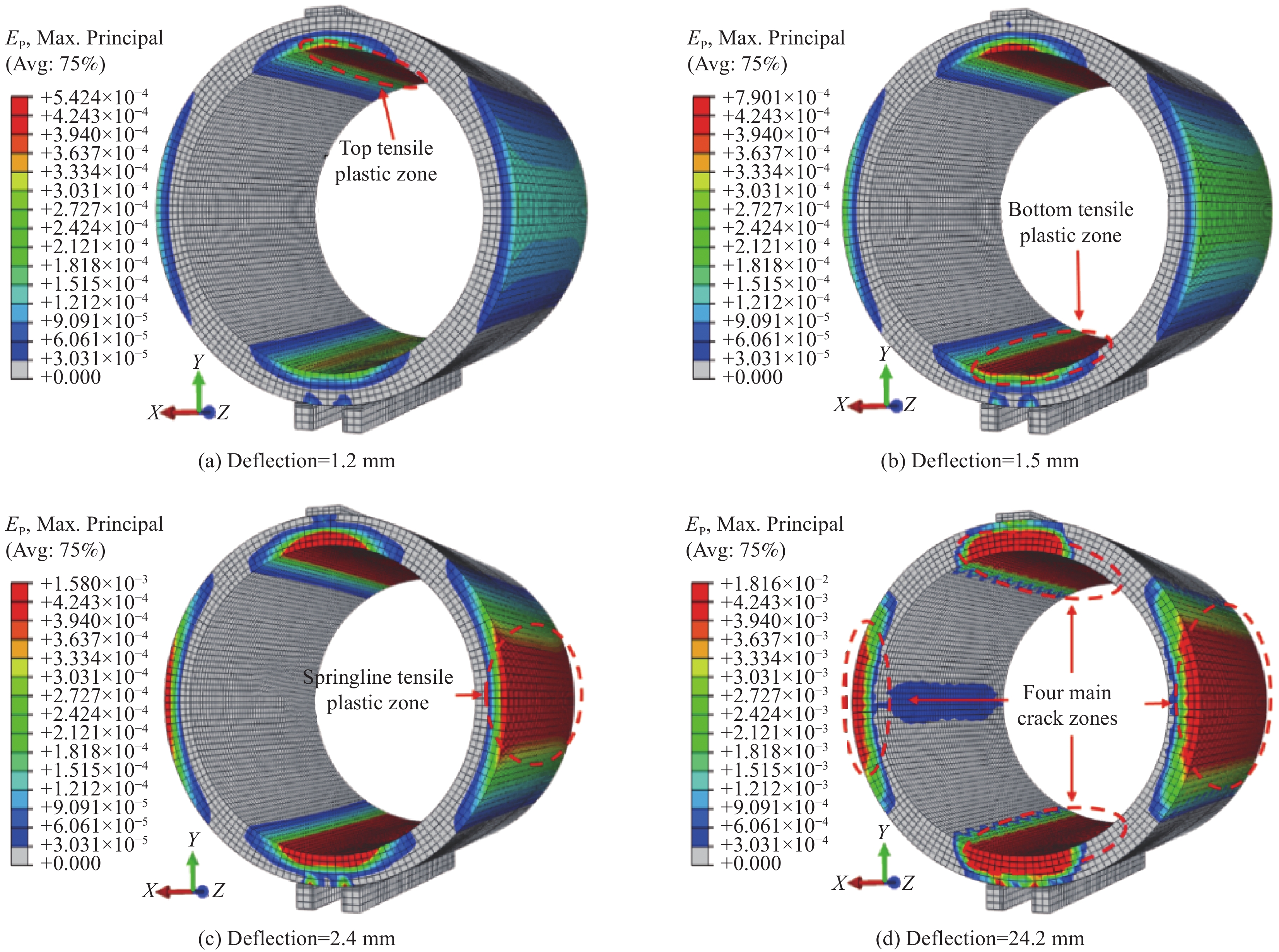
以FPF1-FPF2-CPF-S/C组试验管数值模拟结果为例,在管顶竖向位移加载至0.4 mm和0.9 mm左右时,管混凝土水平和竖向应力云图如图11所示,顶部和侧部混凝土分别达到最大拉应力即3.32 MPa,而后在顶部和侧部逐渐产生明显塑性区。对比钢筋/混凝土管节在试验与模拟中的破坏过程(图5),由图12的塑性区云图发展过程可知,随着竖向位移的增大,管顶部内壁混凝土的塑性应变高于其他区域混凝土的塑性应变(图12(a)),故首先出现受拉塑性开裂区[26];随后管底部内壁和侧部外壁混凝土进入塑性然后开裂(图12(b)和图12(c)),并向深部发展;最后混凝土压溃、环向钢筋达到极限拉应变,试验管达到最大承载力,此渐进弯曲破坏过程与试验现象基本一致。
![]() 图 11 钢筋/混凝土管(FPF1-FPF2-CPF-S/C组)水平和竖向应力云图Figure 11. Horizontal and vertical stress cloud map of reinforced concrete pipe (FPF1-FPF2-CPF-S/C group)
图 11 钢筋/混凝土管(FPF1-FPF2-CPF-S/C组)水平和竖向应力云图Figure 11. Horizontal and vertical stress cloud map of reinforced concrete pipe (FPF1-FPF2-CPF-S/C group)3.3.2 DL与管顶挠度曲线对比
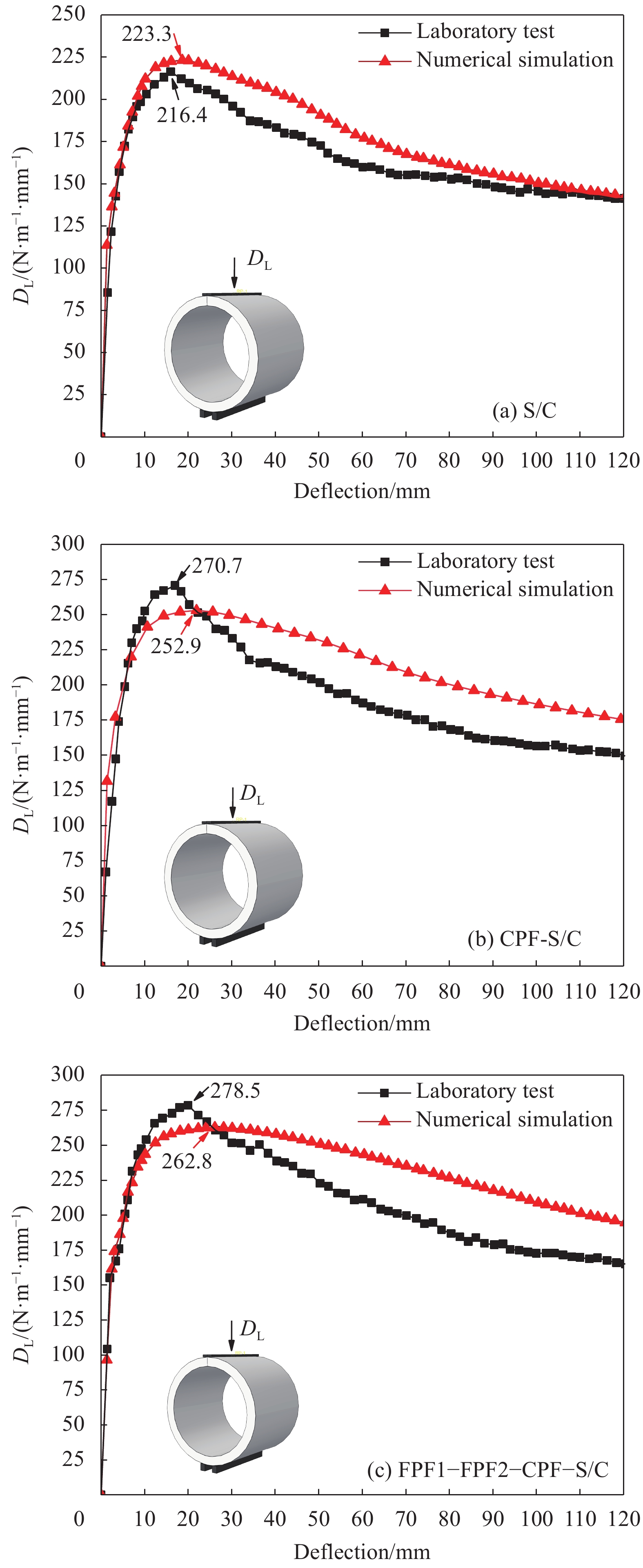
各组数值模拟和室内试验的DL与挠度曲线如图13所示,两者曲线形式较吻合。对于极限(峰值)强度值,模拟得到Du分别为220.8、252.9、262.8 N/m/mm,由于未考虑纤维的空间非均匀分布特点,相比室内试验极限强度值的误差最大为−6.6%。对于含有纤维试件的峰后阶段,由于模拟中未能考虑裂缝持续张开后,实际纤维被拔出和拉断从而失去桥接作用的影响,造成纤维在峰后同样发挥作用,使模拟结果高于试验结果,如图13(b)和图13(c)所示。此外,以峰后挠度40 mm对应的SPC-40值为例,对比结果如表9所示,FPF1-FPF2-CPF-S/C组比CPF-S/C、S/C组仍处于较高的水平,试验与模拟的最大误差为7.6%。总体而言,基于混凝土宏观拉压本构的有限元方法能够较好地体现出纤维对混凝土构件极限承载力和延性的贡献。
![]() 图 12 钢筋/混凝土管(FPF1-FPF2-CPF-S/C组)塑性区应变发展过程Figure 12. Development process of plastic zone strain of reinforced concrete pipe (FPF1-FPF2-CPF-S/C group)
图 12 钢筋/混凝土管(FPF1-FPF2-CPF-S/C组)塑性区应变发展过程Figure 12. Development process of plastic zone strain of reinforced concrete pipe (FPF1-FPF2-CPF-S/C group)![]() 图 13 钢筋/混凝土管数值模拟与室内试验的DL-挠度曲线对比Figure 13. Comparison of DL-deflection curves between numerical simulation and laboratory test for reinforced concrete pipes
图 13 钢筋/混凝土管数值模拟与室内试验的DL-挠度曲线对比Figure 13. Comparison of DL-deflection curves between numerical simulation and laboratory test for reinforced concrete pipes![]() 图 14 钢筋/混凝土管顶截面1-1弯矩与挠度关系曲线Figure 14. Relation curves of bending moment and deflection at the normal roof section 1-1 for reinforced concrete pipes表 9 钢筋/混凝土管SPC-40试验值与模拟值对比Table 9. Comparison of SPC-40 between numerical simulation and laboratory test for reinforced concrete pipes
图 14 钢筋/混凝土管顶截面1-1弯矩与挠度关系曲线Figure 14. Relation curves of bending moment and deflection at the normal roof section 1-1 for reinforced concrete pipes表 9 钢筋/混凝土管SPC-40试验值与模拟值对比Table 9. Comparison of SPC-40 between numerical simulation and laboratory test for reinforced concrete pipesPipe code Test value/
(N·m−2)Simulation
value/(N·m−2)Error/% S/C 31.2 33.6 7.7 CPF-S/C 37.3 38.7 3.8 FPF1-FPF2-CPF-S/C 40.4 40.9 1.4 进一步,得到截面1-1上混凝土弯矩与管顶挠度的关系曲线,如图14所示,可以看出,S/C、CPF-S/C和FPF1-FPF2-CPF-S/C三组的最大截面弯矩各为33.6、38.2、39.4 kN·m,FPF1-FPF2-CPF-S/C高于S/C组与CPF-S/C组约17.2%和3.2%。表明在加载后期FPF1-FPF2-CPF-S/C组仍能提供较高的截面弯矩,也反映出多尺度聚丙烯纤维混凝土管具有较高的裂后延性和残余强度。
![]() 图 15 掺聚丙烯粗纤维各组钢筋/混凝土管的Du与粗纤维掺量的拟合曲线Figure 15. Fitted curve between Du and crude fiber content of the reinforced concrete pipe with incorporating crude polypropylene fiber
图 15 掺聚丙烯粗纤维各组钢筋/混凝土管的Du与粗纤维掺量的拟合曲线Figure 15. Fitted curve between Du and crude fiber content of the reinforced concrete pipe with incorporating crude polypropylene fiber4. 纤维掺量对钢筋/混凝土管极限强度的影响
上述结果表明该有限元模型可以合理地预测纤维混凝土管的极限承载能力与荷载-挠度响应,可用于研究聚丙烯纤维掺量对钢筋/混凝土管节极限强度的影响规律,提高试验的可控性。因此,在前述三组模拟结果的基础上,针对单掺聚丙烯粗纤维-钢筋/混凝土管,设计10组不同掺量的模拟比较组进行计算;针对混掺多尺度聚丙烯纤维-钢筋/混凝土管,在总掺量一定下(6 kg/m3),设计8组粗细纤维占比不同的模拟比较组进行计算。
4.1 单掺聚丙烯粗纤维
单掺纤维组的Du值模拟结果如表10所示,随粗纤维掺量的变化趋势如图15所示,其中粗纤维含量设计的范围为0~9 kg/m3。结果表明,在该范围内钢筋/混凝土管节的极限强度并非随掺量单调变化,而是存在一个最优的单掺量值。由于混凝土的拉压性能直接影响了管极限强度的模拟结果,当聚丙烯粗纤维掺量过多时,会使混凝土各组分交界面缺陷增多,而且纤维的搭接缠绕削弱了基体的黏结强度,引起高掺量纤维混凝土对应拉压力学性能指标的降低,因此在推荐掺量下钢筋/混凝土管(CPF-S/C)的承载力模拟值较高。同时根据图15中的拟合公式,可得出在纤维含量约为6.22 kg/m3时,混凝土管的拟合极限强度最高为250.62 N/m/mm。
表 10 单掺聚丙烯粗纤维各组钢筋/混凝土管的Du模拟值Table 10. Du simulation value of each group of reinforced concrete with single-scale crude polypropylene fiberPipe code CPF content/
(kg·m−3)λk Ec/MPa fc/MPa εc/10−6 αc ft/MPa εt/10−6 αt Du/(N·m−1·mm−1) S/C 0 — 42 500 47.10 2 096.0 1.94 2.65 142.0 3.00 223.22 CPF-S/C-1 1.0 0.07 42 856 48.77 2 261.3 1.41 2.83 149.7 2.48 232.44 CPF-S/C-2 2.0 0.13 43 105 49.95 2 377.4 1.05 2.96 155.1 2.11 237.36 CPF-S/C-3 3.0 0.20 43 333 51.02 2 483.1 0.71 3.07 160.0 1.77 241.83 CPF-S/C-4 4.0 0.26 43 472 51.68 2 548.0 0.50 3.14 163.0 1.57 245.87 CPF-S/C-5 5.0 0.33 43 571 52.14 2 593.9 0.36 3.19 165.2 1.42 249.71 CPF-S/C 6.0 0.39 43 601 52.28 2 607.8 0.31 3.20 165.8 1.38 252.94 CPF-S/C-7 7.0 0.46 43 579 52.18 2 597.9 0.34 3.19 165.3 1.41 250.03 CPF-S/C-7.5 7.5 0.49 43 537 51.98 2 578.2 0.41 3.17 164.4 1.47 248.24 CPF-S/C-8 8.0 0.53 43 472 51.68 2 548.0 0.50 3.14 163.1 1.57 247.20 CPF-S/C-8.5 8.5 0.56 43 409 51.38 2 518.5 0.60 3.11 161.6 1.66 246.12 CPF-S/C-9.0 9.0 0.59 43 333 51.02 2 483.1 0.71 3.07 160.0 1.77 244.99 ![]() 图 16 混掺多尺度聚丙烯纤维各组钢筋/混凝土管的Du与聚丙烯粗纤维掺量拟合曲线Figure 16. Fitted curve between Du and crude fiber content of the reinforced concrete pipe with incorporating multi-scale polypropylene fibers
图 16 混掺多尺度聚丙烯纤维各组钢筋/混凝土管的Du与聚丙烯粗纤维掺量拟合曲线Figure 16. Fitted curve between Du and crude fiber content of the reinforced concrete pipe with incorporating multi-scale polypropylene fibers4.2 混掺多尺度聚丙烯纤维
混掺聚丙烯纤维组的Du值模拟结果如表11所示,随粗纤维掺量的变化趋势如图16所示。考虑总掺量(6 kg/m3)和细纤维推荐单掺量(0.9 kg/m3)的条件,取粗纤维含量的范围为4.2~6.0 kg/m3。与单掺相似,在该范围内钢筋/混凝土管节的极限强度也并非随粗纤维掺量增加而单调提升,模拟结果表明,FPF1=FPF2=0.4 kg/m3、CPF=5.2 kg/m3的FPF1-FPF2-CPF-S/C-5.2组表现出的极限强度略高于其他组。说明虽然通过不同粗细纤维配比,能够获得前述各拉压性能指标各自的最大值[23],但是混凝土管的极限强度受各个指标的影响程度不尽相同。相比之下,当混凝土抗拉峰值强度越高时,其模拟的管节Du值较大,即提升混凝土抗拉强度对混凝土管的承载能力更有利。同样,根据图16中的拟合公式,可得出在粗纤维含量约为5.18 kg/m3、两种细纤维含量分别为0.41 kg/m3时,混凝土管的拟合极限强度最高为263.78 N/m/mm。
表 11 混掺多尺度聚丙烯纤维各组钢筋/混凝土管的Du值Table 11. Du value of each group of reinforced concrete with multi-scale polypropylene fibersPipe code FPF1+FPF2+CPF content/(kg·m−3) λi+λj+λk Ec/MPa fc/MPa εc/10−6 αc ft/MPa εt/10−6 αt Du/(N·m−1·mm−1) CPF-S/C 0.0+0.0+6.0 0.00+0.00+0.39 43 600 52.28 2 607.8 0.31 3.20 165.8 1.38 252.94 FPF1-FPF2-CPF-S/C-5.8 0.1+0.1+5.8 0.08+0.02+0.38 44 519 49.60 2 692.2 0.22 3.30 176.3 1.50 255.54 FPF1-FPF2-CPF-S/C-5.6 0.2+0.2+5.6 0.16+0.04+0.37 44 816 48.23 2 770.7 0.16 3.37 186.6 1.58 258.44 FPF1-FPF2-CPF-S/C-5.4 0.3+0.3+5.4 0.24+0.06+0.36 44 543 48.16 2 843.4 0.12 3.40 196.6 1.61 262.78 FPF1-FPF2-CPF-S/C-5.2 0.4+0.4+5.2 0.32+0.08+0.34 43 821 49.96 2 912.0 0.12 3.40 206.0 1.59 265.45 FPF1-FPF2-CPF-S/C-5 0.5+0.5+5.0 0.40+0.10+0.33 42 631 52.65 2 973.6 0.14 3.37 215.4 1.54 263.47 FPF1-FPF2-CPF-S/C 0.6+0.6+4.8 0.48+0.13+0.32 40 792 56.43 3 018.4 0.12 3.32 224.5 1.40 262.75 FPF1-FPF2-CPF-S/C-4.6 0.7+0.7+4.6 0.56+0.15+0.30 39 076 63.10 3 072.8 0.21 3.23 232.8 1.27 259.01 FPF1-FPF2-CPF-S/C-4.4 0.8+0.8+4.4 0.64+0.17+0.29 36 880 70.14 3 118.3 0.29 3.11 241.4 1.11 253.01 FPF1-FPF2-CPF-S/C-4.2 0.9+0.9+4.2 0.72+0.19+0.28 34 478 78.50 3 157.8 0.40 2.97 249.8 0.94 251.45 5. 结 论
(1) 聚丙烯粗纤维能够改善三点试验下钢筋/混凝土管节的破坏形态,纤维通过桥接作用调节局部应力,使管节顶部裂缝分散增多,控制了内壁的宏观裂缝扩展,有效防止管节混凝土产生碎裂、剥落等严重破坏。
(2) 针对环向配筋率为1%的1 m内径管节,纤维掺量为6 kg/m3时,单掺聚丙烯粗纤维混凝土管和混掺三种尺度聚丙烯纤维混凝土管的使用强度和极限强度分别比传统混凝土管提高了31.1%、36.4%和25.1%、28.7%,加入纤维使钢筋/混凝土管满足了Ⅴ级管的使用要求,在顶管施工中能够提供更高的抗裂能力。
(3) 与内径1 m的标准管节相比,含有聚丙烯纤维的混凝土管节拥有更高的开裂后延性,而且多尺度纤维混凝土管节的开裂后强度SPC值较单掺纤维混凝土管提升范围为4.6%~10.0%,粗细纤维的协同作用有利于发挥出更好的吸能增韧效果。
(4) 有限元方法能够计算纤维混凝土管节三点外压试验的极限承载能力与荷载挠度响应,反映管节的宏观破坏过程。针对1 m内径管节的极限强度值,单掺一种和混掺三种尺度的聚丙烯纤维均存在粗纤维的最优掺量,分别为6.22 kg/m3和5.18 kg/m3。
-
![]()
图 2 钢筋/混凝土管节试件截面与配筋
Figure 2. Section and reinforcement of reinforced concrete pipe specimen
![]()
图 3 三点试验加载装置示意图
Figure 3. Schematic diagram of the pipe three-edge-bearing test loading device
![]()
图 4 钢筋/混凝土管节三点试验加载与记录的过程
Figure 4. Test process of loading and recording of reinforced concrete pipe three-edge-bearing test
![]()
图 5 三类钢筋/混凝土试验管的开裂破坏形态
Figure 5. Cracking and failure modes of three types of test reinforced concrete pipes
![]()
图 6 钢筋/混凝土管DL与管顶挠度的关系曲线
Figure 6. Relation curve between DL and top deflection of reinforced concrete pipes
![]()
图 7 计算开裂后强度SPC值的钢筋/混凝土管荷载-挠度曲线
Figure 7. Load-deflection curves of reinforced concrete pipes to calculate post-cracking strength SPC value
δ—Deflection; δpeak—Peak deflection corresponding to peak load; Epost—Area bounded by a deflection to peak deflection and a deflection
![]()
图 8 不同挠度下三组钢筋/混凝土管的峰后开裂强度SPC
Figure 8. Post-cracking strength SPC at different deflection values for three reinforced concrete pipes
![]()
图 9 钢筋/混凝土管节三点试验的有限元数值模型
Figure 9. Finite element numerical model for the three-edge-bearing test of reinforced concrete pipe
uX, uY, uZ—Displacement values in each direction of X, Y, and Z in the space rectangular coordinate system
![]()
图 10 聚丙烯纤维/混凝土单轴拉压应力-应变曲线
Figure 10. Uniaxial compressive and tensile stress-strain curves of polypropylene fiber/concrete
fc, ft—Compressive and tensile strength vaules of concrete; Ec—Elasticity modulus of concrete; αc, αt—Shape parameters of the falling section of the concrete compressive and tensile stress-strain curves; σc and σt—Compressive and tensile stress vaules of concrete; ε—Strain vaule of concrete; ρc, ρt, n and x—Intermediate parameters during the stress calculation process; εc and εt—Compressive and tensile peak strain vaules of concrete
![]()
图 11 钢筋/混凝土管(FPF1-FPF2-CPF-S/C组)水平和竖向应力云图
Figure 11. Horizontal and vertical stress cloud map of reinforced concrete pipe (FPF1-FPF2-CPF-S/C group)
![]()
图 12 钢筋/混凝土管(FPF1-FPF2-CPF-S/C组)塑性区应变发展过程
Figure 12. Development process of plastic zone strain of reinforced concrete pipe (FPF1-FPF2-CPF-S/C group)
![]()
图 13 钢筋/混凝土管数值模拟与室内试验的DL-挠度曲线对比
Figure 13. Comparison of DL-deflection curves between numerical simulation and laboratory test for reinforced concrete pipes
![]()
图 14 钢筋/混凝土管顶截面1-1弯矩与挠度关系曲线
Figure 14. Relation curves of bending moment and deflection at the normal roof section 1-1 for reinforced concrete pipes
![]()
图 15 掺聚丙烯粗纤维各组钢筋/混凝土管的Du与粗纤维掺量的拟合曲线
Figure 15. Fitted curve between Du and crude fiber content of the reinforced concrete pipe with incorporating crude polypropylene fiber
![]()
图 16 混掺多尺度聚丙烯纤维各组钢筋/混凝土管的Du与聚丙烯粗纤维掺量拟合曲线
Figure 16. Fitted curve between Du and crude fiber content of the reinforced concrete pipe with incorporating multi-scale polypropylene fibers
表 1 不同尺度聚丙烯纤维的物理力学性能
Table 1 Physical and mechanical properties of polypropylene fibers of different scales
Fiber code Diameter/mm Length/mm Aspect ratio Tensile
strength/MPaElasticity
modulus/GPaDensity/
(kg·m−3)Recommended single
dosage/(kg·m−3)FPF1 0.026 19 730.8 641 8.5 0.91 0.9 FPF2 0.1 19 190 322 3.9 0.91 0.9 CPF 0.8 50 62.5 706 7.4 0.95 6.0 Notes: FPF1—Type of fine polypropylene fiber; FPF2—Another type of fine polypropylene fiber; CPF—Crude polypropylene fiber.  下载: 导出CSV
表 2 C50混凝土设计配合比
Table 2 Design mix ratio of C50 concrete
Material Cement Coarse aggregate Sand Water Water reducer 10-20 mm 5-10 mm Dosage/(kg·m−3) 375 545 545 850 135 3.75
下载: 导出CSV
表 3 试验各组不同尺度聚丙烯纤维的配比
Table 3 Proportions of polypropylene fibers of different scales in each specimen
kg·m−3 Pipe code Fine polypropylene fibers Crude polypropylene fiber Total content FPF1 FPF2 CPF S/C 0 0 0 0 CPF-S/C 0 0 6 6 FPF1-FPF2-CPF-S/C 0.6 0.6 4.8 6 Notes: S/C—Reinforced concrete pipe without fiber; CPF-S/C—Reinforced concrete pipe with crude polypropylene fiber; FPF1-FPF2-CPF-S/C—Reinforced concrete pipe with multi-scale polypropylene fibers.
下载: 导出CSV
表 4 基于ASTM C76[17]的钢筋/混凝土管节等级强度要求
Table 4 Grade strength requirements for reinforced concrete pipe based on ASTM C76[17]
Concrete pipe class D-load(DL)/(N·m−1·mm−1) D-load0.3(D0.3) D-loadu(Du) I 40 60 II 50 75 III 65 100 IV 100 150 V 140 175 Notes: D-load(DL)—Supporting load value of pipe; D-load0.3(D0.3)—Load value when crack width is 0.3 mm, namely service strength; D-loadu(Du)—Maximum load value, namely ultimate strength.
下载: 导出CSV
表 5 各钢筋/混凝土试验管节的使用强度与极限强度
Table 5 Service load and ultimate load of each reinforced concrete pipes
Pipe code DL/(N·m−1·mm−1) D0.3 Du S/C 126.7 216.4 CPF-S/C 164.8 270.7 FPF1-FPF2-CPF-S/C 171.4 278.5
下载: 导出CSV
表 6 钢筋/混凝土管节有限元模型单元类型与数量
Table 6 Number and types of the model elements of reinforced concrete pipe
Model part Element number Element type Concrete pipe 37 500 C3D8I Lower bearing strips 1 900 Upper bearing strip 600 Steel cage 5 390 T3D2
下载: 导出CSV
表 7 钢筋/混凝土管拉压力学性能指标
Table 7 Tensile and compressive mechanical properties indexes of reinforced concrete pipes
Pipe code λi+λj+λk Ec/MPa fc/MPa εc/10−6 αc ft/MPa εt/10−6 αt S/C 0+0+0 42 500 47.1 2 096 1.94 2.65 142 3 CPF-S/C 0+0+0.39 43 601 52.3 2 607.8 0.31 3.20 165.8 1.38 FPF1-FPF2-CPF-S/C 0.48+0.13+0.32 40 792 56.4 3 018.4 0.12 3.32 224.5 1.40 Note: λi , λj and λk—Eigenvalues of FPF1, FPF2 and CPF.
下载: 导出CSV
表 8 混凝土损伤塑性模型(CDP)模型的塑性参数取值
Table 8 Values of the concrete damaged plastic model (CDP) model plasticity parameters
CDP model plasticity parameter Value Dilatation angel Ψ/(°) 36 Flow potential eccentricity 0.1 fb0/fc0 1.16 Stress invariant ratio K 0.67 Viscosity parameter μ 0.0009-0.001 Note: fb0/fc0—Ratio of ultimate strength of biaxial compression to uniaxial compression.
下载: 导出CSV
表 9 钢筋/混凝土管SPC-40试验值与模拟值对比
Table 9 Comparison of SPC-40 between numerical simulation and laboratory test for reinforced concrete pipes
Pipe code Test value/
(N·m−2)Simulation
value/(N·m−2)Error/% S/C 31.2 33.6 7.7 CPF-S/C 37.3 38.7 3.8 FPF1-FPF2-CPF-S/C 40.4 40.9 1.4
下载: 导出CSV
表 10 单掺聚丙烯粗纤维各组钢筋/混凝土管的Du模拟值
Table 10 Du simulation value of each group of reinforced concrete with single-scale crude polypropylene fiber
Pipe code CPF content/
(kg·m−3)λk Ec/MPa fc/MPa εc/10−6 αc ft/MPa εt/10−6 αt Du/(N·m−1·mm−1) S/C 0 — 42 500 47.10 2 096.0 1.94 2.65 142.0 3.00 223.22 CPF-S/C-1 1.0 0.07 42 856 48.77 2 261.3 1.41 2.83 149.7 2.48 232.44 CPF-S/C-2 2.0 0.13 43 105 49.95 2 377.4 1.05 2.96 155.1 2.11 237.36 CPF-S/C-3 3.0 0.20 43 333 51.02 2 483.1 0.71 3.07 160.0 1.77 241.83 CPF-S/C-4 4.0 0.26 43 472 51.68 2 548.0 0.50 3.14 163.0 1.57 245.87 CPF-S/C-5 5.0 0.33 43 571 52.14 2 593.9 0.36 3.19 165.2 1.42 249.71 CPF-S/C 6.0 0.39 43 601 52.28 2 607.8 0.31 3.20 165.8 1.38 252.94 CPF-S/C-7 7.0 0.46 43 579 52.18 2 597.9 0.34 3.19 165.3 1.41 250.03 CPF-S/C-7.5 7.5 0.49 43 537 51.98 2 578.2 0.41 3.17 164.4 1.47 248.24 CPF-S/C-8 8.0 0.53 43 472 51.68 2 548.0 0.50 3.14 163.1 1.57 247.20 CPF-S/C-8.5 8.5 0.56 43 409 51.38 2 518.5 0.60 3.11 161.6 1.66 246.12 CPF-S/C-9.0 9.0 0.59 43 333 51.02 2 483.1 0.71 3.07 160.0 1.77 244.99
下载: 导出CSV
表 11 混掺多尺度聚丙烯纤维各组钢筋/混凝土管的Du值
Table 11 Du value of each group of reinforced concrete with multi-scale polypropylene fibers
Pipe code FPF1+FPF2+CPF content/(kg·m−3) λi+λj+λk Ec/MPa fc/MPa εc/10−6 αc ft/MPa εt/10−6 αt Du/(N·m−1·mm−1) CPF-S/C 0.0+0.0+6.0 0.00+0.00+0.39 43 600 52.28 2 607.8 0.31 3.20 165.8 1.38 252.94 FPF1-FPF2-CPF-S/C-5.8 0.1+0.1+5.8 0.08+0.02+0.38 44 519 49.60 2 692.2 0.22 3.30 176.3 1.50 255.54 FPF1-FPF2-CPF-S/C-5.6 0.2+0.2+5.6 0.16+0.04+0.37 44 816 48.23 2 770.7 0.16 3.37 186.6 1.58 258.44 FPF1-FPF2-CPF-S/C-5.4 0.3+0.3+5.4 0.24+0.06+0.36 44 543 48.16 2 843.4 0.12 3.40 196.6 1.61 262.78 FPF1-FPF2-CPF-S/C-5.2 0.4+0.4+5.2 0.32+0.08+0.34 43 821 49.96 2 912.0 0.12 3.40 206.0 1.59 265.45 FPF1-FPF2-CPF-S/C-5 0.5+0.5+5.0 0.40+0.10+0.33 42 631 52.65 2 973.6 0.14 3.37 215.4 1.54 263.47 FPF1-FPF2-CPF-S/C 0.6+0.6+4.8 0.48+0.13+0.32 40 792 56.43 3 018.4 0.12 3.32 224.5 1.40 262.75 FPF1-FPF2-CPF-S/C-4.6 0.7+0.7+4.6 0.56+0.15+0.30 39 076 63.10 3 072.8 0.21 3.23 232.8 1.27 259.01 FPF1-FPF2-CPF-S/C-4.4 0.8+0.8+4.4 0.64+0.17+0.29 36 880 70.14 3 118.3 0.29 3.11 241.4 1.11 253.01 FPF1-FPF2-CPF-S/C-4.2 0.9+0.9+4.2 0.72+0.19+0.28 34 478 78.50 3 157.8 0.40 2.97 249.8 0.94 251.45
下载: 导出CSV
-
[1] 赖德贤. 顶管工程中顶管的计算与管材选用[D]. 广州: 华南理工大学, 2010. LAI Dexian. Calculation and selection of pipe on pipe jacking works[D]. Guangzhou: South China University of Technology, 2010(in Chinese).
[2] AL RIKABI F T, SARGAND S M, KURDZIEL J. Evaluation of synthetic fiber reinforced concrete pipe performance using three-edge bearing test[J]. Journal of Testing and Evaluation,2019,47 (2):942-958.
[3] MOHAMED N, SOLIMAN A M, NEHDI M L. Full-scale pipes using dry-cast steel fibre-reinforced concrete[J]. Construction and Building Materials,2014,72:411-422. DOI: 10.1016/j.conbuildmat.2014.09.025
[4] ABOLMAALI A, MIKHAYLOVA A, WILSON A, et al. Performance of steel fiber-reinforced concrete pipes[J]. Transportation Research Record,2012(2313):168-177.
[5] LEE S, PARK Y, ABOLMAALI A. Investigation of flexural toughness for steel-and-synthetic-fiber-reinforced concrete pipes[J]. Structures,2019,19:203-211. DOI: 10.1016/j.istruc.2018.12.010
[6] BURATTI N, MAZZOTTI C, SAVOIA M. Post-cracking behaviour of steel and macro-synthetic fibre-reinforced concretes[J]. Construction and Building Materials,2011,25 (5):2713-2722. DOI: 10.1016/j.conbuildmat.2010.12.022
[7] WILSON A, ABOLMAALI A. Performance of synthetic fiber-reinforced concrete pipes[J]. Journal of Pipeline Systems Engineering and Practice,2014,5(3):1-7.
[8] AL RIKABI F T, SARGAND S M, KURDZIEL J, et al. Experimental investigation of thin-wall synthetic fiber-reinforced concrete pipes[J]. ACI Structural Journal,2018,115(6):1671-1681.
[9] PARK Y, ABOLMAALI A, MOHAMMADAGHA M, et al. Structural performance of dry-cast rubberized concrete pipes with steel and synthetic fibers[J]. Construction and Building Materials,2015,77:218-226. DOI: 10.1016/j.conbuildmat.2014.12.061
[10] 赵凯月, 王艳, 张金团, 等. 混杂纤维混凝土研究现状[J]. 混凝土, 2018(3):132-137, 140. DOI: 10.3969/j.issn.1002-3550.2018.03.033 ZHAO Kaiyue, WANG Yan, ZHANG Jintuan, et al. Research status of hybrid fiber reinforced concrete[J]. Concrete,2018(3):132-137, 140(in Chinese). DOI: 10.3969/j.issn.1002-3550.2018.03.033
[11] 丁一宁, 王卿, 林宇栋. 纤维对开裂后混凝土渗透性及裂缝恢复的影响[J]. 复合材料学报, 2017, 34(8):1853-1861. DING Yining, WANG Qing, LIN Yudong. Effect of fibers on permeability and crack relaxation of cracked concrete[J]. Acta Materiae Compositae Sinica,2017,34(8):1853-1861(in Chinese).
[12] 罗洪林, 杨鼎宜, 周兴宇, 等. 不同长径比聚丙烯纤维增强混凝土的力学特性[J]. 复合材料学报, 2019, 36(8):1935-1948. LUO Honglin, YANG Dingyi, ZHOU Xingyu, et al. Mechanical properties of polypropylene fiber reinforced concrete with different aspect ratios[J]. Acta Materiae Compositae Sinica,2019,36(8):1935-1948(in Chinese).
[13] 梁宁慧, 刘新荣, 孙霁. 多尺度聚丙烯纤维混凝土抗裂性能的试验研究[J]. 煤炭学报, 2012, 37(8):1304-1309. LIANG Ninghui, LIU Xinrong, SUN Ji. Experimental study of crack resistance for multi-scale polypropylene fiber reinforced concrete[J]. Journal of China Coal Society,2012,37(8):1304-1309(in Chinese).
[14] 梁宁慧, 胡杨, 钟杨, 等. 多尺度聚丙烯纤维混凝土孔结构及抗冻性[J]. 重庆大学学报, 2019, 42(11):38-46. DOI: 10.11835/j.issn.1000-582X.2019.11.005 LIANG Ninghui, HU Yang, ZHONG Yang, et al. Study on pore structure and frost resistance of multi-scale polypropylene fiber reinforced concrete[J]. Journal of Chongqing University,2019,42(11):38-46(in Chinese). DOI: 10.11835/j.issn.1000-582X.2019.11.005
[15] 梁宁慧. 多尺度聚丙烯纤维混凝土力学性能试验和拉压损伤本构模型研究[D]. 重庆: 重庆大学, 2014. LIANG Ninghui. The mechanics performance test of multi-scale polypropylene fiber concrete and the study of tension and compression damage constitutive model[D]. Chongqing: Chongqing University, 2014(in Chinese).
[16] 中国国家标准化管理委员会. 混凝土和钢筋混凝土排水管试验方法: GB/T 16752—2017[S]. 北京: 中国标准出版社, 2018. Standardization Administration of the People’s Republic of China. Test methods of concrete reinforced concrete drainage and sewer pipes: GB/T 16752—2017[S]. Beijing: China Standards Press, 2018(in Chinese).
[17] American Society for Testing and Materials. Standard test method for concrete pipe, concrete box sections, manhole sections, or tile(metric): ASTM C497—19[S]. West Conshohocken: ASTM, 2019.
[18] American Society for Testing and Materials. Standard specification for reinforced concrete culvert, storm drain, and sewer pipe: ASTM C76—19a[S]. West Conshohocken: ASTM, 2019.
[19] FUENTE A D L, FIGUEIREDO A D D, AGUADO A, et al. Steel fibre reinforced concrete pipes. Part 2: Numerical model to simulate the crushing test[J]. Revista IBRACON de Estruturas e Materiais,2012,5(1):12-25. DOI: 10.1590/S1983-41952012000100003
[20] 梁宁慧, 钟杨, 刘新荣. 多尺寸聚丙烯纤维混凝土抗弯韧性试验研究[J]. 中南大学学报(自然科学版), 2017, 48(10):2783-2789. DOI: 10.11817/j.issn.1672-7207.2017.10.032 LIANG Ninghui, ZHONG Yang, LIU Xinrong. Experimental study of flexural toughness for multi-scale polypropylene fiber reinforced concrete[J]. Journal of Central South University (Science and Technology),2017,48(10):2783-2789(in Chinese). DOI: 10.11817/j.issn.1672-7207.2017.10.032
[21] MOHAMED N, NEHDI M L. Rational finite element assisted design of precast steel fibre reinforced concrete pipes[J]. Engineering Structures,2016,124:196-206. DOI: 10.1016/j.engstruct.2016.06.014
[22] 中华人民共和国住房和城乡建设部. 混凝土结构设计规范: GB 50010—2010[S]. 北京; 中国建筑工业出版社. 2011. Ministry of Housing and Urban-Rural Development of the People's Republic of China. Code for design of concrete structures: GB 50010—2010[S]. Beijing: China Architecture & Building Press, 2011(in Chinese).
[23] 缪庆旭. 多尺度聚丙烯纤维干硬性混凝土拉压性能试验研究[D]. 重庆: 重庆大学, 2019. MIAO Qingxu, Experimental study on tensile and compression properties of multi-scale polypropylene fiber roller compacted concrete[D]. Chongqing: Chongqing University, 2019(in Chinese).
[24] RAZA A, ALI B, REHMAN A U. Structural performance of steel-tube concrete columns confined with CFRPs: Numerical and theoretical study[J]. Iranian Journal of Science and Technology-Transactions of Civil Engineering,2020,45(6):1575-1592.
[25] AL RIKABI F T, SARGAND S M, HUSSEIN H H. Design proposal for synthetic fiber-reinforced concrete pipes using finite element analysis[J]. Journal of Testing and Evaluation,2020,48(2):871-895.
[26] 过镇海. 钢筋混凝土原理[M]. 北京: 清华大学出版社, 2013: 26. GUO Zhenhai. Principle of reinforced concrete[M]. Beijing: Tsinghua University Press, 2013: 26(in Chinese).
-
期刊类型引用(6)
1. 唐百晓. 聚丙烯纤维混凝土纤维增强作用机理研究. 粘接. 2023(02): 78-82 .  百度学术
百度学术
2. 李锐,王飞,张凯宏. 聚丙烯纤维轻质高强混凝土动态力学特性研究. 实验技术与管理. 2023(02): 115-120+139 . 百度学术
3. 贾静恩,张彬. 扰动荷载下聚丙烯纤维喷射混凝土力学性能研究. 复合材料科学与工程. 2023(06): 73-79+94 . 百度学术
4. 郑祥盘,何伟,魏作友,陈龙. 树脂混凝土微型顶管技术研究与分析. 化学工程与装备. 2023(06): 10-15+22 . 百度学术
5. 肖敏,欧阳春生,杨芬,夏艳波,王威. 聚丙烯纤维混凝土受弯构件正截面承载力的理论分析. 新型工业化. 2022(06): 170-173+255 . 百度学术
6. 梁宁慧,游秀菲,兰菲,刘新荣,邓志云. 玄武岩粗聚丙烯纤维钢筋混凝土管力学性能. 地下空间与工程学报. 2022(04): 1177-1187+1198 . 百度学术
其他类型引用(0)
-


计量
- 文章访问数: 1421
- HTML全文浏览量: 533
- PDF下载量: 67
- 被引次数: 6
