

Bond behavior of deformed steel bars lap-splice in ultra high performance concrete
-
摘要: 超高性能混凝土(UHPC)是一种高强度、高韧性和高耐久性的水泥基复合材料。为了研究钢筋/UHPC的搭接黏结性能,进行了21组考虑搭接长度、纤维掺量和配箍率影响的钢筋搭接对拉拔出试验,3组考虑锚固长度影响的钢筋直接拔出锚固试验;试验出现了劈裂拔出破坏和钢筋拉断破坏2种破坏模式;钢筋/UHPC平均黏结强度随钢筋埋置长度的增大而减小,随配箍率的增大而增大;钢纤维掺量的增大,有利于增大对UHPC的约束作用,增加配箍率和适当增大纤维掺量均能减小钢筋/UHPC的临界搭接长度;结合前人的试验结果,拟合得到平均锚固和搭接黏结强度计算公式及临界锚固和搭接长度计算公式,根据混凝土结构设计规范,建立了钢筋/UHPC锚固和搭接长度简化算法,计算结果较为准确。Abstract: Ultra high performance concrete (UHPC) is a kind of cement-based material with high strength, high toughness and high durability. To study the lap-spliced bond performance of steel bars in UHPC, 21 groups of lap-spliced specimens were tested considering the parameters of lap length, fibers content and stirrups ratio. 3 groups of pull-out specimens considering a parameter of anchorage length were conducted to be control groups. Two failure modes, those are splitting-pull-out failure and steel-bar-rupture failure appear. The average bond strength decreases with the increase of embedded length and increases with the increase of stirrup ratio. The steel fibers enhance the confinement for UHPC. Increasing the stirrup ratio and fiber content can reduce the lap-spliced length of the steel bars in UHPC. Combining with the previous research, average bond strength and development length as well as splice length formulas were fitted. Simplified algorithms of development length and splice length were proposed according to the Code for Design of Concrete Stuctures, and the results agree well with the test results.
-
超高性能混凝土(UHPC)是一种具有高强度、高韧性、高耐久性的水泥基复合材料,与钢筋具有超高的黏结强度[1-2]。UHPC在重载、大跨、抗震、抗爆和抗冲击等结构中具有广阔的应用前景。与钢筋/普通混凝土结构相同,配筋/UHPC结构中存在钢筋连接接长问题,最简便的钢筋连接接长方式是搭接连接,钢筋/UHPC的高黏结强度可以使钢筋的搭接长度大幅缩短,使UHPC得以用于预制装配式桥梁结构[3-4]和建筑结构[5]中预制构件的连接,仅需较小的搭接长度且钢筋无需弯钩锚固,减少了施工的复杂程度和现场湿作业量。另外,Dagenais等[6]还应用UHPC的高黏结性能加固搭接长度不足的钢筋/混凝土结构,取得了良好效果。
采用直接拔出锚固试验是较为常用的研究钢筋/UHPC黏结性能的试验方法。Graybeal[7]将直径为12.7 mm、15.9 mm、19.1 mm的钢筋分别锚固75 mm、100 mm、125 mm于UHPC圆柱体中,均发生钢筋拉断破坏而未出现黏结破坏。Swenty等[8]采用直径为12.7 mm的钢筋锚固于边长为150 mm的立方体试块中,采用两种不同配合比的UHPC,分别实现了钢筋的屈服和拉断。Holschemacher等[9]采用直径为12 mm的钢筋锚固在UHPC圆柱体中,测得黏结强度高达60 MPa。Jungwirth等[10]对直径为20 mm和12 mm的钢筋进行锚固试验,黏结强度分别达到38 MPa和66 MPa。Alkaysi等[11]通过锚固试验研究了UHPC的早期龄期(1天、3天、7天)的黏结强度,结果表明在7天龄期时,可以达到75%的最终黏结强度。Graybeal[12]的试验结果表明:影响UHPC黏结强度的主要因素有保护层厚度、锚固长度和钢筋直径。Bae等[13]通过锚固试验研究发现:钢纤维体积分数由0增加到1%,钢筋与UHPC的黏结强度提高了1倍,由1%增加到2%,黏结强度提高幅度变小。Saleem等[14]研究了高强钢筋在UHPC中锚固长度,结果表明:直径9.5 mm和22.2 mm高强钢筋的锚固长度分别为12倍和18倍的钢筋直径。安明喆等[15]通过钢筋拔出试验,研究了变形钢筋直径和锚固长度对钢筋/活性粉末混凝土(RPC)黏结性能的影响,提出变形钢筋与RPC的极限黏结强度与锚固长度的计算公式。邓宗才等[16]通过54个中心拉拔、6个立方体偏心拉拔、6个棱柱体中心拉拔和6个板式中心拉拔锚固试件系统研究了钢筋埋长、保护层厚度、钢筋直径、RPC强度和钢纤维体积掺量等因素对钢筋/RPC黏结性能的影响规律。贾方方[17]通过5组直接拔出锚固试件研究了不同纤维体积掺量对钢筋/RPC黏结性能的影响,结果表明:纤维体积掺量从0增大到2%,黏结强度逐渐增大。
采用直接拔出锚固试件对钢筋/UHPC黏结性能的研究较为充分,但加载时锚固试件钢筋受拉,周围UHPC受压,与实际结构构件受力不符,锚固试件加载端容易受到约束,限制UHPC的开裂,测得的黏结强度偏高,且目前尚未建立直接拔出锚固黏结与实际搭接黏结的关系,对实际应用指导有限。采用梁式搭接试件研究的钢筋/UHPC黏结性能与实际构件搭接受力最为相符。Dagenais等[6, 18]将UHPC应用于钢筋搭接长度不足的钢筋/混凝土受弯构件的加固中,分别进行了单调和滞回试验研究,研究结果表明钢筋/UHPC的搭接黏结强度约为普通混凝土的两倍,采用UHPC加固过的构件可以适用于地震区。Al-Quraishi等[19]试验了6根梁式钢筋搭接试件,研究了钢筋在UHPC中搭接性能,结果表明UHPC的劈裂是钢筋搭接失效的主要破坏模式。由于梁式搭接试件制作和加载过程较为复杂,研究数量有限。
钢筋搭接对拉拔出试验能较好地反应实际构件的搭接受力,且能简化试验。徐有邻等[20]通过普通混凝土中钢筋搭接对拉拔出试验和梁中搭接钢筋传力对比试验,观察了搭接钢筋的传力机制、受力特征和破坏形态,发现对拉试验与梁中钢筋搭接试验结果基本相符。Graybeal[21]将强度为1 860 MPa的钢绞线在掺加不同纤维的UHPC中搭接,进行了对拉拔出试验,钢筋在掺加钢纤维的UHPC (抗压强度为162 MPa)中所需的搭接长度小于掺加PVA纤维的UHPC (抗压强度为134 MPa)。Lagier等[22]通过钢筋搭接对拉拔出试验研究了纤维体积掺量和搭接长度对搭接性能的影响,通过钢筋内部开槽粘贴应变片研究了钢筋沿搭接长度的应变分布。方志等[23]试验了39个钢筋/RPC搭接对拉拔出试件,发生破坏时,搭接区域的搭接黏结强度随搭接长度增大而略有减小,随RPC强度和配箍率的增大而增大,并研究了钢筋净距对搭接黏结强度的影响,在1倍钢筋直径时黏结强度达到最大。
目前,针对钢筋/UHPC锚固试验的研究较充分,钢筋搭接试验的研究有限,且未建立钢筋/UHPC锚固和搭接之间的关系及指导实际设计的算法。本文进行了21组考虑搭接长度、纤维体积掺量和配箍率影响的钢筋/UHPC搭接对拉拔出试验,3组考虑锚固长度影响的钢筋/UHPC直接拔出锚固试验。研究钢筋锚固和搭接连接试件的破坏形态,分析钢筋搭接黏结强度的影响因素,参考相关文献,拟合得到钢筋/UHPC锚固和搭接试件的平均黏结强度计算公式及锚固和搭接长度计算公式,建立钢筋/UHPC锚固和搭接长度简化算法。
1. 试验概况
1.1 试件设计
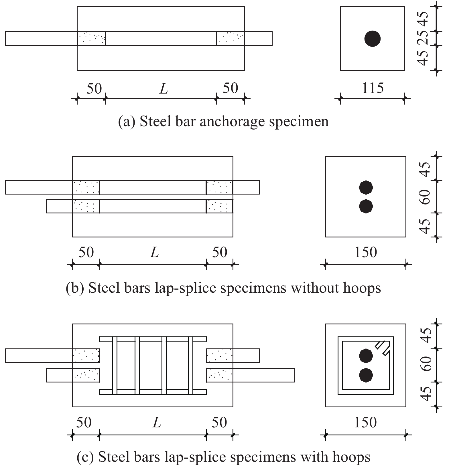
设计了21组钢筋/UHPC搭接连接试件,每组3个试件完全相同,试件的主要变化参数有搭接长度、纤维体积掺量和配箍率。采用的钢筋直径为25 mm,搭接长度范围在3d~12d (d为钢筋直径)不等,以期发生多种破坏形态。纤维体积分数取值为2%、3%和4%。箍筋作为一种加强措施,其体积配箍率为0.67%、1.35%和2.25%。试件的截面尺寸为150 mm×150 mm,钢筋净距为10 mm;另外,设计了3组钢筋锚固试件作为对比试件,试件的截面尺寸为115 mm×115 mm,以保证与钢筋搭接连接试件的保护层厚度一致,均为45 mm;为了减轻试件端部对黏结段的影响,采用塑料套管将端部钢筋与UHPC隔离,长度为50 mm,因此,试件的长度为L+2×50 mm (L为搭接长度),试件尺寸如图1所示。试件参数及主要试验结果如表1所示。
![]() 图 1 钢筋/超高性能混凝土(UHPC)搭接试件尺寸及制作(单位:mm)Figure 1. Size and fabrication of steel bars/ultra high performance concrete (UHPC) lap-splice specimens (Unit: mm)
图 1 钢筋/超高性能混凝土(UHPC)搭接试件尺寸及制作(单位:mm)Figure 1. Size and fabrication of steel bars/ultra high performance concrete (UHPC) lap-splice specimens (Unit: mm)试件编号中A和LS分别代表钢筋锚固试件和钢筋搭接连接试件,第2、3、4个符号的数字分别代表纤维体积分数(%)、配箍率(%)和搭接长度。例如:LS-2-0-3d表示钢筋搭接连接试件,纤维体积掺量为2%,配箍率为0,搭接长度为3倍的钢筋直径。
表 1 钢筋锚固和搭接钢筋/UHPC试件参数及试验结果Table 1. Parameters and test results of anchorage and lap-splice steel bars/UHPC specimensNumber Notation Vf/% ρsv/% L fcu/MPa fc/MPa Py/kN Ps/kN Pu/kN τmt/MPa Failure mode 1 A-2-0-3d 2 0 3d 117.1 103.6 — 190.4 197.6 33.6 SPF 2 A-2-0-5d 5d 218.6 265.2 269.5 27.5 SPF 3 A-2-0-7d 7d 220.4 284.6 298.1 21.7 SPF 4 LS-2-0-3d 2 0 3d 117.1 103.6 — 111.9 130.2 22.1 SPF 5 LS-2-0-5d 5d — 143.4 171.8 17.5 SPF 6 LS-2-0-7d 7d — 173.3 208.3 15.1 SPF 7 LS-2-0-8d 2 0 8d 110.1 100.9 219.1 223.4 234.2 14.9 SPF 8 LS-2-0-10d 10d 215.6 246.9 266.0 13.6 SPF 9 LS-2-0-12d 12d 217.6 272.8 293.7 12.5 SPF 10 LS-3-0-8d 3 0 8d 116.6 105.5 217.2 245.8 253.2 16.1 SPF 11 LS-3-0-10d 10d 219.1 265.7 284.8 14.5 SPF 12 LS-3-0-12d 12d 216.3 285.9 298.8 12.7 RF 13 LS-4-0-6d 4 0 6d 112 102 217.1 201.3 224.0 19.0 SPF 14 LS-4-0-8d 8d 215.3 244.9 250.1 16.0 SPF 15 LS-4-0-10d 10d 217.1 276.3 282.2 14.4 SPF 16 LS-2-0.67-6d 2 0.67 6d 110.1 100.9 218.2 164.9 236.6 20.1 SPF 17 LS-2-0.67-8d 8d 218.4 180.5 243.5 15.5 SPF 18 LS-2-0.67-10d 10d 215.8 201.3 292.9 14.94 SPF 19 LS-2-1.35-4d 2 1.35 4d 110.1 100.9 — 122.6 195.3 24.9 SPF 20 LS-2-1.35-6d 6d 218.8 146.6 244.3 20.7 SPF 21 LS-2-1.35-8d 8d 219.4 202.4 304.2 19.4 RF 22 LS-2-2.25-4d 2 2.25 4d 110.1 100.9 — 128.1 206.0 26.2 SPF 23 LS-2-2.25-6d 6d 219.4 167.7 257.9 21.9 SPF 24 LS-2-2.25-8d 8d 214.5 216.0 302.8 19.3 RF Notes: d—Steel bar diameter; Vf—Fibre volume fraction; ρsv—Hoop ratio; L—Embedment length; fcu—Compressive strength of cube; fc—Compressive strength of prism; Py, Ps and Pu—Yield, slippage and peak loads in the test, respectively; τmt—Mean bond strength measured in the test; SPF and RF represent the splitting pull-out failure and steel bar rupture failure, respectively. The “A” and “LS” in notation system—Anchorage specimen and lap-splice specimen, respectively. The figures in the second, third and fourth symbol—Fibre volume fraction (%), stirrup ratio (%) and embedment length, respectively. For example, the notation of “LS-2-0-3d”—Splice specimen with 2% of fibre volume fraction, 0% of stirrup ratio and 3 bar diameters embedment. 1.2 试验材料
1.2.1 UHPC
试验采用的UHPC配合比如表2所示,其中水泥选用P·O42.5级普通硅酸盐水泥;粉煤灰为Ⅰ级粉煤灰;细骨料采用石英砂,粒径范围为0.16~1.25 mm;硅灰选择无定型超细(非晶体)粉末,灰白色球状粉末,比表面积143 100 cm2/g;减水剂为聚羧酸系高效减水剂,减水率为30%,含固量32%;钢纤维选用上海某公司生产的带钩镀铜钢纤维,长度13 mm,直径0.22 mm,抗拉强度大于2 850 MPa。试件采用常温养护,试件成型后24 h拆模,浇水养护14天。
表 2 UHPC配合比Table 2. Mix proportions of UHPCNumber Water to
binder ratioCement Fly
ashSilica
fumeMineral
powderQuartz
sandSuperplasticizer Volume fraction of
steel fiber Vf1 0.18 1.00 0.30 0.30 0.30 1.3 0.05 0.02 2 0.18 1.00 0.30 0.30 0.30 1.3 0.05 0.03 3 0.18 1.00 0.30 0.30 0.30 1.3 0.05 0.04 每种UHPC配合比制作3个边长为100 mm的立方体试块和3个尺寸为100 mm×100 mm×300 mm的棱柱体试块分别测UHPC的立方体抗压强度(fcu)和棱柱体抗压强度(fc)。
1.2.2 钢筋
锚固和搭接钢筋的强度等级均为HRB400,直径为25 mm,箍筋和架立筋的强度等级为HPB300,直径为8 mm。钢筋力学性能如表3所示。
表 3 钢筋力学性能Table 3. Mechanical properties of steel barsDiameter/mm Strength grade Yield strength/MPa Ultimate strength/MPa 25 HRB400 447 611 18 HRB400 436 608 8 HPB300 364 540 1.3 试验装置及测试内容
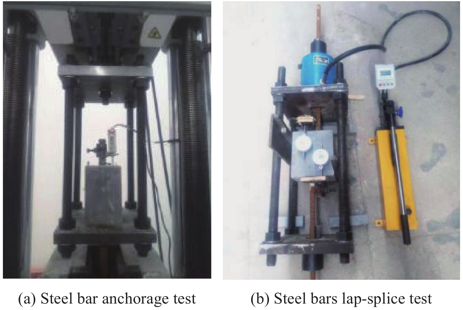
钢筋直接拔出锚固试验加载装置如图2(a)所示,钢筋锚固试验在100 t万能试验机上进行,采用位移控制加载,速率为0.5 mm/min。钢筋自由端安装位移计来测量自由端滑移量,通过TDS-530数据采集设备进行力和位移的采集。
钢筋搭接连接试验加载装置如2(b)所示,采用50 t锚杆拉拔仪通过手动加载对钢筋施加拉拔力,通过压力数显表人工读取拉力的大小;通过百分表来测量钢筋自由端与试块的相对滑移量;采用KD7016程控静态应变仪人工读取箍筋的应变。由于钢筋搭接连接试件两根钢筋不同轴,拉拔时会产生弯矩造成试件的转动,试块两侧放置限位钢垫块平衡弯矩。
2. 试验结果与分析
试件加载过程中的最大荷载称为极限荷载Pu,钢筋自由端出现滑移时的荷载称为滑移荷载Ps,屈服荷载Py实际是钢筋发生屈服时的荷载,各荷载值如表1所示。图3为各类型试件的极限荷载随锚固或搭接长度的变化关系,可以发现大部分试件的钢筋均发生屈服,一些试件的极限荷载接近甚至达到钢筋的极限受拉承载力。总体上,试件的极限荷载与钢筋锚固或搭接长度近似呈线性关系。
![]() 图 3 钢筋/UHPC锚固或搭接试件极限荷载-埋长曲线Figure 3. Ultimate load versus embedment length curves of anchorage and pull out lap-splice specimens of steel bars in UHPC
图 3 钢筋/UHPC锚固或搭接试件极限荷载-埋长曲线Figure 3. Ultimate load versus embedment length curves of anchorage and pull out lap-splice specimens of steel bars in UHPC2.1 钢筋/UHPC锚固或搭接试件破坏模式
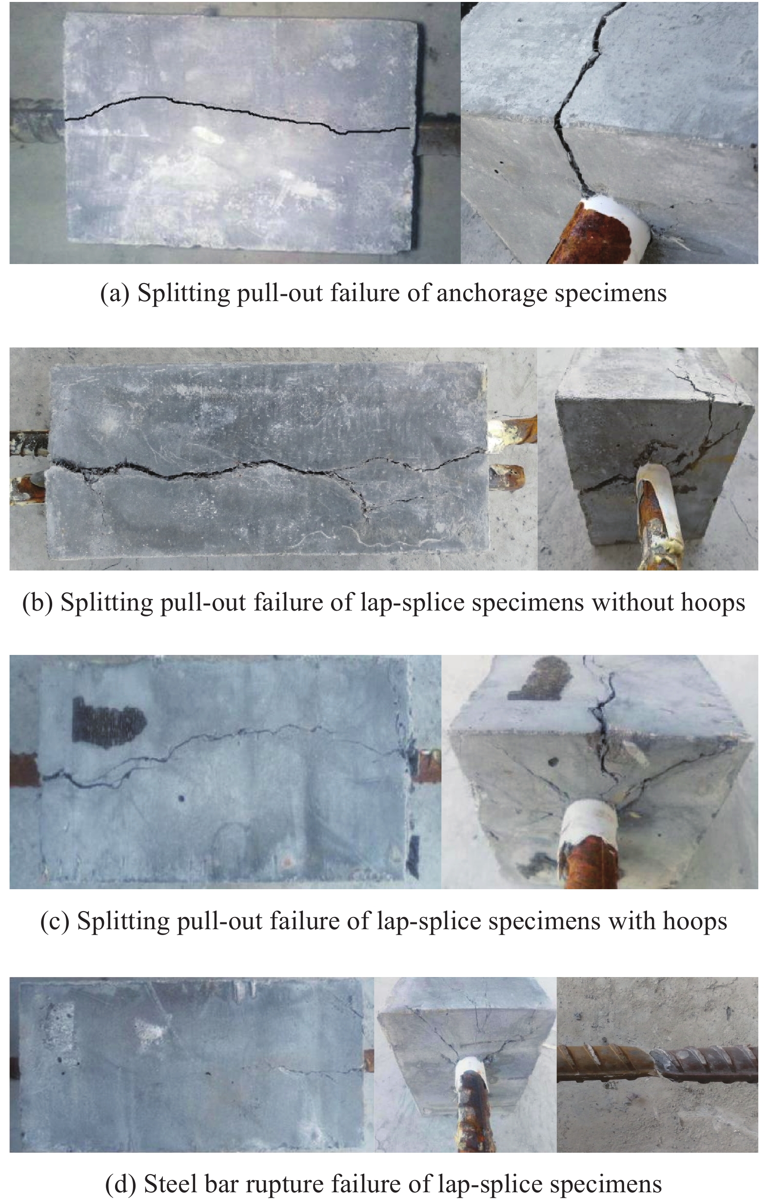
图4为钢筋/UHPC 锚固或搭接试件破坏形态。如图所示,本次试验共出现2种破坏模式,分别是劈裂拔出破坏和钢筋拉断破坏,破坏模式主要受搭接长度的影响,搭接长度越大,试件提供的抗拉拔合力越大,越容易发生钢筋拉断破坏。此外,纤维体积掺量和配箍率也对破坏模式有一定的影响。
![]() 图 4 钢筋/UHPC锚固或搭接试件破坏形态Figure 4. Failure patterns of anchorage and lap-splice specimens of steel bars in UHPC
图 4 钢筋/UHPC锚固或搭接试件破坏形态Figure 4. Failure patterns of anchorage and lap-splice specimens of steel bars in UHPC2.1.1 劈裂拔出破坏
所有的锚固试件和除LS-3-0-12d、LS-2-1.35-8d和LS-2-2.25-8d以外的搭接试件均发生劈裂拔出破坏。
对于发生劈裂拔出破坏未配箍筋的试件,加载初期荷载较小,试件无明显现象;加载至约0.25Pu时试件出现端面放射状裂缝,荷载由钢筋加载端向自由端传递,钢筋与UHPC锚固试件加载端的界面已开始局部滑移,自由端附近界面处于黏结状态;约0.36Pu时,因斜向压肢的推力造成两筋间的分离趋势,引起环向应力,试件出现侧面纵向劈裂裂缝,此时裂缝长度和宽度均较小;随着荷载的增加,裂缝不断延伸且加宽,同时又有新的端面放射状裂缝和侧面纵向裂缝产生,当钢筋自由端出现微小滑移时,各试件滑移荷载在0.83Pu~0.98Pu范围内,此时,加载端到自由端的化学黏结力逐步被削弱、丧失,拉力主要依靠钢筋肋部的机械咬合力与钢筋表面的摩擦力传递,此后荷载增长缓慢,裂缝继续延伸和加宽,钢筋自由端滑移增大;当纵向裂缝即将贯通时,裂缝宽度急剧增大,试件达到极限荷载Pu,发生纵向劈裂拔出破坏。钢筋锚固试件破坏见图4(a),钢筋搭接连接试件破坏见图4(b)。
对于发生劈裂拔出破坏配有箍筋的搭接试件,与未配箍筋的试件相比,其侧面纵向开裂荷载有所提高,约为0.4Pu,滑移荷载在0.60Pu~0.74Pu范围内,钢筋出现滑移后,荷载仍然会有显著的提高;达到Pu时,侧面纵向裂缝宽度增大,但未完全贯通,钢筋自由端滑移加快,钢筋逐渐从UHPC中拔出,如图4(c)所示。箍筋对UHPC的约束作用延迟了纵向裂缝的产生,纵向裂缝出现后,箍筋应变快速增大,产生较大的约束力,限制侧面纵向裂缝的加宽和延伸,达到Pu时侧面纵向裂缝未贯通。
2.1.2 钢筋拉断破坏
试件LS-3-0-12d纤维体积分数为3%,试件LS-2-1.35-8d和LS-2-2.25-8d的体积配箍率分别为1.35%和2.25%,三组试件均发生钢筋拉断破坏。与劈裂拔出破坏相比,加载初期试件端部也出现放射状裂缝,继续加载侧面出现纵向裂缝,但之后试件裂缝发展缓慢甚至停止发展,随着荷载的不断增大,最终发生钢筋拉断破坏,见图4(d),钢筋自由端始终未出现滑移。3%的纤维体积分数、1.35%和2.25%的配箍率可以有效提供侧向约束,使试件只需较短的搭接长度(分别为12d、8d、8d)就发生了钢筋的拉断破坏。
2.2 钢筋/UHPC平均黏结强度影响因素
钢筋/UHPC黏结应力沿锚固或搭接长度分布不均匀,且长度越大黏结应力分布越不均匀。采用钢筋/UHPC平均黏结应力来评估其黏结性能,计算公式如下:
τ=PπdL (1) 式中:P为对拉荷载;d为钢筋直径;L为锚固或搭接长度。对应于发生黏结破坏的应力称为平均黏结强度。
2.2.1 钢筋埋置长度的影响
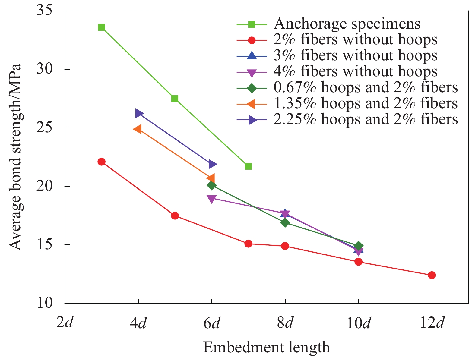
随着钢筋埋置长度的增大,钢筋拉拔应力由加载端向自由端传递的路径随之增大,可以延迟自由端的钢筋/UHPC黏结破坏,进而增大钢筋的极限荷载,如图3所示。但由于实际黏结应力分布不均匀,靠近加载端的黏结应力大,远离加载端的黏结应力小,增大埋置长度使远离加载端应力较小的部分变长了,因此,平均黏结应力随之减小,如图5所示。
![]() 图 5 钢筋/UHPC平均黏结强度与埋置长度关系Figure 5. Average bond strength versus embedded length of steel bars/UHPC
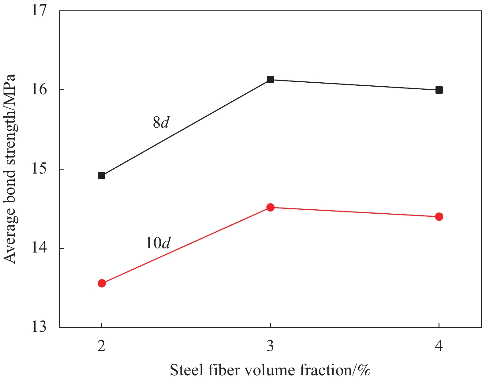
图 5 钢筋/UHPC平均黏结强度与埋置长度关系Figure 5. Average bond strength versus embedded length of steel bars/UHPC2.2.2 钢纤维掺量的影响
图6展示了钢筋/UHPC 平均黏结强度与钢纤维体积分数关系。如图所示,钢纤维体积分数由2%提高到3%,在8d和10d的搭接长度时,平均黏结强度分别提高了8.0%和6.7%。钢纤维在基体中乱向分布,阻止了硬化过程中微裂纹的产生,在受力过程中,钢纤维会阻挠裂纹的扩展,迫使其改变方向,缓冲裂缝尖端处的应力集中,从而起到阻裂的作用[17]。有效地约束了UHPC,抑制了劈裂裂缝的发展,提高了钢筋与UHPC的黏结强度[24]。钢纤维体积分数由3%提高到4%,在8d和10d的搭接长度时,平均黏结强度出现了略微降低,分别降低了0.80%和0.83%,其原因可能是钢纤维掺量增大,影响了UHPC的和易性和钢纤维的分散性,导致UHPC的密实度降低,降低了钢筋/UHPC黏结性能。
![]() 图 6 钢筋/UHPC平均黏结强度与钢纤维体积分数关系Figure 6. Average bond strength versus fibers fraction of steel bars/UHPC
图 6 钢筋/UHPC平均黏结强度与钢纤维体积分数关系Figure 6. Average bond strength versus fibers fraction of steel bars/UHPC2.2.3 配箍率的影响
试验过程中记录了每一级荷载作用下的箍筋应变,如图7所示,试件加载初期箍筋应变值较小,呈线性缓慢增长;随着荷载增加,试件内部出现裂缝,箍筋应变迅速增长,曲线斜率变大,达到极限荷载时,大部分箍筋达到屈服,强度得到充分发挥。
![]() 图 7 钢筋/UHPC搭接试件箍筋应变-荷载曲线Figure 7. Stirrup strains versus loads curves of steel bars lap-splice UHPC specimens
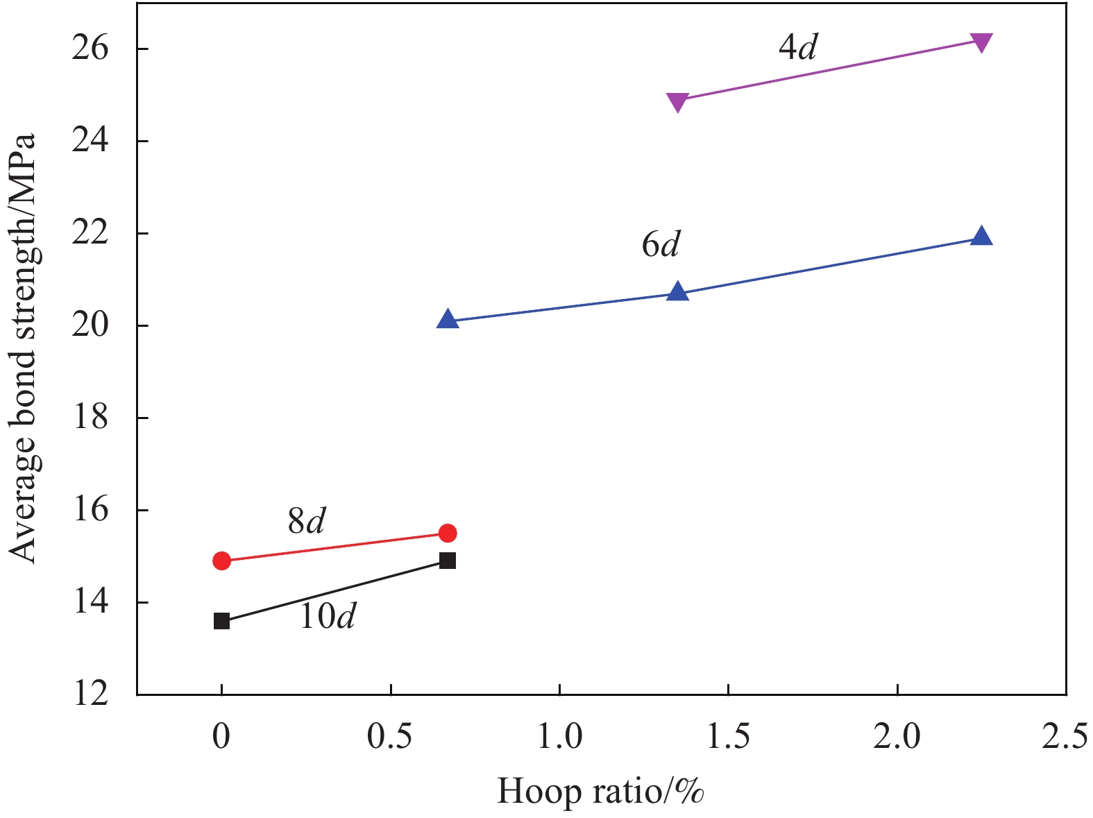
图 7 钢筋/UHPC搭接试件箍筋应变-荷载曲线Figure 7. Stirrup strains versus loads curves of steel bars lap-splice UHPC specimens配箍率对平均黏结强度的影响规律见图8,随着配箍率的增大平均黏结强度随之增大,箍筋可以对UHPC形成有效的约束,使钢筋周围UHPC处于多轴受压应力状态[25],钢筋之间斜向压肢的推力造成两筋间的分离趋势,会引起环向应力,箍筋可以抵消环向分力,有效抑制试件的纵向劈裂,进而提高黏结强度。
![]() 图 8 钢筋/UHPC平均黏结强度与配箍率关系Figure 8. Average bond strength versus stirrup ratio curves of steel bars/UHPC
图 8 钢筋/UHPC平均黏结强度与配箍率关系Figure 8. Average bond strength versus stirrup ratio curves of steel bars/UHPC3. 钢筋/UHPC锚固及搭接黏结强度计算
3.1 钢筋/UHPC锚固黏结强度
参考普通混凝土钢筋搭接强度拟合公式的形式[20],本文搜集了文献[15-17]中的钢筋/UHPC锚固试验数据,如表4所示,并根据本文的试验结果,拟合得到考虑钢筋直径、锚固长度、保护层厚度、纤维体积掺量和抗压强度影响的锚固黏结强度计算公式:
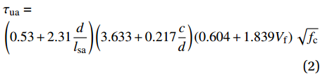
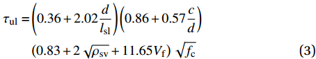
表 4 钢筋/UHPC锚固和对拉拔出搭接试件试验数据Table 4. Test data of anchorage specimens and pull out lap-splice specimens of steel bars in UHPCReference Notation d/mm L/mm c/mm ρsv fcu/MPa Vf τut/MPa Anchorage specimen [15] φ14-50 14 50 68 0 147.78 0.023 37.07 φ15-50 16 50 67 0 147.78 0.023 33.28 φ16-50 18 50 66 0 147.78 0.023 29.87 φ17-50 18 75 66 0 147.78 0.023 28.94 [16] H1-LZ-8-24 8 24 71 0 121.77 0.02 55.3 H1-LZ-8-32 8 32 71 0 121.77 0.02 45.7 H1-LZ-10-30 10 30 70 0 121.77 0.02 46.1 H1-LZ-10-40 10 40 70 0 121.77 0.02 42.9 H2-LZ-16-48 16 48 67 0 132.39 0.02 52.7 H2-LZ-16-64 16 64 67 0 132.39 0.02 42.9 H2-LZ-16-80 16 80 67 0 132.39 0.02 34.1 H2-LZ-18-54 18 54 66 0 132.39 0.02 55 H2-LZ-18-72 18 72 66 0 132.39 0.02 42.3 H3-LZ-6-18 6 18 72 0 153.09 0.03 51.1 H3-LZ-8-24 8 24 71 0 153.09 0.03 70.5 H3-LZ-8-32 8 32 71 0 153.09 0.03 52.8 H3-LZ-10-30 10 30 70 0 153.09 0.03 62.2 H2-NZ-16-12 16 48 12 0 132.39 0.02 31.1 H2-NZ-16-22 16 48 22 0 132.39 0.02 36 H2-NZ-16-32 16 48 32 0 132.39 0.02 41.9 H2-NZ-16-42 16 48 42 0 132.39 0.02 47.7 H2-NZ-16-52 16 48 52 0 132.39 0.02 48.8 H2-NZ-16-62 16 48 62 0 132.39 0.02 52.8 H3-LP-8-10 8 40 10 0 153.09 0.03 29.9 H3-LP-8-15 8 40 15 0 153.09 0.03 29.1 [17] P0.0 16 50 67 0 79.81 0 29.7 P0.5 16 50 67 0 92.27 0.005 31.18 P1.0 16 50 67 0 114.30 0.01 32.05 P1.5 16 50 67 0 117.02 0.015 36.72 P2.0 16 50 67 0 128.58 0.02 38.12 Lap-splice specimen [23] L100-R100-D1-S0 20 100 45 0 96.03 0.02 17.14 L100-R100-D1-S34 20 100 45 0.0034 96.03 0.02 18 L100-R100-D1-S75 20 100 45 0.0075 96.03 0.02 19.03 L100-R120-D1-S0 20 100 45 0 117.36 0.02 18.95 L100-R120-D1-S34 20 100 45 0.0034 117.36 0.02 19.9 L100-R120-D1-S75 20 100 45 0.0075 117.36 0.02 21.04 L100-R150-D1-S0 20 100 45 0 141.39 0.02 20.36 L100-R150-D1-S34 20 100 45 0.0034 141.39 0.02 22.12 L100-R150-D1-S75 20 100 45 0.0075 141.39 0.02 23.35 L150-R100-D1-S34 20 150 45 0.0034 96.03 0.02 17.52 L150-R120-D1-S34 20 150 45 0.0034 96.03 0.02 19.18 L200-R100-D1-S34 20 200 45 0.0034 96.03 0.02 14.75 L200-R100-D1-S34 20 200 45 0.0034 96.03 0.02 13.74 Notes: d—Steel bar diameter; L—Embedment length; c—Thickness of UHPC cover; ρsv—Hoop ratio; fcu—Compressive strength of cube; Vf—Fibre volume fraction; τut—Test value of ultimate average bond strength. τua=(0.53+2.31dlsa)(3.633+0.217cd)(0.604+1.839Vf)√fc (2) 回归公式的相关系数为0.97;适用范围:相对保护层厚度c/d在[1,5],纤维体积掺量Vf在[0,0.03],抗压强度fc在[80,150]。式中:τua为钢筋/UHPC极限锚固黏结强度;d为钢筋直径;lsa为锚固长度;c为保护层厚度,当相对保护层厚度c/d大于5时,取为5;fc为UHPC单轴抗压强度。
3.2 钢筋/UHPC搭接黏结强度
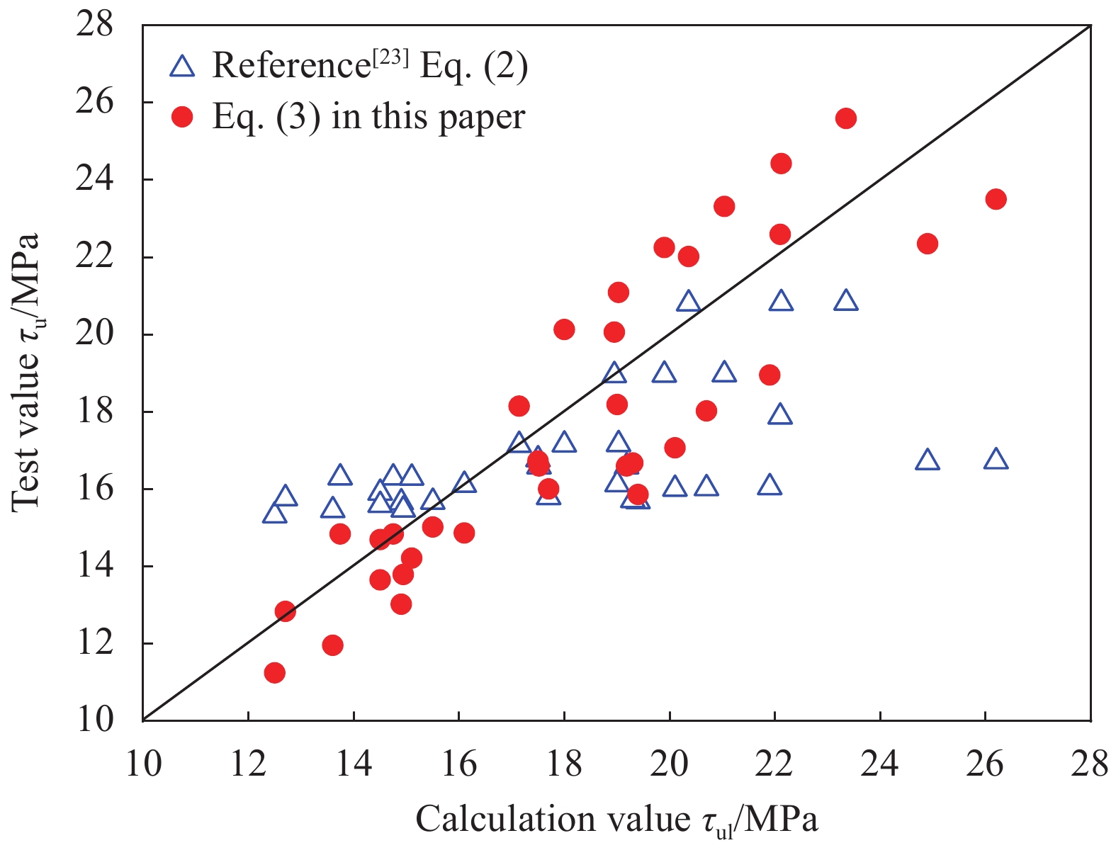
文献[23]通过试验数据拟合回归了钢筋搭接黏结强度公式,但没有考虑UHPC中纤维掺量因素的影响,本试验进一步丰富了搭接试验的数据,对文献[23]的公式进行验证,发现与试验值具有较大误差,如图9所示。因此,结合本文试验结果并参考文献[23]的试验数据(表4),拟合得到考虑钢筋直径、搭接长度、保护层厚度、配箍率、纤维体积掺量和抗压强度影响的钢筋/UHPC搭接黏结强度计算公式:
![]() 图 9 钢筋搭接强度拟合公式计算值与试验值对比Figure 9. Comparison between the calculated value and the test value of the fitting formula of the steel lap-splice strength
图 9 钢筋搭接强度拟合公式计算值与试验值对比Figure 9. Comparison between the calculated value and the test value of the fitting formula of the steel lap-splice strengthτul=(0.36+2.02dlsl)(0.86+0.57cd)(0.83+2√ρsv+11.65Vf)√fc (3) 回归公式的相关系数为0.99,适用范围:相对保护层厚度c/d在[1.8,2.8],配箍率ρsv在[0,0.0225],纤维体积掺量Vf在[0.02,0.04],抗压强度fc在[90,150]。式中:τul为钢筋/UHPC极限搭接黏结强度;lsl为搭接长度;ρsv为试件配箍率。拟合公式计算值与试验值吻合良好,如图9所示。
为了验证拟合公式的有效性,对文献[6]和[18]的梁式搭接试件的黏结强度进行计算并与试验结果进行对比,如表5所示,计算值与试验值比值的平均值为1.15,变异系数为0.29,与梁式试件试验结果吻合较好。
表 5 钢筋/UHPC搭接梁式试件黏结强度拟合公式验证Table 5. Verification of the fitting formula for lap-splice bond strength of beam lap-splice steel bars/UHPC specimensReference Notation d/mm L/mm c/mm fc/MPa Vf τut/MPa τuf/MPa τuf/τut Beam lap-splice specimen [6] 1-12-25-L 25 300 45 130 0.03 10.8 13.40 1.26 2-12-25-L 25 300 45 130 0.03 9.8 13.40 1.39 1-18-25-L 25 450 45 130 0.03 6.8 11.98 1.96 1-12-35-L 35 420 45 130 0.03 9.8 11.32 1.15 1-18-35-L 35 630 45 130 0.03 6.11 10.12 1.81 1-6-25-L 25 150 45 130 0.03 19.6 17.67 0.74 1-6-25-L1 25 150 45 130 0.03 19.6 17.67 0.74 1-12-25-L1 25 300 45 130 0.03 9.8 13.40 1.39 1-6-35-L 35 210 45 130 0.03 16.23 14.92 0.74 1-6-35-L½ 35 210 45 130 0.03 12.32 14.92 0.97 1-12-35-L½ 35 420 45 130 0.03 9.16 11.32 1.24 [18] 25-12-L-1% 25 300 25 125 0.01 9.5 8.00 1.04 25-12-L-2% 25 300 25 124 0.02 10.4 8.94 0.94 25-12-L-3% 25 300 25 114 0.03 10.5 9.51 0.90 25-12-R-3% 25 300 25 114 0.03 10 9.51 0.94 35-18-L-3% 35 630 35 114 0.03 8.2 8.50 1.13 35-18-R-3% 35 630 35 114 0.03 7.2 8.50 1.28 Average value 1.15 Variation coefficient 0.29 Notes: fc—Uniaxial compressive strength; τut—Test value of ultimate average bond strength; τuf—Value of ultimate average bond strength calculated by the Eq. (3). 4. 钢筋/UHPC临界锚固及搭接长度计算
定义钢筋达到屈服强度fy时,钢筋从UHPC中不被拨出所需的最小锚固和搭接长度分别为临界屈服锚固长度lsay和临界屈服搭接长度lsly;钢筋达到极限强度fu时,钢筋从UHPC中不被拨出所需的最小锚固和搭接长度分别为临界极限锚固长度lsau和临界极限搭接长度lslu。由图3可知,各类型试件的极限荷载随锚固或搭接长度的变化趋势近似为线性,因此,各类试件的临界屈服锚固长度lsayt或搭接长度lslyt (合称为临界屈服长度lsyt)以及临界极限锚固长度lsaut或搭接长度lslut (合称为临界极限长度lsut)可按线性规律近似确定,如表6和图10所示。随着纤维体积掺量和配箍率的增大,临界屈服和极限长度逐渐减小。
表 6 钢筋/UHPC锚固和搭接长度试验值与计算值Table 6. Test values and calculated values of development length and splice length of steel bars/UHPCType Minimum anchorage or lap length of steel bar yield Minimum anchorage or lap length of steel bar rupture lsyACI lsyGB lsys lsyf lsyt lsuACI lsuGB lsus lsuf lsut Anchorage specimen 28.6d 11.2d 5.3d 3.7d 3.6d 39.1d 15.3d 7.2d 6.6d 7.1d 2.25vol% hoops 20.9d 17.9d 10.5d 5.8d 4.5d 28.6d 24.4d 14.4d 10.1d 7.6d 1.35vol% hoops 20.9d 17.9d 10.5d 6.4d 4.9d 28.6d 24.4d 14.4d 11.0d 8.1d 0.67vol% hoops 20.9d 17.9d 10.5d 7.1d 4.8d 28.6d 24.4d 14.4d 11.9d 10.6d 4vol% fibers 28.9d 17.6d 10.6d 6.5d 5.8d 39.4d 24.0d 14.5d 11.1d 13.2d 3vol% fibers 28.3d 16.4d 10.4d 7.5d — 38.7d 22.4d 14.3d 12.5d 12.1d 2vol% fibers 29.0d 17.9d 10.5d 9.3d 7.3d 39.7d 24.4d 14.4d 15.0d 12.6d Notes: lsyACI, lsyGB, lsys and lsyf—Minimum anchorage or lap length of steel bar yield calculated by the ACI 318—19[27], GB 50010—2010[26], simplified algorithm and fitting formula, respectively; lsuACI, lsuGB, lsus, and lsuf—Minimum anchorage or lap length of steel bar rupture calculated by the ACI 318—19[27], GB 50010—2010[26], simplified algorithm and fitting formula, respectively; lsyt—Test value of minimum anchorage or lap length of steel bar yield; lsut—Test value of minimum anchorage or lap length of steel bar rupture. ![]() 图 10 不同类型钢筋/UHPC锚固或搭接试件的临界长度计算值与试验值Figure 10. Test and calculation values of critical length for different types of anchorage and pull out lap splice steel bars/UHPC specimens
图 10 不同类型钢筋/UHPC锚固或搭接试件的临界长度计算值与试验值Figure 10. Test and calculation values of critical length for different types of anchorage and pull out lap splice steel bars/UHPC specimens4.1 规范中钢筋/UHPC的锚固和搭接长度的计算
4.1.1 GB 50010—2010规范[26]的锚固和搭接长度计算
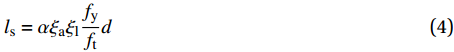
《混凝土结构设计规范》GB 50010—2010[26]中规定受拉钢筋的锚固和搭接长度按下式进行计算:
ls=αξaξlfyftd (4) 式中:α为钢筋的外形系数,考虑钢筋的表面类型对黏结强度的影响,对本文钢筋取0.14;ξa为锚固或搭接长度修正系数,主要考虑了钢筋直径大于25 mm,表面涂有环氧树脂,有施工扰动,实配钢筋面积大于计算钢筋面积以及保护层厚度大于3d或5d等情况的影响;ξ1为纵向受拉钢筋搭接长度修正系数,主要考虑了纵向搭接钢筋接头面积百分率,对本文试件取1.6,对于锚固试件取1.0。
4.1.2 ACI 318—19规范[27]搭接长度的算法
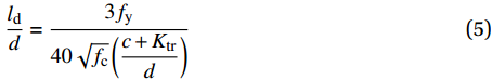
美国规范ACI 318—19[27]根据表7将搭接接头分为A、B两类,其中基本的锚固或搭接长度按下式计算:
As,p/As,r Maximum percent of As spliced
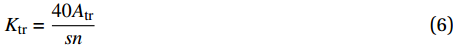
within required lap length/%Splice type Lap splice lengths ls ≥2 50 A Greater of: 1.0ld and 304.8 mm 100 B Greater of: 1.3ld and 304.8 mm <2 All cases B Note: As,p/As,r—Ratio of area of reinforcement provided to area of reinforcement required by analysis at splice location. ldd=3fy40√fc(c+Ktrd) (5) Ktr=40Atrsn (6) 式中:为避免发生钢筋拔出破坏:规定
(c+Ktr)/d⩽ 2.5 ;f为钢筋应力;fc混凝土圆柱体抗压强度,由于缺少抗压强度69 MPa以上的试验数据,限定\sqrt {{f_{\rm{c}}}} \leqslant 8.3 ,但Azizinamini等[28]和Hamad等[29]均认为这条限定并不合理;c为保护层厚度;d为钢筋直径;Atr为垂直于劈裂面的横向钢筋面积;s为横向钢筋间距;n为搭接钢筋数量。由公式可以看出美国规范考虑了混凝土抗压强度、保护层厚度、钢筋直径和箍筋对搭接长度的影响。本文搭接接头按B类接头进行计算。分别采用GB 50010—2010规范[26]及ACI 318—19规范[27]对钢筋/UHPC锚固和搭接长度进行计算,如表6和图10所示,对比试验结果可知:两规范计算的临界锚固和搭接长度偏于保守,尤其对于无箍筋的试件,美国ACI 318—19规范[27]的计算结果过于保守。
4.2 钢筋/UHPC临界锚固、搭接长度拟合公式
4.2.1 临界锚固长度拟合公式
结合式(1)和式(2),可以推出钢筋/UHPC的锚固长度计算公式:
\frac{{{l_{{\rm{sa}}}}}}{d} = \frac{f}{{2.22\left(0.86 + 0.57\dfrac{c}{d}\right)(0.83 + 11.56{V_{\rm{f}}})\sqrt {{f_{\rm{c}}}} }} - 5.61 (7) 式中:
{l_{{\rm{sa}}}}/d 称为相对锚固长度。f取钢筋屈服强度fy时,得临界屈服锚固长度lsayf;当f取钢筋极限强度fu时,得到临界极限锚固长度lsauf。4.2.2 临界搭接长度拟合公式
同样结合式(1)和式(3),可以推出钢筋/UHPC搭接长度计算公式:
\begin{split} &\frac{{{l_{{\rm{sl}}}}}}{d} =\\ &\dfrac{f}{{1.44\left(0.86 + 0.57\dfrac{c}{d}\right)(0.83 + 2\sqrt {{\rho _{{\rm{sv}}}}} + 11.65{V_{\rm{f}}})\sqrt {{f_{\rm{c}}}} }} - 5.61 \end{split} (8) 式中:f取钢筋屈服强度fy时,得临界屈服搭接长度lslyf;f取钢筋极限强度fu时,得到临界极限搭接长度lsauf。
临界锚固和搭接长度拟合公式计算值如表6和图10所示,可知拟合公式计算值与试验值吻合良好。
4.3 钢筋/UHPC临界搭接长度简化算法
为便于工程实际应用,参考GB 50010—2010规范[26]的算法,提出钢筋/UHPC临界锚固和搭接长度简化计算方法。钢筋搭接因仅有部分周径参与力的传递,因此,钢筋的搭接长度较锚固长度长[30]。GB 50010—2010规范[26]以锚固长度为基准,对于纵向搭接钢筋接头面积百分率为25%、50%和100%的情况,搭接长度分别取1.2、1.4和1.6倍的锚固长度。
4.3.1 钢筋/UHPC临界锚固长度简化计算公式
式(4)实际上是根据受力平衡条件建立的锚固长度计算公式
{l_{\rm{s}}} = \dfrac{{{f_{\rm{y}}}d}}{{4{\tau _{\rm{u}}}}} 的变形,采用混凝土的单轴抗拉强度ft替代τu来表征混凝土强度对锚固长度的影响,式(4)中的外形系数\alpha = \dfrac{{{f_{\rm{t}}}}}{{4{\tau _{\rm{u}}}}} 。原海燕[31]对比了UHPC与普通C40混凝土的各项力学性能,UHPC单轴抗拉强度为普通C40混凝土的1.5倍,抗压强度和极限黏结强度均约为普通混凝土的3倍。因此,对于UHPC采用其抗压强度替代τu来表征UHPC强度对锚固长度的影响较为合理。此时,定义外形系数{\alpha _{\rm{u}}} = \dfrac{{\sqrt {{f_{\rm{c}}}} }}{{4{\tau _{\rm{u}}}}} ,通过对本文试验及参考文献[15-17]的数据进行分析计算得αu的取值范围在0.04~0.12之间,因此偏安全的取为0.12。得到钢筋/UHPC锚固长度计算公式:{l_{\rm{s}}} = {\alpha _{\rm{u}}}\frac{f}{{\sqrt {{f_{\rm{c}}}} }}d (9) 式中:f取钢筋屈服强度fy时得临界屈服锚固长度lsay,f取钢筋极限强度fu时得临界极限锚固长度lsau;fc为UHPC单轴抗压强度。
4.3.2 临界锚固长度与搭接长度对比分析
钢筋搭接因仅有部分周径参与力的传递,因此,钢筋的搭接长度较锚固长度长。本文采用直径25 mm的钢筋,相同纤维体积分数(2%)、保护层厚度(45 mm)和UHPC抗压强度(103.6 MPa)且未配箍筋的情况下,分别进行了3d、5d和7d埋置长度的锚固和搭接试验,由表6和图10可知钢筋/UHPC临界屈服锚固和搭接长度分别为3.6d和7.3d,临界极限锚固和搭接长度分别为7.1d和12.6d,可得UHPC中变形钢筋的临界搭接长度约为其临界锚固长度的2倍,验证了文献[23]所推得的结论。因此,钢筋/UHPC搭接长度可由式(9)计算出的锚固长度乘以2得到。
简化算法计算结果如表6和图10所示,式(9)未考虑纤维体积掺量和配箍率的影响,计算结果较为保守,但相比于GB 50010—2010规范[26]及ACI 318—19规范[27]的计算值较为准确。
文献[6]中直径25 mm的钢筋在梁跨中搭接于抗压强度130 MPa、纤维体积分数为3%的UHPC中,保护层厚度为30 mm且未配箍筋,在搭接长度为12d时,单调荷载作用下未发生搭接破坏,分别采用拟合公式和简化算法计算的临界极限搭接长度为12.7d和13.6d,与试验结果相比较为吻合且偏于安全。
5. 结 论
通过21组钢筋搭接对拉拔出试验和3组钢筋直接拔出锚固试验,并参考相关文献数据,得出以下结论:
(1)钢筋搭接试验主要出现劈裂拔出破坏和钢筋拉断破坏2种破坏模式,增大搭接长度和配箍率以及适当增大纤维掺量均有利于试件由劈裂拔出破坏变为钢筋拉断破坏;
(2)试验得出各类型试件的临界屈服和极限搭接长度,对直径为25 mm的HRB400带肋钢筋,在抗压强度为110.1 MPa、纤维体积分数为2%的超高性能混凝土(UHPC)中,保护层厚度为45 mm且未配箍筋时,其临界屈服和极限搭接长度分别为7.3d和12.6d (d为钢筋直径),增加配箍率和适当增大纤维掺量均能减小钢筋/UHPC临界搭接长度;
(3)随搭接长度的增大,钢筋/UHPC平均黏结强度减小;钢纤维掺量的增大及配箍率的增大,提高了箍筋对UHPC的约束作用,有效限制了试件的纵向劈裂,黏结强度随之增大;
(4)采用中国GB 50010—2010规范[26]和ACI 318—19规范[27]计算的钢筋/UHPC锚固和搭接长度与试验结果相比均过于保守。参考相关文献的试验数据,并结合本文的试验结果,拟合得到钢筋锚固试件、钢筋搭接试件的平均黏结强度计算公式及临界锚固和搭接长度计算公式,且采用梁式搭接试验的结果对钢筋/UHPC黏结强度拟合公式进行验证,结果较为吻合。参考中国规范的算法建立了钢筋/UHPC临界锚固和搭接长度简化算法,未考虑纤维掺量和配箍率的影响,计算结果较为保守,相比于GB 50010—2010规范[26]及ACI 318—19规范[27]的计算值较为准确。
-
![]()
图 1 钢筋/超高性能混凝土(UHPC)搭接试件尺寸及制作(单位:mm)
Figure 1. Size and fabrication of steel bars/ultra high performance concrete (UHPC) lap-splice specimens (Unit: mm)
![]()
图 3 钢筋/UHPC锚固或搭接试件极限荷载-埋长曲线
Figure 3. Ultimate load versus embedment length curves of anchorage and pull out lap-splice specimens of steel bars in UHPC
![]()
图 4 钢筋/UHPC锚固或搭接试件破坏形态
Figure 4. Failure patterns of anchorage and lap-splice specimens of steel bars in UHPC
![]()
图 5 钢筋/UHPC平均黏结强度与埋置长度关系
Figure 5. Average bond strength versus embedded length of steel bars/UHPC
![]()
图 6 钢筋/UHPC平均黏结强度与钢纤维体积分数关系
Figure 6. Average bond strength versus fibers fraction of steel bars/UHPC
![]()
图 7 钢筋/UHPC搭接试件箍筋应变-荷载曲线
Figure 7. Stirrup strains versus loads curves of steel bars lap-splice UHPC specimens
![]()
图 8 钢筋/UHPC平均黏结强度与配箍率关系
Figure 8. Average bond strength versus stirrup ratio curves of steel bars/UHPC
![]()
图 9 钢筋搭接强度拟合公式计算值与试验值对比
Figure 9. Comparison between the calculated value and the test value of the fitting formula of the steel lap-splice strength
![]()
图 10 不同类型钢筋/UHPC锚固或搭接试件的临界长度计算值与试验值
Figure 10. Test and calculation values of critical length for different types of anchorage and pull out lap splice steel bars/UHPC specimens
表 1 钢筋锚固和搭接钢筋/UHPC试件参数及试验结果
Table 1 Parameters and test results of anchorage and lap-splice steel bars/UHPC specimens
Number Notation Vf/% {\rho _{{\rm{sv}}}}/% L fcu/MPa fc/MPa Py/kN Ps/kN Pu/kN τmt/MPa Failure mode 1 A-2-0-3d 2 0 3d 117.1 103.6 — 190.4 197.6 33.6 SPF 2 A-2-0-5d 5d 218.6 265.2 269.5 27.5 SPF 3 A-2-0-7d 7d 220.4 284.6 298.1 21.7 SPF 4 LS-2-0-3d 2 0 3d 117.1 103.6 — 111.9 130.2 22.1 SPF 5 LS-2-0-5d 5d — 143.4 171.8 17.5 SPF 6 LS-2-0-7d 7d — 173.3 208.3 15.1 SPF 7 LS-2-0-8d 2 0 8d 110.1 100.9 219.1 223.4 234.2 14.9 SPF 8 LS-2-0-10d 10d 215.6 246.9 266.0 13.6 SPF 9 LS-2-0-12d 12d 217.6 272.8 293.7 12.5 SPF 10 LS-3-0-8d 3 0 8d 116.6 105.5 217.2 245.8 253.2 16.1 SPF 11 LS-3-0-10d 10d 219.1 265.7 284.8 14.5 SPF 12 LS-3-0-12d 12d 216.3 285.9 298.8 12.7 RF 13 LS-4-0-6d 4 0 6d 112 102 217.1 201.3 224.0 19.0 SPF 14 LS-4-0-8d 8d 215.3 244.9 250.1 16.0 SPF 15 LS-4-0-10d 10d 217.1 276.3 282.2 14.4 SPF 16 LS-2-0.67-6d 2 0.67 6d 110.1 100.9 218.2 164.9 236.6 20.1 SPF 17 LS-2-0.67-8d 8d 218.4 180.5 243.5 15.5 SPF 18 LS-2-0.67-10d 10d 215.8 201.3 292.9 14.94 SPF 19 LS-2-1.35-4d 2 1.35 4d 110.1 100.9 — 122.6 195.3 24.9 SPF 20 LS-2-1.35-6d 6d 218.8 146.6 244.3 20.7 SPF 21 LS-2-1.35-8d 8d 219.4 202.4 304.2 19.4 RF 22 LS-2-2.25-4d 2 2.25 4d 110.1 100.9 — 128.1 206.0 26.2 SPF 23 LS-2-2.25-6d 6d 219.4 167.7 257.9 21.9 SPF 24 LS-2-2.25-8d 8d 214.5 216.0 302.8 19.3 RF Notes: d—Steel bar diameter; Vf—Fibre volume fraction; ρsv—Hoop ratio; L—Embedment length; fcu—Compressive strength of cube; fc—Compressive strength of prism; Py, Ps and Pu—Yield, slippage and peak loads in the test, respectively; τmt—Mean bond strength measured in the test; SPF and RF represent the splitting pull-out failure and steel bar rupture failure, respectively. The “A” and “LS” in notation system—Anchorage specimen and lap-splice specimen, respectively. The figures in the second, third and fourth symbol—Fibre volume fraction (%), stirrup ratio (%) and embedment length, respectively. For example, the notation of “LS-2-0-3d”—Splice specimen with 2% of fibre volume fraction, 0% of stirrup ratio and 3 bar diameters embedment.  下载: 导出CSV
表 2 UHPC配合比
Table 2 Mix proportions of UHPC
Number Water to
binder ratioCement Fly
ashSilica
fumeMineral
powderQuartz
sandSuperplasticizer Volume fraction of
steel fiber Vf1 0.18 1.00 0.30 0.30 0.30 1.3 0.05 0.02 2 0.18 1.00 0.30 0.30 0.30 1.3 0.05 0.03 3 0.18 1.00 0.30 0.30 0.30 1.3 0.05 0.04
下载: 导出CSV
表 3 钢筋力学性能
Table 3 Mechanical properties of steel bars
Diameter/mm Strength grade Yield strength/MPa Ultimate strength/MPa 25 HRB400 447 611 18 HRB400 436 608 8 HPB300 364 540
下载: 导出CSV
表 4 钢筋/UHPC锚固和对拉拔出搭接试件试验数据
Table 4 Test data of anchorage specimens and pull out lap-splice specimens of steel bars in UHPC
Reference Notation d/mm L/mm c/mm ρsv fcu/MPa Vf τut/MPa Anchorage specimen [15] φ14-50 14 50 68 0 147.78 0.023 37.07 φ15-50 16 50 67 0 147.78 0.023 33.28 φ16-50 18 50 66 0 147.78 0.023 29.87 φ17-50 18 75 66 0 147.78 0.023 28.94 [16] H1-LZ-8-24 8 24 71 0 121.77 0.02 55.3 H1-LZ-8-32 8 32 71 0 121.77 0.02 45.7 H1-LZ-10-30 10 30 70 0 121.77 0.02 46.1 H1-LZ-10-40 10 40 70 0 121.77 0.02 42.9 H2-LZ-16-48 16 48 67 0 132.39 0.02 52.7 H2-LZ-16-64 16 64 67 0 132.39 0.02 42.9 H2-LZ-16-80 16 80 67 0 132.39 0.02 34.1 H2-LZ-18-54 18 54 66 0 132.39 0.02 55 H2-LZ-18-72 18 72 66 0 132.39 0.02 42.3 H3-LZ-6-18 6 18 72 0 153.09 0.03 51.1 H3-LZ-8-24 8 24 71 0 153.09 0.03 70.5 H3-LZ-8-32 8 32 71 0 153.09 0.03 52.8 H3-LZ-10-30 10 30 70 0 153.09 0.03 62.2 H2-NZ-16-12 16 48 12 0 132.39 0.02 31.1 H2-NZ-16-22 16 48 22 0 132.39 0.02 36 H2-NZ-16-32 16 48 32 0 132.39 0.02 41.9 H2-NZ-16-42 16 48 42 0 132.39 0.02 47.7 H2-NZ-16-52 16 48 52 0 132.39 0.02 48.8 H2-NZ-16-62 16 48 62 0 132.39 0.02 52.8 H3-LP-8-10 8 40 10 0 153.09 0.03 29.9 H3-LP-8-15 8 40 15 0 153.09 0.03 29.1 [17] P0.0 16 50 67 0 79.81 0 29.7 P0.5 16 50 67 0 92.27 0.005 31.18 P1.0 16 50 67 0 114.30 0.01 32.05 P1.5 16 50 67 0 117.02 0.015 36.72 P2.0 16 50 67 0 128.58 0.02 38.12 Lap-splice specimen [23] L100-R100-D1-S0 20 100 45 0 96.03 0.02 17.14 L100-R100-D1-S34 20 100 45 0.0034 96.03 0.02 18 L100-R100-D1-S75 20 100 45 0.0075 96.03 0.02 19.03 L100-R120-D1-S0 20 100 45 0 117.36 0.02 18.95 L100-R120-D1-S34 20 100 45 0.0034 117.36 0.02 19.9 L100-R120-D1-S75 20 100 45 0.0075 117.36 0.02 21.04 L100-R150-D1-S0 20 100 45 0 141.39 0.02 20.36 L100-R150-D1-S34 20 100 45 0.0034 141.39 0.02 22.12 L100-R150-D1-S75 20 100 45 0.0075 141.39 0.02 23.35 L150-R100-D1-S34 20 150 45 0.0034 96.03 0.02 17.52 L150-R120-D1-S34 20 150 45 0.0034 96.03 0.02 19.18 L200-R100-D1-S34 20 200 45 0.0034 96.03 0.02 14.75 L200-R100-D1-S34 20 200 45 0.0034 96.03 0.02 13.74 Notes: d—Steel bar diameter; L—Embedment length; c—Thickness of UHPC cover; ρsv—Hoop ratio; fcu—Compressive strength of cube; Vf—Fibre volume fraction; τut—Test value of ultimate average bond strength.
下载: 导出CSV
表 5 钢筋/UHPC搭接梁式试件黏结强度拟合公式验证
Table 5 Verification of the fitting formula for lap-splice bond strength of beam lap-splice steel bars/UHPC specimens
Reference Notation d/mm L/mm c/mm fc/MPa Vf τut/MPa τuf/MPa τuf/τut Beam lap-splice specimen [6] 1-12-25-L 25 300 45 130 0.03 10.8 13.40 1.26 2-12-25-L 25 300 45 130 0.03 9.8 13.40 1.39 1-18-25-L 25 450 45 130 0.03 6.8 11.98 1.96 1-12-35-L 35 420 45 130 0.03 9.8 11.32 1.15 1-18-35-L 35 630 45 130 0.03 6.11 10.12 1.81 1-6-25-L 25 150 45 130 0.03 19.6 17.67 0.74 1-6-25-L1 25 150 45 130 0.03 19.6 17.67 0.74 1-12-25-L1 25 300 45 130 0.03 9.8 13.40 1.39 1-6-35-L 35 210 45 130 0.03 16.23 14.92 0.74 1-6-35-L½ 35 210 45 130 0.03 12.32 14.92 0.97 1-12-35-L½ 35 420 45 130 0.03 9.16 11.32 1.24 [18] 25-12-L-1% 25 300 25 125 0.01 9.5 8.00 1.04 25-12-L-2% 25 300 25 124 0.02 10.4 8.94 0.94 25-12-L-3% 25 300 25 114 0.03 10.5 9.51 0.90 25-12-R-3% 25 300 25 114 0.03 10 9.51 0.94 35-18-L-3% 35 630 35 114 0.03 8.2 8.50 1.13 35-18-R-3% 35 630 35 114 0.03 7.2 8.50 1.28 Average value 1.15 Variation coefficient 0.29 Notes: fc—Uniaxial compressive strength; τut—Test value of ultimate average bond strength; τuf—Value of ultimate average bond strength calculated by the Eq. (3).
下载: 导出CSV
表 6 钢筋/UHPC锚固和搭接长度试验值与计算值
Table 6 Test values and calculated values of development length and splice length of steel bars/UHPC
Type Minimum anchorage or lap length of steel bar yield Minimum anchorage or lap length of steel bar rupture lsyACI lsyGB lsys lsyf lsyt lsuACI lsuGB lsus lsuf lsut Anchorage specimen 28.6d 11.2d 5.3d 3.7d 3.6d 39.1d 15.3d 7.2d 6.6d 7.1d 2.25vol% hoops 20.9d 17.9d 10.5d 5.8d 4.5d 28.6d 24.4d 14.4d 10.1d 7.6d 1.35vol% hoops 20.9d 17.9d 10.5d 6.4d 4.9d 28.6d 24.4d 14.4d 11.0d 8.1d 0.67vol% hoops 20.9d 17.9d 10.5d 7.1d 4.8d 28.6d 24.4d 14.4d 11.9d 10.6d 4vol% fibers 28.9d 17.6d 10.6d 6.5d 5.8d 39.4d 24.0d 14.5d 11.1d 13.2d 3vol% fibers 28.3d 16.4d 10.4d 7.5d — 38.7d 22.4d 14.3d 12.5d 12.1d 2vol% fibers 29.0d 17.9d 10.5d 9.3d 7.3d 39.7d 24.4d 14.4d 15.0d 12.6d Notes: lsyACI, lsyGB, lsys and lsyf—Minimum anchorage or lap length of steel bar yield calculated by the ACI 318—19[27], GB 50010—2010[26], simplified algorithm and fitting formula, respectively; lsuACI, lsuGB, lsus, and lsuf—Minimum anchorage or lap length of steel bar rupture calculated by the ACI 318—19[27], GB 50010—2010[26], simplified algorithm and fitting formula, respectively; lsyt—Test value of minimum anchorage or lap length of steel bar yield; lsut—Test value of minimum anchorage or lap length of steel bar rupture.
下载: 导出CSV
As,p/As,r Maximum percent of As spliced
within required lap length/%Splice type Lap splice lengths ls ≥2 50 A Greater of: 1.0ld and 304.8 mm 100 B Greater of: 1.3ld and 304.8 mm <2 All cases B Note: As,p/As,r—Ratio of area of reinforcement provided to area of reinforcement required by analysis at splice location.
下载: 导出CSV
-
[1] 中国国家标准化管理委员会. 活性粉末混凝土: CB/T 31387—2015[S]. 中国标准出版社, 2015 National Standardization Administration of China. Reactive powder concrete: CB/T 31387—2015[S]. China Standard Press, 2015 (in Chinese).
[2] YUAN J, GRAYBEAL B. Bond of reinforcement in ultra-high-performance concrete[J]. ACI Structural Journal,2015,112(6):851.
[3] GRAYBEAL B. Design and construction of field-cast UHPC connections[R]. United States: Federal Highway Administration, 2014.
[4] SHAFIEIFAR M, FARZAD M, AZIZINAMINI A. Alternative ABC connection utilizing UHPC[R]. Washington DC, United States: Transportation Research Board 96th Annual Meeting, 2017.
[5] AARUP B, JENSEN B C. Bond properties of high-strength fiber reinforced concrete[J]. Special Publication,1998,180:459-472.
[6] DAGENAIS M A, MASSICOTTE B. Tension lap splices strengthened with ultrahigh-performance fiber-reinforced concrete[J]. Journal of Materials in Civil Engineering,2014,27(7):04014206.
[7] GRAYBEAL B. Behavior of field-cast ultra-high performance concrete bridge deck connections under cyclic and static structural loading[R]. US: Department of Transportation, 2010.
[8] SWENTY M, GRAYBEAL B. Influence of differential deflection on staged construction deck-level connections[R]. US: Department of Transportation, 2012.
[9] HOLSCHEMACHER K, WEIBE D, KLOTZ S. Bond of reinforcement in ultra high strength concrete[C]//SCHMIDT M, FEHLING E, GEISENHANSLÜKE C. Proceedings of the International Symposium on Ultra High Performance Concrete, 2004: 375–387.
[10] JUNGWIRTH J, MUTTONI A. Structural behavior of tension memebers in UHPC[R]. Kassel, Germany: Proceedings of the International Symposium on Ultra High Performance Concrete, 2004.
[11] ALKAYSI M, El-TAWIL S. Factors affecting bond development between ultra high performance concrete (UHPC) and steel bar reinforcement[J]. Construction and Building Materials,2017,144:412-422. DOI: 10.1016/j.conbuildmat.2017.03.091
[12] GRAYBEAL B. Bond behavior of reinforcing steel in ultra high performance concrete[R]. United States: Federal Highway Administration, 2014.
[13] BAE B I, CHOI H K, CHOI C S. Bond stress between conventional reinforcement and steel fibre reinforced reactive powder concrete[J]. Construction and Building Materials,2016,112:825-835. DOI: 10.1016/j.conbuildmat.2016.02.118
[14] SALEEM M A, MIRMIRAN A, XIA J, et al. Development length of high-strength steel rebar in ultrahigh performance concrete[J]. Journal of Materials in Civil Engineering,2012,25(8):991-998.
[15] 安明喆, 张盟. 变形钢筋与活性粉末混凝土的黏结性能试验研究[J]. 中国铁道科学, 2007, 28(2):50-54. AN M Z, ZHANG M. Experimental research of bond capability between deformed bars and reactive powder concrete[J]. China Railway Science,2007,28(2):50-54(in Chinese).
[16] 邓宗才, 袁常兴. 高强钢筋与活性粉末混凝土黏结性能的试验研究[J]. 土木工程学报, 2014, 47(3):69-78. DENG Z C, YUAN C X. Experimental study on bond capability between high strength rebar and reactive powder concrete[J]. China Civil Engineering Journal,2014,47(3):69-78(in Chinese).
[17] 贾方方. 钢筋与活性粉末混凝土黏结性能的试验研究[D]. 北京: 北京交通大学, 2013. JIA F F, Experimental study on bonding properties of steel bars and reactive powder concrete[D]. Beijing: Beijing Jiaotong University, 2013 (in Chinese).
[18] DAGENAIS M A, MASSICOTTE B. Cyclic behavior of lap splices strengthened with ultrahigh performance fiber-reinforced concrete[J]. Journal of Structural Engineering,2016,143(2):04016163.
[19] Al-QURAISHI H, Al-FARTTOOSI M, ABDUL K R. Tension lap splice length of reinforcing bars embedded in reactive powder concrete (RPC)[J]. Structures,2019,19:362-368. DOI: 10.1016/j.istruc.2018.12.011
[20] 徐有邻, 汪洪, 沈文都. 钢筋搭接传力性能的试验研究[J]. 建筑结构, 1993(4):20-24. XU Youlin, WANG Hong, SHEN Wendu. Experimental study on the force transmission performance of steel bars[J]. Building Structure,1993(4):20-24(in Chinese).
[21] GRAYBEAL B. Splice Length of prestressing strand in field-cast ultra-high performance concrete connections[R]. No. FHWA-HRT-14-041, 2014.
[22] LAGIER F, MASSICOTTE B, CHARRON J P. Experimental investigation of bond stress distribution and bond strength in unconfined UHPFRC lap splices under direct tension[J]. Cement and Concrete Composites,2016,74:26-38. DOI: 10.1016/j.cemconcomp.2016.08.004
[23] 方志, 陈潇, 张门哲, 等. 活性粉末混凝土中带肋钢筋搭接性能试验研究[J]. 土木工程学报, 2019, 52(3):20-28. FANG Z, CHEN X, ZHANG M Z, et al. Experimental study on bond capability between high strength rebar and reactive powder concrete[J]. Journal of Civil Engineering,2019,52(3):20-28(in Chinese).
[24] CHAO S H, NAAMAN A E, PARRA-MONTESINOS G J. Bond behavior of reinforcing bars in tensile strain-hardening fiber-reinforced cement composites[J]. ACI Structural Journal,2009,106(6):897.
[25] LI X, WU Z, ZHENG J, et al. Effect of loading rate on bond behavior of deformed reinforcing bars in concrete under biaxial lateral pressures[J]. Journal of Structural Engineering,2016,142(6):04016027. DOI: 10.1061/(ASCE)ST.1943-541X.0001479
[26] 中国国家标准化管理委员会. 混凝土结构设计规范: GB 50010—2010[S]. 北京: 中国建筑工业出版社, 2011. Standardization Administration of China. Concrete structure design specification: GB 50010—2010[S]. Beijing: China Building Industry Press, 2011 (in Chinese)
[27] COMMITTEE A. Building code requirements for structural concrete and commentary: 318M—19[S]. USA: American Concrete Institute, 2019.
[28] AZIZINAMINI A, CHISALA M, GHOSH S K. Tension development length of reinforcing bars embedded in high-strength concrete[J]. Engineering Structures,1995,17(7):512-522. DOI: 10.1016/0141-0296(95)00096-P
[29] HAMAD B S, ITANI M S. Bond strength of reinforcement in high performance concrete: Role of silica fume, casting position, and superplasticizer dosage[J]. Materials Journal,1998,95(5):499-511.
[30] 袁伦一. 关于钢筋搭接[J]. 重庆交通大学学报(自然科学版), 1988, 7(1):102-108. YUAN L Y. On lapping of bar[J]. Journal of Chongqing Jiaotong University (Natural Science Edition),1988,7(1):102-108(in Chinese).
[31] 原海燕. 配筋活性粉末混凝土受拉性能试验研究及理论分析[D]. 北京: 北京交通大学, 2009. YUAN H Y. Theoretical analysis and experimental research on tensile performance of reinforced reactive powder concrete[D]. Beijing: Beijing Jiaotong University, 2009 (in Chinese).
-
期刊类型引用(4)
1. 曹邵文,周国庆,蔡琦琳,叶庆,庞昊强,吴玺. 太阳能电池综述:材料、政策驱动机制及应用前景. 复合材料学报. 2022(05): 1847-1858 .  本站查看
本站查看
2. 刘玉梅,温馨,孟翔飞. 基于技术轨道跃迁的突破性技术预测方法及应用研究. 情报杂志. 2021(11): 39-45+15 . 百度学术
3. 王明序,许子傲,葛明桥,高强. 浅色导电纤维的发展及其最新应用. 丝绸. 2020(01): 37-42 . 百度学术
4. 刘璇,李必奎,李明,王鹏波. 铜基碳纳米管复合薄膜载流性能分析. 化工进展. 2018(12): 4782-4790 . 百度学术
其他类型引用(2)
-


计量
- 文章访问数: 1754
- HTML全文浏览量: 867
- PDF下载量: 99
- 被引次数: 6
