

Experimental testing and finite element simulation of SiC-ultrahigh molecular weight polyethylene flexible protective plate inspired by armadillo shell
-
摘要: 个体防护装甲的发展对提高单兵作战能力具有重要意义,基于仿生研究可以为设计高性能装甲提供新的思路。犰狳外壳由六边形鳞片紧密拼接而成,采用分层结构设计,具有很好的柔性和防护能力。本文借鉴犰狳外壳的几何排列模式,采用SiC陶瓷片模仿硬质壳层,超高分子量聚乙烯(UHMWPE)热压板模仿软质壳层,按1∶1厚度比例设计制备仿生复合鳞片,将仿生鳞片紧密排列后封装制成一种新型柔性复合防弹插板。为了验证该种防弹插板的防弹性能并研究其破坏特征,进行弹道极限V0试验测试,结合有限元模拟分析其抗7.62 mm手枪弹侵彻的能力。结果表明:该柔性防弹插板不仅满足防弹性能要求,且具备较好的柔性,可为今后新型防弹插板的设计和优化提供参考。Abstract: The improvement of body armor can significantly enhance the individual fighting ability, and bio-mimic can provide new idea for the design of high-performance body armor. The shell of armadillo is made of hexagonal scales closely joined together, with a layered structure, which has high flexibility and protective capacity. The geometric assembly mode of armadillo shell was adopted, and the hard layer and soft layer were simulated with the SiC ceramic and ultrahigh molecular weight polyethylene(UHMWPE) hot-compressed plate, respectively. The thickness ratio of two layers was chosen as 1∶1 for the design and fabrication of bionic composite scales. and the bionic scales were closely arranged together to form a new type flexible ballistic plate. In order to examine the actual ballistic performance and characterize the damage modes of the ballistic plate, ballistic testing was conducted to investigate the ballistic limit. Meanwhile, the finite element model was built to analyze the penetration resistance of the ballistic plate against 7.62 mm handgun bullets. The results indicate that the new ballistic plate not only meets the requirements in terms of ballistic performance, but also has good flexibility, which can provide a reference for the design and optimization of new types of ballistic plate in the future.
-
碳化钨颗粒增强钢铁基(WCP/Fe)复合材料因兼顾金属基体的良好韧性与陶瓷增强颗粒的高强度、高硬度、高模量而广泛应用于机械制造、能源开发、交通运输等领域,但基体与增强颗粒间热物理性能差异过大使复合材料在激冷激热环境下服役时产生热应力,诱发界面处裂纹的萌生与扩展[1-4]。而将WC充分溶解,W在熔体中均匀扩散形成合金化复合层能有效解决该问题,故研究WC/Fe复合材料中W扩散均匀性十分必要[5-7]。
蜂窝结构因形状连续、比强度高等特性而对复合材料的综合性能产生重要影响[8-10]。Magotteaux公司发明X-win蜂窝结构ZTAP/Fe复合材料技术,制造的磨辊使用寿命提高两倍以上[11];WU等[12]从模拟与实验角度出发,揭示预制体孔径与孔距作为蜂窝结构重要参数对复合材料力学性能的影响;SONG等[13]成功制备蜂窝结构还原氧化石墨烯增强环氧树脂(rGH/EP)复合材料,电磁屏蔽效能与导电性明显提升。但对蜂窝预制体结构与元素扩散均匀性间的关联机制仍研究较少。
本文采用真空消失模铸渗(V-EPC)工艺制备WC/Fe复合材料[14-15],选取孔径孔距比相同孔径不同的蜂窝预制体,并将W质量分数最高与最低的预制体原孔壁与原孔心处W质量分数作为W扩散均匀性的判断条件[16-17]。表征复合层的显微组织、物相组成、元素分布,并检测预制体原孔壁与原孔心处W质量分数、硬度及复合层耐磨性,揭示其孔径对W质量分数分布的影响规律。通过求解非稳态扩散方程得解析解,对预制体孔内熔体凝固时的热物理场进行有限元模拟,并通过二次开发程序对其原孔内W质量分数分布进行数值模拟,揭示其孔径对W扩散均匀性的影响机制;提出W扩散均匀性与复合层耐磨性间的关联机制,为工程应用提供理论依据。
1. 实验材料与方法
为避免铸渗时W粉因粒径过小而大量烧损,选取铸造WC颗粒(WC/W2CP)为合金化提供W;表1为WC/Fe复合材料中预制体的成分组成,配置预制体粉末300 g,与5wt%水玻璃粘结剂均匀混合;表2为WC/Fe复合材料中预制体的结构参数,填充到预制体孔径孔距比相同孔径不同的蜂窝模具内,其轮廓为50 mm×100 mm×6 mm;采用CO2硬化与微波烧结方法,得最终预制体。
表3为WC/Fe复合材料中基体的成分组成。配置基体并采用中频感应炉熔炼20 kg。图1为WC/Fe复合材料的制备过程,采用V-EPC工艺成型,浇注温度为1 500℃,型腔负压为0.05 MPa。
表 1 WC/Fe复合材料中预制体的成分Table 1. Composition of preform in WC/Fe compositesComposition Mass fraction/wt% Size/μm WC 40 150-200 Ni60 30 60-90 FeCr55C6.0 30 150-200 表 2 WC/Fe复合材料中预制体的结构参数Table 2. Structure parameters of preform in WC/Fe compositesDiameter R/mm Distance d/mm Number n 3 6 63 6 12 16 9 18 7 表 3 WC/Fe复合材料中基体的成分Table 3. Composition of matrix in WC/Fe compositesComposition C Cr Mn Si Fe Mass fraction/wt% 1.2-1.3 18.0-20.0 0.4-0.6 1.0-1.2 Balance ![]() 图 1 WC/Fe复合材料的制备过程Figure 1. Preparation process of WC/Fe composites ((a)V-EPC (Vacuum-expendable pattern casting); (b)Honeycomb preform; (c)Transformation between preform and layer)
图 1 WC/Fe复合材料的制备过程Figure 1. Preparation process of WC/Fe composites ((a)V-EPC (Vacuum-expendable pattern casting); (b)Honeycomb preform; (c)Transformation between preform and layer)采用尼康MA200型OM表征复合层显微组织,并统计预制体原孔壁与原孔心处平均晶粒尺寸分布。采用岛津7000S/L型XRD、牛津仪器Ultim Extreme型EDS面扫描表征复合层物相组成、元素分布。采用牛津仪器Ultim Extreme型EDS点扫描、上海光学仪器厂HX1000型显微硬度计表征复合层预制体原孔壁与原孔心处元素质量分数、硬度。采用广州试验仪器厂MS-5E型三体磨料磨损机表征复合层耐磨性,载荷为2 kg、转速为40 r/min、预磨时间为30 min、磨粒粒径为200~550 μm,并采用蔡司EVO18型SEM表征预制体原孔心处磨损形貌。采用COMSOL Multiphysics 5.4有限元模拟预制体孔内熔体凝固时的热物理场。采用MATLAB R2015b通过二次开发程序数值模拟预制体原孔内W质量分数分布。
2. 结果与分析
2.1 WC/Fe复合材料复合层的显微组织与元素分布
图2为不同预制体孔径下WC/Fe复合材料复合层的显微组织。熔体填充预制体孔洞,WC高温下分解,W由其孔壁扩散至孔心处,形成复合层。图3为不同预制体孔径下WC/Fe复合材料复合层原孔内的平均晶粒尺寸分布,随预制体孔径增加,其原孔壁处晶粒尺寸基本不变,而在其原孔心处先减小后增大。
![]() 图 3 不同预制体孔径下WC/Fe复合材料复合层原孔内的平均晶粒尺寸分布Figure 3. Average grain size distribution into initial hole of layer in WC/Fe composites with different hole diameters of preform
图 3 不同预制体孔径下WC/Fe复合材料复合层原孔内的平均晶粒尺寸分布Figure 3. Average grain size distribution into initial hole of layer in WC/Fe composites with different hole diameters of preform图4为不同预制体孔径下WC/Fe复合材料复合层原孔内的平均晶粒尺寸分布。表明复合层中均形成W2C、WC、Ni17W3、Fe3W3C、(Fe,Cr)3C。根据W-C相图,WC/W2CP中WC分解形成W2C、C,而C扩散到熔体中使(Fe,Cr)3C增多;根据Fe-W-C相图,熔体与W2C发生包晶反应形成Fe3W3C;WC、Ni60分解使W、Ni质量分数增加,形成镍钨化合物Ni17W3。
![]() 图 2 不同预制体孔径下WC/Fe复合材料复合层的显微组织Figure 2. Microstructure of layer in WC/Fe composites with different hole diameters of preform
图 2 不同预制体孔径下WC/Fe复合材料复合层的显微组织Figure 2. Microstructure of layer in WC/Fe composites with different hole diameters of preform![]() 图 4 不同预制体孔径下WC/Fe复合材料复合层的物相组成Figure 4. Phase composition of layer in WC/Fe composites with different hole diameters of preform
图 4 不同预制体孔径下WC/Fe复合材料复合层的物相组成Figure 4. Phase composition of layer in WC/Fe composites with different hole diameters of preform根据Fe-Cr-C相图[18-19],推测熔体(Cr:18.0wt%~20.0wt%,C:1.2wt%~1.3wt%)为典型亚共晶成分合金(Cr:11.0wt%~30.0wt%,C:<2.8wt%),凝固时先析出一次奥氏体枝晶,待温度降至共晶点发生共晶转变形成共晶奥氏体与二次碳化物的混合共晶组织,而复合层为网状形貌的M3C型碳化物[7,20]。图5为不同预制体孔径下WC/Fe复合材料复合层的元素分布。Cr分布在共晶奥氏体与二次碳化物中,W、Ni弥散分布在一次奥氏体枝晶内。
![]() 图 5 不同预制体孔径下WC/Fe复合材料复合层的元素分布Figure 5. Element distribution of layer in WC/Fe composites with different hole diameters of preform
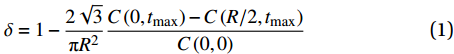
图 5 不同预制体孔径下WC/Fe复合材料复合层的元素分布Figure 5. Element distribution of layer in WC/Fe composites with different hole diameters of preform图6为不同预制体孔径下WC/Fe复合材料复合层原孔内的W质量分数分布。其原孔壁处W质量分数较高,而在其原孔心处较低。与晶粒尺寸的变化相反,随预制体孔径增加,其原孔壁处W质量分数基本不变,而在其原孔心处先增大后减小。为进一步表征W扩散均匀性,通过计算得不同预制体孔径下W扩散均匀性分别为84.1%、88.7%、86.9%,表明W扩散均匀性随其孔径增加而先增大后减小,W扩散均匀性的表达式为
![]() 图 6 不同预制体孔径下WC/Fe复合材料复合层原孔内的W质量分数分布Figure 6. W mass fraction distribution into initial hole of layer in WC/Fe composites with different hole diameters of preform
图 6 不同预制体孔径下WC/Fe复合材料复合层原孔内的W质量分数分布Figure 6. W mass fraction distribution into initial hole of layer in WC/Fe composites with different hole diameters of preformδ=1−2√3πR2C(0,tmax (1) 式中:δ为W扩散均匀性;C(0,tmax)、C(R/2,tmax)分别为预制体原孔壁、原孔心处W质量分数。
2.2 WC/Fe复合材料复合层的硬度分布与耐磨性
图7为不同预制体孔径下WC/Fe复合材料复合层原孔内的硬度分布。其原孔壁处硬度较高,而在其原孔心处较低。与W质量分数的变化相同,随预制体孔径增加,其原孔壁处硬度基本不变,而在其原孔心处先增大后减小。图8为不同预制体孔径下WC/Fe复合材料复合层原孔心处的磨损形貌。R=3 mm时其原孔心处犁沟最明显,R=9 mm时次之,R=6 mm时最不明显。图9为不同预制体孔径下WC/Fe复合材料复合层的磨损量。表明复合层耐磨性随其孔径增加而先增大后减小。
![]() 图 7 不同预制体孔径下WC/Fe复合材料复合层原孔内的硬度分布Figure 7. Hardness distribution into initial hole of layer in WC/Fe composites with different hole diameters of preform
图 7 不同预制体孔径下WC/Fe复合材料复合层原孔内的硬度分布Figure 7. Hardness distribution into initial hole of layer in WC/Fe composites with different hole diameters of preform![]() 图 8 不同预制体孔径下WC/Fe复合材料复合层原孔心处的磨损形貌Figure 8. Wear morphologies at initial hole center of layer in WC/Fe composites with different hole diameters of preform
图 8 不同预制体孔径下WC/Fe复合材料复合层原孔心处的磨损形貌Figure 8. Wear morphologies at initial hole center of layer in WC/Fe composites with different hole diameters of preform![]() 图 9 不同预制体孔径下WC/Fe复合材料复合层的磨损量Figure 9. Wear amount of layer in WC/Fe composites with different hole diameters of preform
图 9 不同预制体孔径下WC/Fe复合材料复合层的磨损量Figure 9. Wear amount of layer in WC/Fe composites with different hole diameters of preform2.3 WC/Fe复合材料复合层的W扩散均匀性机制
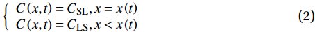
为进一步探究影响W扩散均匀性的因素,对预制体原孔内W质量分数分布进行数值模拟。将W扩散区看作受固液界面移动驱动的半无限大物体,且扩散时间近似为预制体孔内熔体凝固时间[21-22]。下式为W扩散区边界条件的表达式:
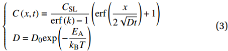
\left\{ \begin{array}{l} C\left( {x,t} \right) = {C_{{\rm{SL}}}},x = x\left( t \right) \\ C\left( {x,t} \right) = {C_{{\rm{LS}}}},x < x\left( t \right) \end{array}\right. (2) 式中,CSL、CLS分别为固液界面固、液相侧W质量分数。根据Arrhenius方程,W质量分数分布为
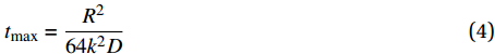
\left\{ \begin{array}{l} C\left( {x,t} \right) = \dfrac{{{C_{{\rm{SL}}}}}}{{{\rm{erf}}\left( k \right) - 1}}\left( {{\rm{erf}}\left( {\dfrac{x}{{2\sqrt {Dt} }}} \right) + 1} \right) \\ D = {D_0}{\rm{exp}}\left( { - \dfrac{{{E_{\rm{A}}}}}{{{k_{\rm{B}}}T}}} \right) \end{array} \right. (3) 式中:x为W扩散距离;t为W扩散时间;T为W扩散温度;D为W扩散系数;k为常数;EA为W元素扩散激活能;kB为玻尔兹曼常数[22]。W扩散总时间为
{t_{{\rm{max}}}} = \frac{{{R^2}}}{{64{k^2}D}} (4) 通过解析解得W扩散过程同时受温度与固液界面移动影响。故先采用有限元模拟软件COMSOL Multiphysics 5.4模拟预制体孔内熔体凝固时的温度场与相场,表4为预制体孔内熔体凝固时热物理场模拟的参数设置。图10为预制体孔内熔体凝固时热物理场的有限元模拟。发现固液界面明显存在,且其左侧温度较高,熔体为液相,而其右侧温度较低,熔体为固相,即其孔壁处熔体先凝固,且固液界面移动驱动W扩散。此外,随预制体孔径增加,其孔内熔体高温区增多,使其平均温度增高,W扩散系数受W扩散温度影响,扩散温度越高扩散系数越大,其原孔内W质量分数分布曲线斜率绝对值越大;图11为不同预制体孔径下WC/Fe复合材料复合层原孔内W质量分数分布的数值模拟。再将该有限元模拟结果代入数学分析软件MATLAB R2015b的二次开发程序中进行数值模拟,最终得其原孔内W质量分数分布曲线,发现其原孔内W质量分数为W扩散距离的单调递减函数。因预制体孔径孔距比相同且W扩散区为受固液界面移动驱动的半无限大物体,故设置W初始质量分数相同。随预制体孔径增加,其原孔内W质量分数分布曲线斜率绝对值增大,故R=3 mm时其原孔心处W质量分数较R=6 mm时低,但R=6 mm时W扩散距离较R=9 mm时短,故其原孔心处W质量分数R=6 mm时最高,R=9 mm时次之,R=3 mm时最低,即该数值模拟与实验结果相符。
表 4 预制体孔内熔体凝固时热物理场模拟的参数设置Table 4. Parameters setting of thermal physical field simulation when internal matrix of preform solidifiesPhase Density/(kg·m−3) Thermal conductivity/(W·m−1·K−1) Heat capacity/(J·kg−1·K−1) Fe(s) 8 500 200 400 Fe(l) 7 800 450 550 Inlet temperature/°C Melting temperature/°C Temperature transition half width/K Surface emissivity 1 500 1 100 50 0.8 Specific heat/(J·kg−1·K−1) Solidification latent heat/(kJ·kg−1) Heat transfer coefficient/(W·m−2·K−1) 60 200 800 ![]() 图 10 不同预制体孔径下孔内熔体凝固时热物理场的有限元模拟Figure 10. Finite element simulation of thermal physical field when internal matrix solidifies with different hole diameters of preform
图 10 不同预制体孔径下孔内熔体凝固时热物理场的有限元模拟Figure 10. Finite element simulation of thermal physical field when internal matrix solidifies with different hole diameters of preform![]() 图 11 不同预制体孔径下WC/Fe复合材料复合层原孔内W质量分数分布的数值模拟Figure 11. Numerical simulation of W mass fraction distribution in initial hole in WC/Fe composites with different hole diameters of preform
图 11 不同预制体孔径下WC/Fe复合材料复合层原孔内W质量分数分布的数值模拟Figure 11. Numerical simulation of W mass fraction distribution in initial hole in WC/Fe composites with different hole diameters of preform预制体孔径较大时,其孔内熔体较多,温度也较高。一方面扩散时间较长,有利于W扩散;另一方面扩散距离较长,不利于W扩散均匀,使预制体原孔心处W质量分数降低。同理,预制体孔径较小时,扩散距离虽短,但扩散时间较短,使W扩散不充分,其原孔心处W质量分数较低,故W扩散均匀性也较低;故预制体孔径适中时,因兼顾扩散距离与扩散时间而使W扩散均匀性最高。综上所述,W扩散过程同时受扩散距离与扩散时间的影响。
2.4 WC/Fe复合材料复合层的耐磨性与W扩散均匀性间关联机制
亚共晶Fe-Cr-C系合金中含大量低硬度、高韧性的一次奥氏体,硬度、耐磨性较低,而W弥散分布在一次奥氏体枝晶内形成M6C型碳化物Fe3W3C,细化晶粒使复合层冲击韧性未明显降低,且引入硬质相使其硬度明显提高[20,23],一定范围内也提高其耐磨性[24]。W扩散均匀性越高,预制体原孔心处W质量分数越高,形成硬质相越多,硬度也越高,最终提高复合层耐磨性。
3. 结 论
采用真空消失模铸渗(V-EPC)工艺制备WC/Fe复合材料,选取预制体孔径孔距比相同孔径不同的蜂窝预制体,并将其原孔壁与原孔心处W质量分数作为W扩散均匀性的判断条件,得如下结论。
(1) WC高温下分解,W由预制体孔壁至孔心处扩散,形成弥散分布的硬质相Fe3W3C。
(2)预制体原孔壁与原孔心处W质量分数与硬度相差随孔径增加而先增大后减小,复合层耐磨性的变化亦然。
(3) W扩散均匀性同时受扩散距离与扩散时间的影响。预制体孔径较小时,扩散距离虽短,但扩散时间较短,不利于W扩散;预制体孔径较大时,扩散时间虽长,但扩散距离增长,仍不利于W扩散;预制体孔径适中时,因兼顾扩散距离与扩散时间,利于W扩散。
(4)耐磨性与W扩散均匀性间存在关联,W扩散均匀性越高,预制体原孔心处W质量分数越高,形成硬质相越多,硬度也越高,一定范围内复合层耐磨性也越高。
-
![]()
图 2 复合鳞片与防弹插板图片
Figure 2. Pictures of composite scale and ballistic plate ((a) Composite scale; (b) Ballistic plate; (c) X-ray photograph of ballistic plate)
![]()
图 4 复合鳞片和垫层局部加密网格
Figure 4. Denser finite element mesh in partial areas of composite scale and backing layers
![]()
图 6 7.62 mm手枪弹侵彻后防弹插板X射线与局部破坏照片
Figure 6. X-ray photographs and local damage photos of ballistic plate after the penetration of 7.62 mm handgun bullet( (a) Lead-core bullet; (b) Steel-core bullet)
![]()
图 7 图6中侵彻点(4)处防弹插板破坏形貌
Figure 7. Appearance of ballistic plate at reference point (4) in Fig.6 ((a) Composite scale; (b) Backing layers)
![]()
图 8 7.62 mm手枪弹破坏形貌
Figure 8. Failure morphologies of 7.62 mm handgun bullets ( (a) Lead-core bullet; (b) Steel-core bullet)
![]()
图 9 试验测试和数值模拟的防弹插板凹陷深度对比
Figure 9. Comparison of back-face signature of ballistic plate obtained by experiments and finite element simulations
![]()
图 10 7.62 mm铅芯手枪弹侵彻防弹插板的破坏过程
Figure 10. Damage process of ballistic plate penetrated by 7.62 mm lead-core handgun bullet
![]()
图 11 7.62 mm铅芯手枪弹z方向速度和加速度-时间曲线
Figure 11. Velocity and acceleration-time history curves in z direction of 7.62 mm lead-core handgun bullet
![]()
图 12 7.62 mm铅芯手枪弹侵彻防弹插板的Von Mises应力云图
Figure 12. Von Mises stress contours of ballistic plate under the penetration of 7.62 mm lead-core handgun bullet ( (a) SiC layer of composite scale; (b) UHMWPE layer of composite scale; (c) Backing layers)
![]()
图 13 集中荷载作用下防弹插板的荷载-位移曲线
Figure 13. Load-displacement curves of ballistic plate under concentrated loading
表 1 SiC陶瓷的物理力学性能
Table 1 Physical and mechanical properties of SiC ceramic
Density/
(g·cm−3)Elastic modulus/
GPaVickers hardness/
HVCompressive strength/
MPaFlexural strength/
MPaFracture toughness/
(MPa·m1/2)3.10 410 2 600 2 200 400 4.0  下载: 导出CSV
表 2 超高分子量聚乙烯(UHMWPE)纤维与Kevlar纤维的物理力学性能
Table 2 Physical and mechanical properties of ultrahigh molecular weight polyethylene (UHMWPE) fiber and Kevlar fiber
Type of fiber Density/(g·cm−3) Tensile strength/MPa Tensile modulus/GPa Elongation at break/% UHMWPE 0.97 3.0 95 3.6 Kevlar 1.44 3.38 83 3.3
下载: 导出CSV
ρ/(g·cm−3) G/GPa A B C M N 3.10 183 0.96 0.35 0.0 1.0 0.65 Reference strain rate Tensile strength/GPa Normalized fracture strength Hugoniot elastic limit (HEL)/GPa HEL pressure/GPa HEL Vol. strain HEL strength/GPa 1.0 0.37 0.8 14.567 5.9 0 13.0 D1 D2 K1/GPa K2/GPa K3/GPa β PSFAIL 0.48 0.48 204.785 0 0 1.0 - Notes: ρ—Density; G—Shear modulus; A—Intact normalized strength parameter; B—Fractured normalized strength parameter; C—Strength parameter (for strain rate dependence) ; M—Fractured strength parameter (pressure exponent) ; N—Intact strength parameter (pressure exponent) ; D1—Parameter for plastic strain to fracture; D2—Parameter for plastic strain to fracture (exponent) ; K1—First pressure coefficient (equivalent to the bulk modulus) ; K2—Second pressure coefficient; K3—Elastic constants; β—Fraction of elastic energy loss converted to hydrostatic energy; PSFAIL—Effective plastic strain at failure.
下载: 导出CSV
ρ/(g·cm−3) P1 P2 P3 P4 P5 P6 0.97 5.796 5.796 6.12561 0.025 3.58889 0.41368 P7 P8 P9 P10 P11 P12 P13 0.25 3.709 2.884 1 0.05 6.6939 0.05 P14 P15 P16 P17 P18 P19 P20 2.29 2.29 0.025 0.2645 0 0.185 1.3328 P21 P22 P23 P24 P25 P26 P27 0.28285 4.63 0.28285 4.63 0.28285 2.25 −0.005 Notes: P1, P2, P3—Moduli of elasticity in x, y and z directions; P4—Stretching poisson's ratio in xy plane; P5—Shear modulus in xy plane; P6—Yield stress in xy plane; P7—Failure strain in xy direction; P8, P9—Linear buckling parameters; P10—Unloading modulus factor in xy plane; P11—xy plane; P12—Unloading modulus in z direction; P13—Tensile modulus factor in z directions; P14, P15, P16—Shear moduli in yz, zx and xy planes; P17—Compression failure strain in z directions; P18—Tensile failure strain in z direction; P19—Local strain of area 1 in z direction; P20—Modulus of elasticity of area 1 in z direction; P21, P22—C, P parameters of area 2; P23, P24—C, P parameters of area 1; P25, P26—C, P parameters in xy plane; P27—Parameter of strain rate.
下载: 导出CSV
Material Density/(g·cm−3) Modulus of elasticity/GPa Poisson's ratio Yield stress/GPa Tangent modulus/GPa Lead 11.270 17 0.40 0.008 0.015 Steel 7.850 210 0.33 0.355 0.0 Copper 8.858 117 0.40 0.345 0.0
下载: 导出CSV
表 6 防弹插板弹道性能测试结果
Table 6 Test result of ballistic performance of ballistic plate
Bullet material Number of reference point Muzzle velocity/(m·s−1) Backface signature/mm Number of penetrated backing layers Lead-core bullet (1) 442 7.2 0 (2) 437 9.0 3 (3) 445 10.5 4 Steel-core bullet (4) 433 8.1 6 (5) 435 10.2 8 (6) 432 13.5 17
下载: 导出CSV
-
[1] LIU W, CHEN Z, CHENG X, et al. Design and ballistic penetration of the ceramic composite armor[J]. Composites Part B: Engineering,2016,84:33-40. DOI: 10.1016/j.compositesb.2015.08.071
[2] SARVA S, NEMAT-NASSER S, MCGEE J, et al. The effect of thin membrane restraint on the ballistic performance of armor grade ceramic tiles[J]. International Journal of Impact Engineering,2007,34(2):277-302. DOI: 10.1016/j.ijimpeng.2005.07.006
[3] MEDVEDOVSKI E. Ballistic performance of armour ceramics: Influence of design and structure. Part 1[J]. Ceramics International,2010,36(7):2103-2115. DOI: 10.1016/j.ceramint.2010.05.021
[4] TABIEI A, NILAKANTAN G. Multi-scale ballistic impact simulation of dry woven fabric with elastic crimped fibers[J]. International Journal of Vehicle Structures & Systems (IJVSS),2011,3(2):74-79.
[5] NAIK N K, KUMAR S, RATNAVEER D, et al. An energy-based model for ballistic impact analysis of ceramic-composite armors[J]. International Journal of Damage Mechanics,2013,22(2):145-187. DOI: 10.1177/1056789511435346
[6] LIU W, CHEN Z, CHEN Z, et al. Influence of different back laminate layers on ballistic performance of ceramic composite armor[J]. Materials & Design,2015,87:421-427.
[7] EVCI C, Gülgeç M. Effective damage mechanisms and performance evaluation of ceramic composite armors subjected to impact loading[J]. Journal of Composite Materials,2014,48(26):3215-3236. DOI: 10.1177/0021998313508594
[8] JIUSTI J, KAMMER E H, NECKEL L, et al. Ballistic performance of Al2O3 mosaic armors with gap-filling materials[J]. Ceramics International,2017,43(2):2697-2704. DOI: 10.1016/j.ceramint.2016.11.087
[9] HUANG G W, CHEN A J, LUO S M, et al. Study on numerical simulation of projectile penetrating UHMWPE fiber layers and effects of projectile parameters[C]//Advanced Materials Research. Trans Tech Publications, 2013, 630: 121-126.
[10] ZHANG T G, SATAPATHY S S, VARGAS-GONZALEZ L R, et al. Ballistic impact response of ultra-high-molecular-weight polyethylene (UHMWPE)[J]. Composite Structures,2015,133:191-201. DOI: 10.1016/j.compstruct.2015.06.081
[11] HU D, ZHANG Y, SHEN Z, et al. Investigation on the ballistic behavior of mosaic SiC/UHMWPE composite armor systems[J]. Ceramics International,2017,43(13):10368-10376. DOI: 10.1016/j.ceramint.2017.05.071
[12] 朱德举, 张超慧, 刘鹏. 天然和仿生柔性生物结构的设计[J]. 复合材料学报, 2018, 35(6):1636-1645. ZHU Deju, ZHANG Chaohui, LIU Peng. Study on the design of natural and biomimetic flexible biological structures[J]. Acta Materiae Compositae Sinica,2018,35(6):1636-1645(in Chinese).
[13] 朱德举, 赵波. 仿生柔性防护装具的设计及防弹性能测试[J]. 复合材料学报, 2020, 37(6):1411-1417. ZHU Deju, ZHAO Bo. Design and ballistic performance testing of bio-inspired flexible protection devices[J]. Acta Materiae Compositae Sinica,2020,37(6):1411-1417(in Chinese).
[14] LIU P, ZHU D, YAO Y, et al. Numerical simulation of ballistic impact behavior of bio-inspired scale-like protection system[J]. Materials & Design,2016,99:201-210.
[15] CHEN I H, KIANG J H, CORREA V, et al. Armadillo armor: Mechanical testing and micro-structural evaluation[J]. Journal of the Mechanical Behavior of Biomedical Materials,2011,4(5):713-722. DOI: 10.1016/j.jmbbm.2010.12.013
[16] KAUFMANN C, CRONIN D, WORSWICK M, et al. Influence of material properties on the ballistic performance of ceramics for personal body armour[J]. Shock and Vibration,2003,10(1):51-58. DOI: 10.1155/2003/357637
[17] BAIN A D. Non-scalar flexible rifle defeating armor system: US, 9, 534, 872[P]. 2017-1-3.
[18] 刘鹏. 鳞片多级结构、力学性能及其仿生研究[D]. 长沙: 湖南大学, 2017. LIU Peng. The research on hierarchical structure mechanical behavior and biomimetic of fish scales[D]. Changsha: Hu'nan University, 2017(in Chinese).
[19] 中国人民解放军总后勤部. 军用防弹衣安全技术性能要求: GJB 4300A—2012[S]. 北京: 中国标准出版社, 2012. The General Logistics Department of PLA. Requirements of safety technical performance for military body armor: GJB 4300A—2012[S]. Beijing: Standars Press of China, 2012(in Chinese).
[20] TEPEDUZU B, KARAKUZU R. Ballistic performance of ceramic/composite structures[J]. Ceramics International,2019,45(2):1651-1660. DOI: 10.1016/j.ceramint.2018.10.042
[21] BÜRGER D, DE FARIA A R, DE ALMEIDA S F M, et al. Ballistic impact simulation of an armour-piercing projectile on hybrid ceramic/fiber reinforced composite armours[J]. International Journal of Impact Engineering,2012,43:63-77. DOI: 10.1016/j.ijimpeng.2011.12.001
[22] CRONIN D S, BUI K, KAUFMANN C, et al. Implementation and validation of the Johnson-Holmquist ceramic material model in LS-Dyna[C]//Proceedings of the 4th European LS-DYNA Users Conference. 2003, 1: 47-60.
[23] DHANDAPANI K. Experimental investigation and development of a constitutive model for ultra high molecular weight polyethylene materials[D]. Phoenix: Arizona State University, 2009.
[24] 孙非, 马力, 朱一辉, 等. 手枪弹对带UHMWPE软防护明胶靶标冲击效应的数值分析[J]. 振动与冲击, 2018, 37(13):20-26. SUN Fei, MA Li, ZHU Yihui, et al. Numerical analysis for impact effects of a pistol bullet on a gelatin target covered with UHMWPE fiber armor[J]. Journal of Vibration and Shock,2018,37(13):20-26(in Chinese).
[25] CHELLURU S K. Finite element simulations of ballistic impact on metal and composite plates[D]. Wichita: Wichita State University, 2007.
-
期刊类型引用(0)
其他类型引用(1)
-


计量
- 文章访问数: 1978
- HTML全文浏览量: 619
- PDF下载量: 160
- 被引次数: 1
