


Load-bearing mechanism and full-process response characterization of a GFRP square tube bonded-bolted sleeve connection
-
摘要: FRP构件的接头部分是结构的潜在薄弱环节,在结构尺度计算中准确反映接头的全过程行为是FRP组合结构的设计难点。本文以压缩工况下拼装式GFRP格构柱为结构背景,以拉挤GFRP方管型材的胶栓混合套管连接接头为研究对象,设计制备了四个胶栓混合连接试件和两个纯螺栓连接试件,开展了轴压静载试验,并建立了考虑胶层失效行为的实体有限元模型。结果表明:该连接形式具有二次承载特性,其整体力学行为源于胶层剪切传力机制和螺栓剪切传力机制的叠加结果;对于本文试件,二次极值荷载达到了首次极值荷载的92%,挤压破坏荷载相较于纯螺栓连接试件平均提升了49%。针对胶栓混合套管连接,提出了一种简化建模方法,并基于连续损伤模型和塑性势理论建立了以力和位移表述的宏观本构,提炼出了具有明确物理意义的本构参数,可在结构尺度计算中以较小的计算成本准确考虑接头的全过程行为。宏观本构模型的唯象属性使得简化建模方法对于接头的力学行为描述较为准确,计算成本较小,能够适用于压缩工况下拼装式GFRP格构柱的结构尺度计算分析。Abstract: The connection region of FRP components is a potential weak link in structures. Accurately reflecting the full-process behavior of the joint in structural scale calculations is a challenging aspect in the design of FRP composite structures. In this study, assembled GFRP lattice columns subject to compression loads were used as the structural background, and the focus was on the research of bonded-bolted sleeve connections for pultruded GFRP square tubes. Four hybrid joint specimens and two pure bolted joint specimens were designed and prepared. Axial compression static load tests were conducted, and a solid FE model considering the failure behavior of the adhesive layer was established. The results indicate that the connection form exhibits a secondary load-carrying characteristic, and the overall mechanical behavior is derived from the superposition of the adhesive shear and bolt shear load transmitting mechanisms; regarding specimens in this paper, the secondary peak load reaches 92% of the first, and the bearing failure load is on average increased by 49% compared to pure bolted connection specimens. For the bonded-bolted sleeve connection, a simplified modeling approach is proposed. Based on the continuous damage model and the plastic potential theory, a macroscopic constitutive model in terms of force and displacement is established. This model distills constitutive parameters with clear physical meanings, enabling an accurate consideration of the full-process behavior of the joint in structural-scale calculations at a relatively low computational cost. The phenomenological nature of the macroscopic constitutive model leads to a relatively accurate description of the mechanical behavior of the joint, and the computational cost is small, making it suitable for structural scale calculation analysis of assembled GFRP latticed columns subject to compression loads.
-
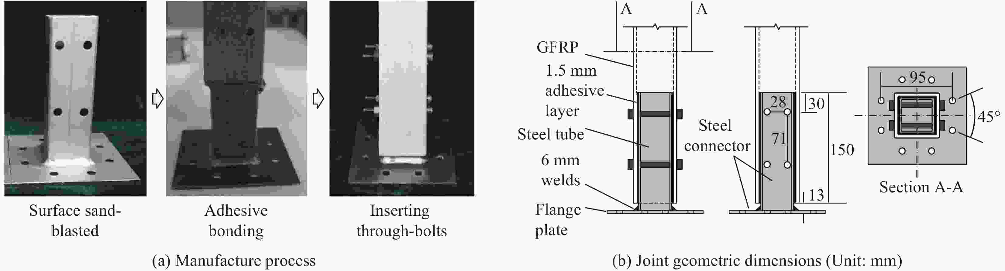
图 2 接头试件制备及几何尺寸
Figure 2. Manufacture process and geometric dimensions of the joint specimens

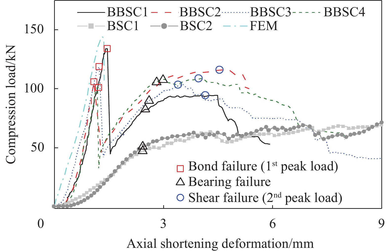
图 5 胶栓混合套管连接试件(BBSC)及螺栓套管连接试件(BSC)荷载-轴向缩短变形曲线
Figure 5. Load-axial shortening curves for the bonded-bolted sleeve connection (BBSC) and bolted sleeve connection (BSC) specimens

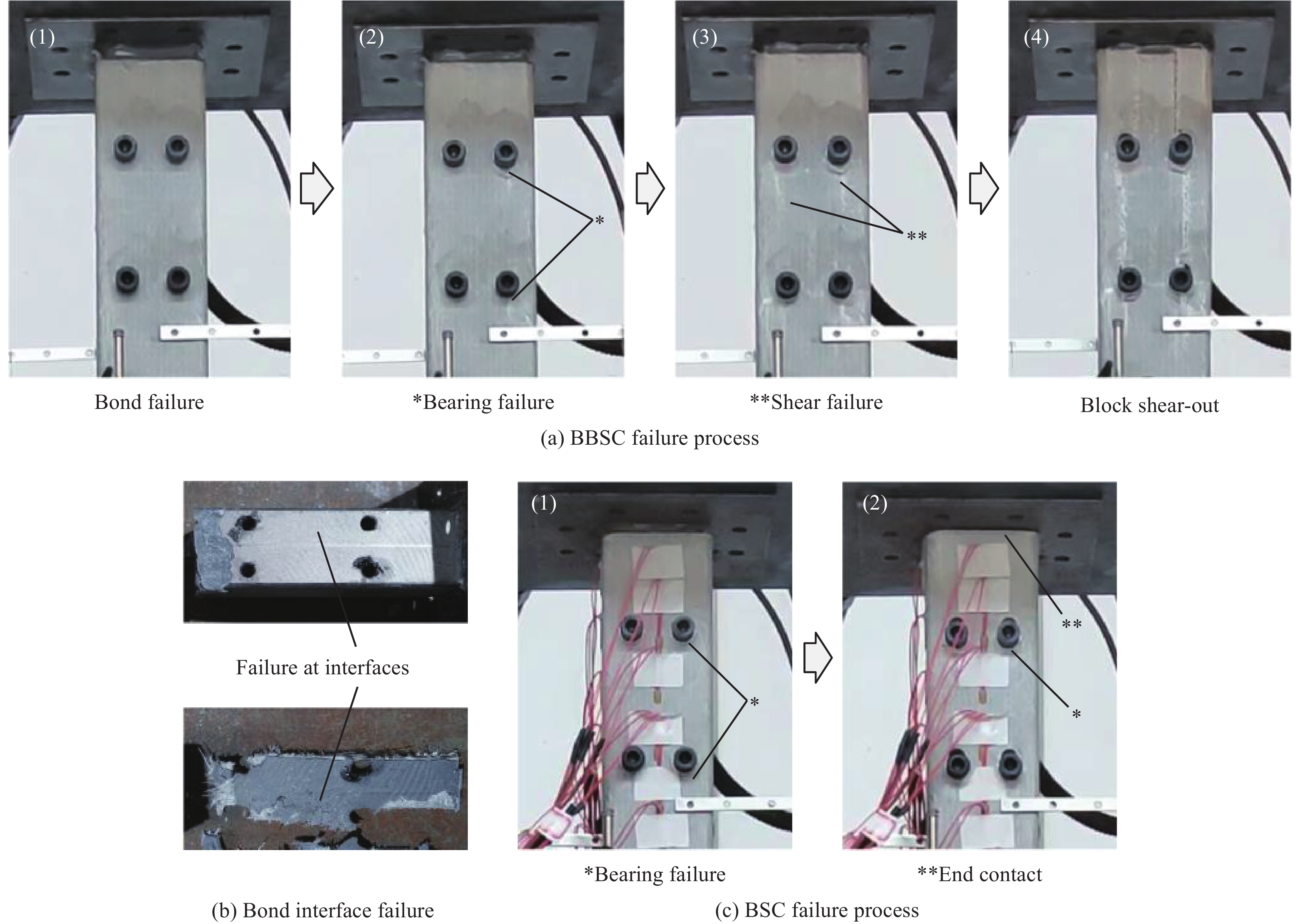
图 6 胶栓混合套管连接和螺栓套管连接试件失效过程
Figure 6. Failure processes of the bonded-bolted sleeve connection and bolted sleeve connection specimens
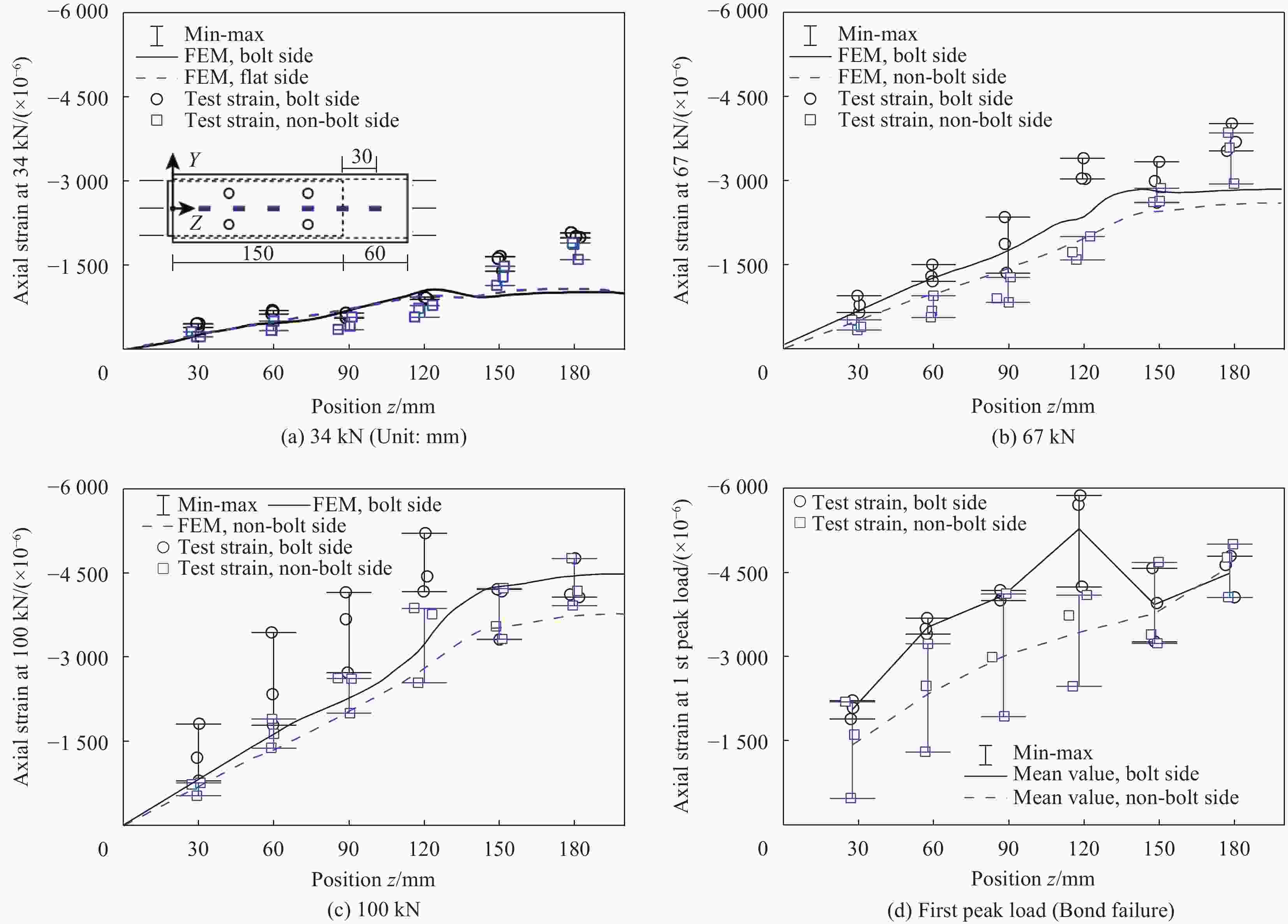
图 7 不同荷载水平下胶栓混合套管连接试件应变响应
Figure 7. Strain responses of the bonded-bolted sleeve connection specimens at different load levels

图 8 不同荷载水平下螺栓套管连接试件应变响应
Figure 8. Strain responses of the bolted sleeve connection specimens at different load levels
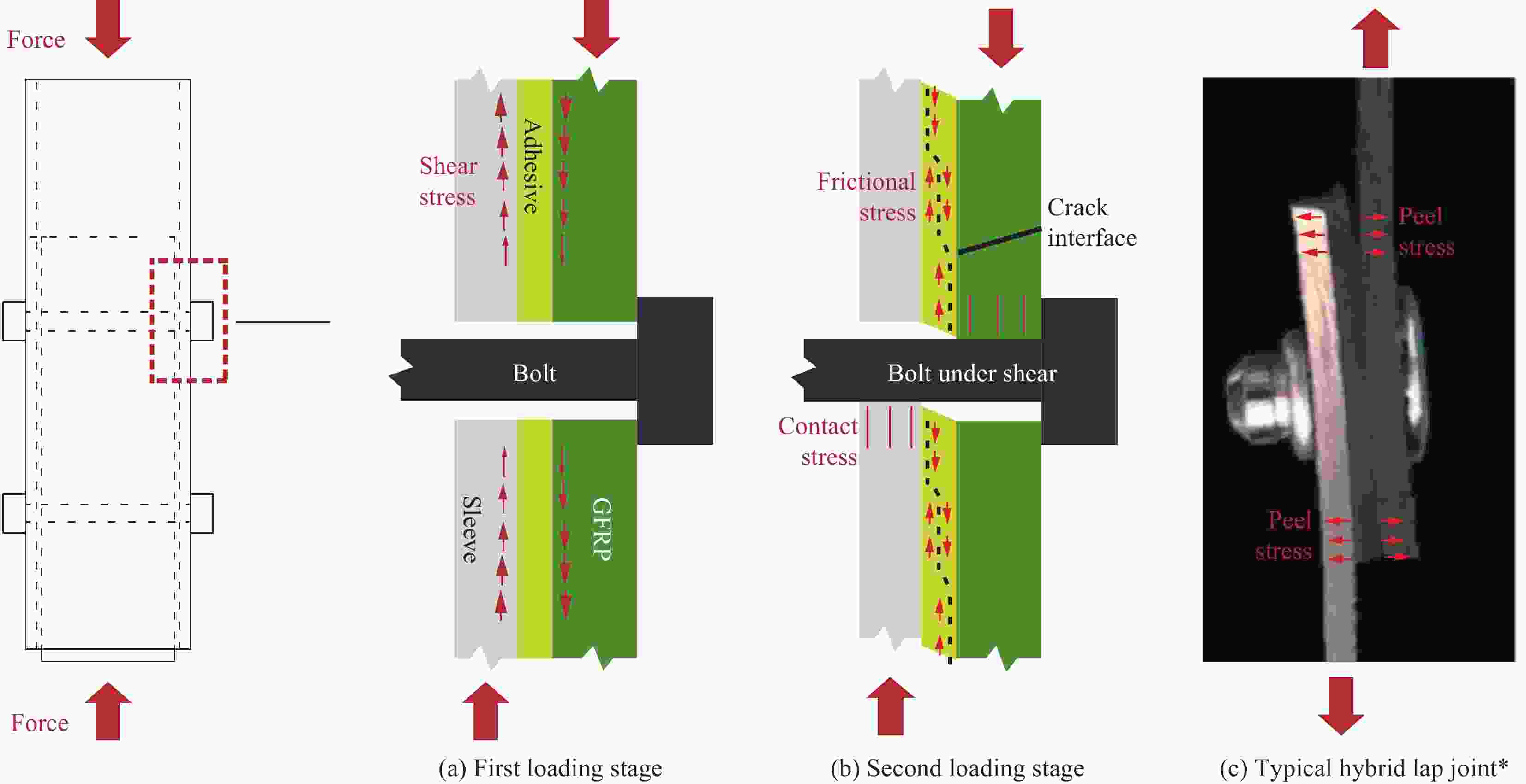
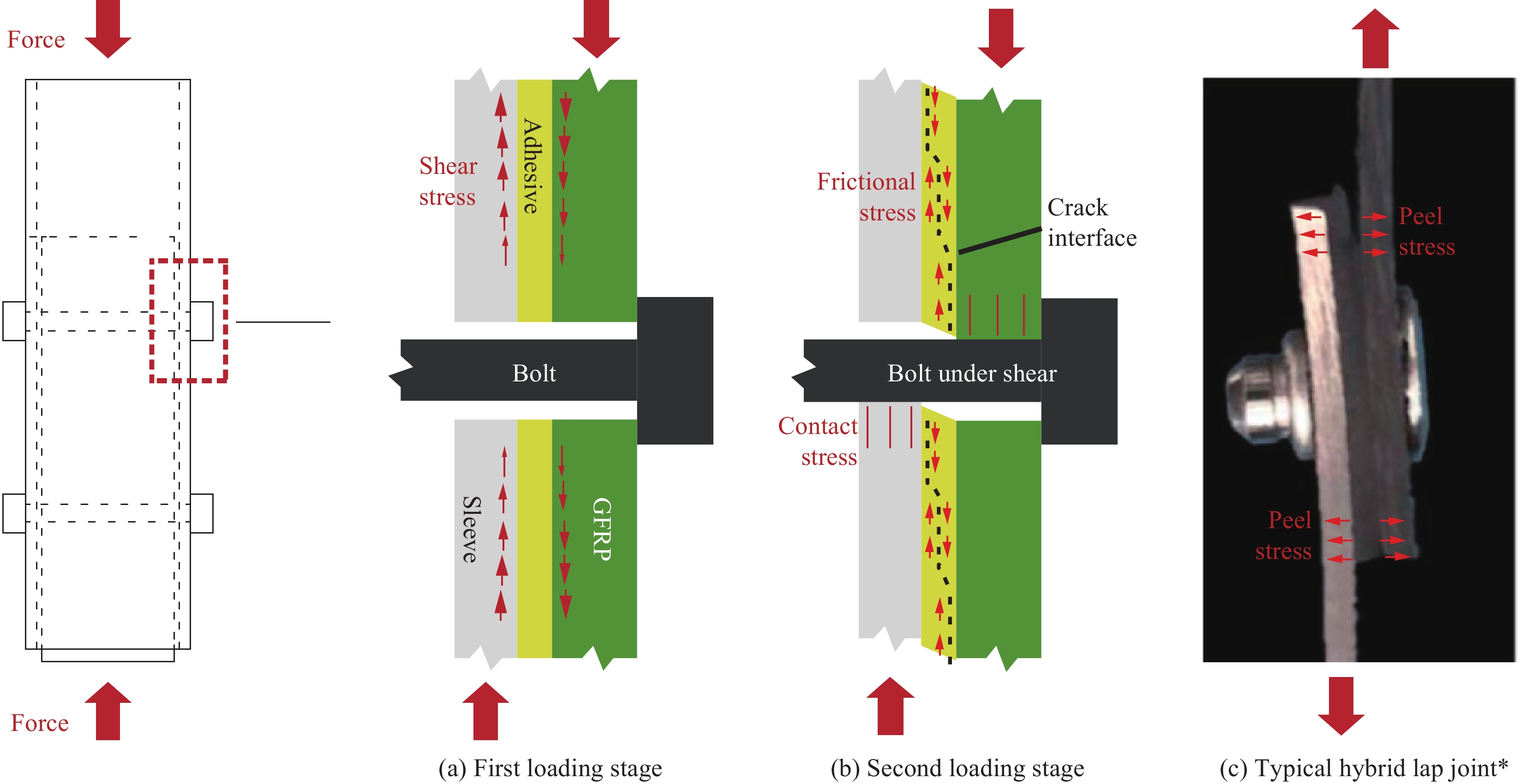
图 9 胶栓混合连接传力机制示意图
Figure 9. Schematic diagram for the load transmitting mechanism of bonded-bolted connections
*—Original photo without annotations is taken from reference [31]
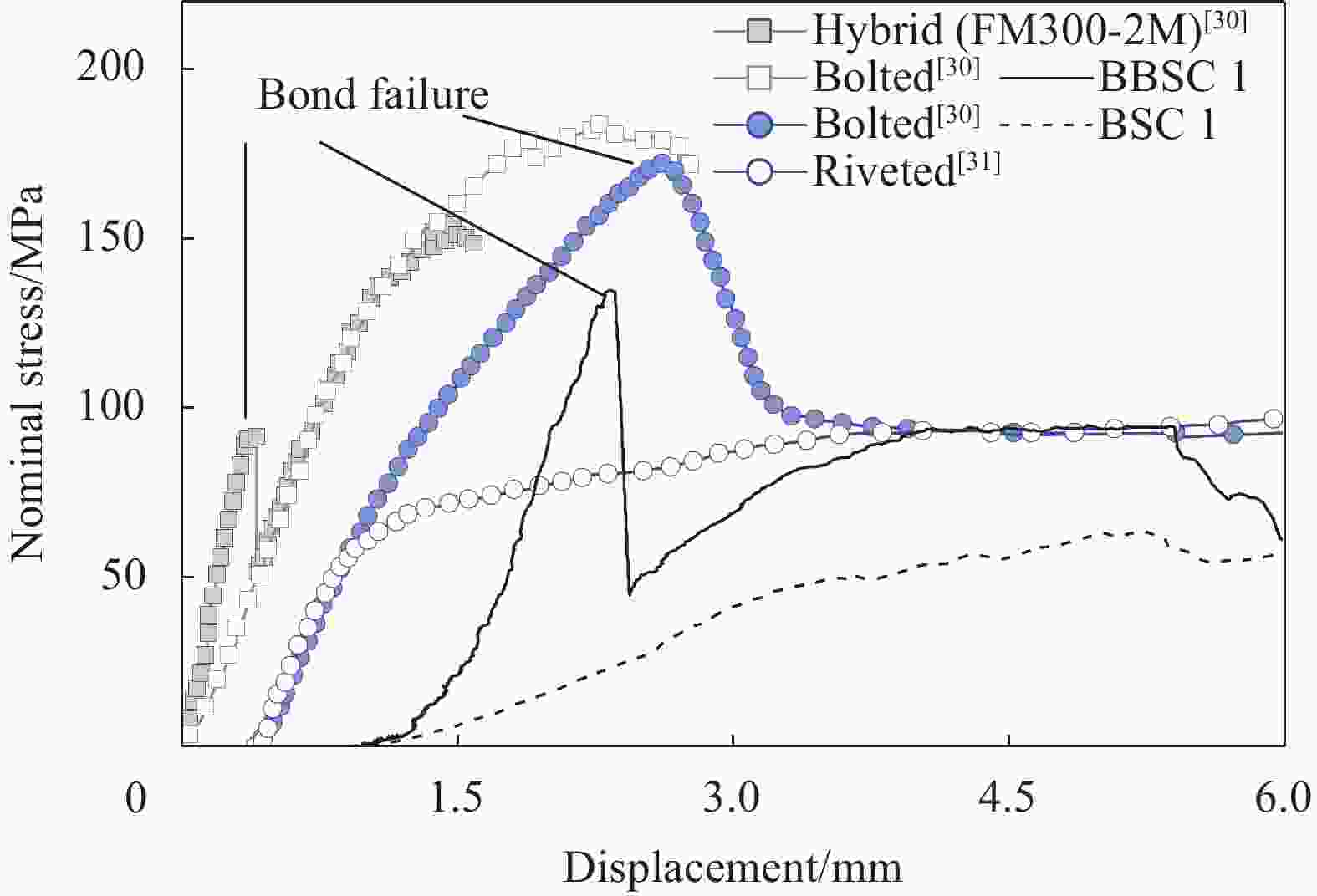
图 10 不同传力机制下接头的名义应力-位移曲线对比
Figure 10. Comparing the nominal stress-displacement relationship curves of joints with different load transmitting mechanisms
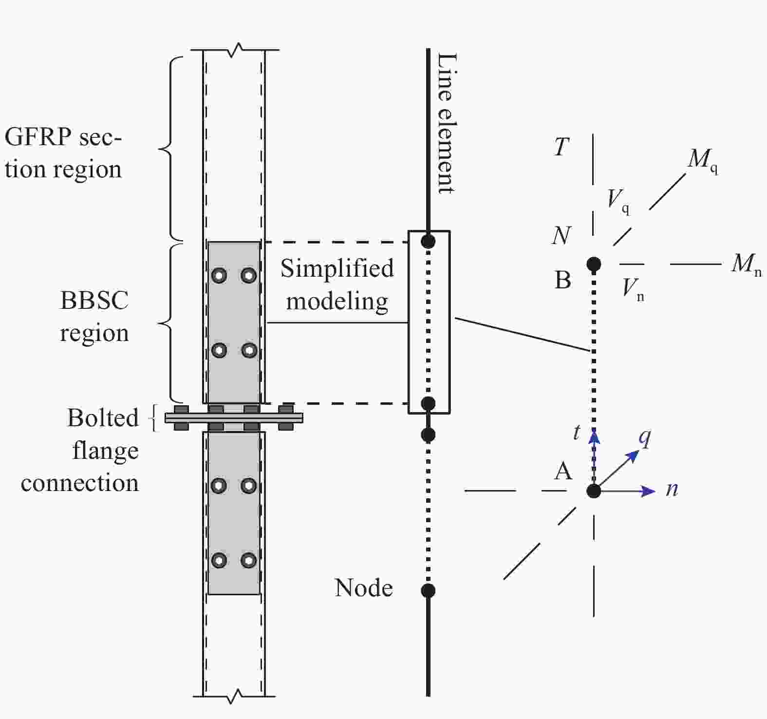
图 11 采用线单元构造弦杆接头简化模型
Figure 11. Developing simplified model for the joints of chords using line elements
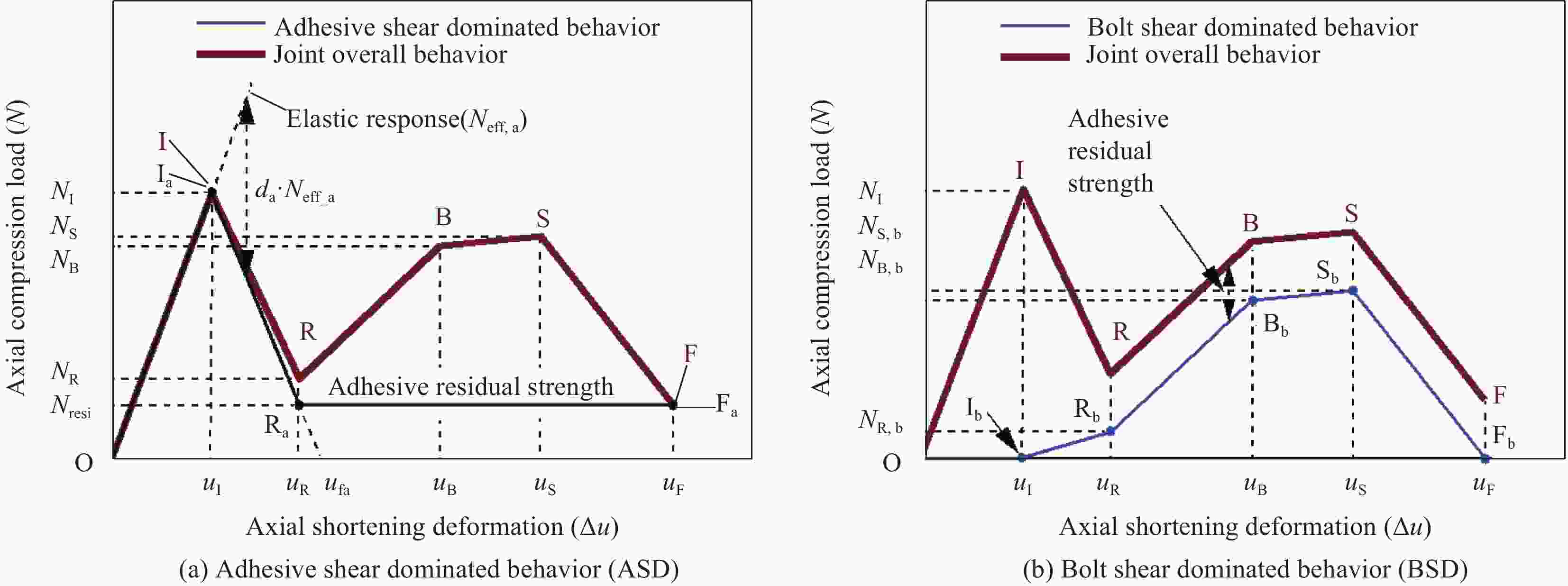
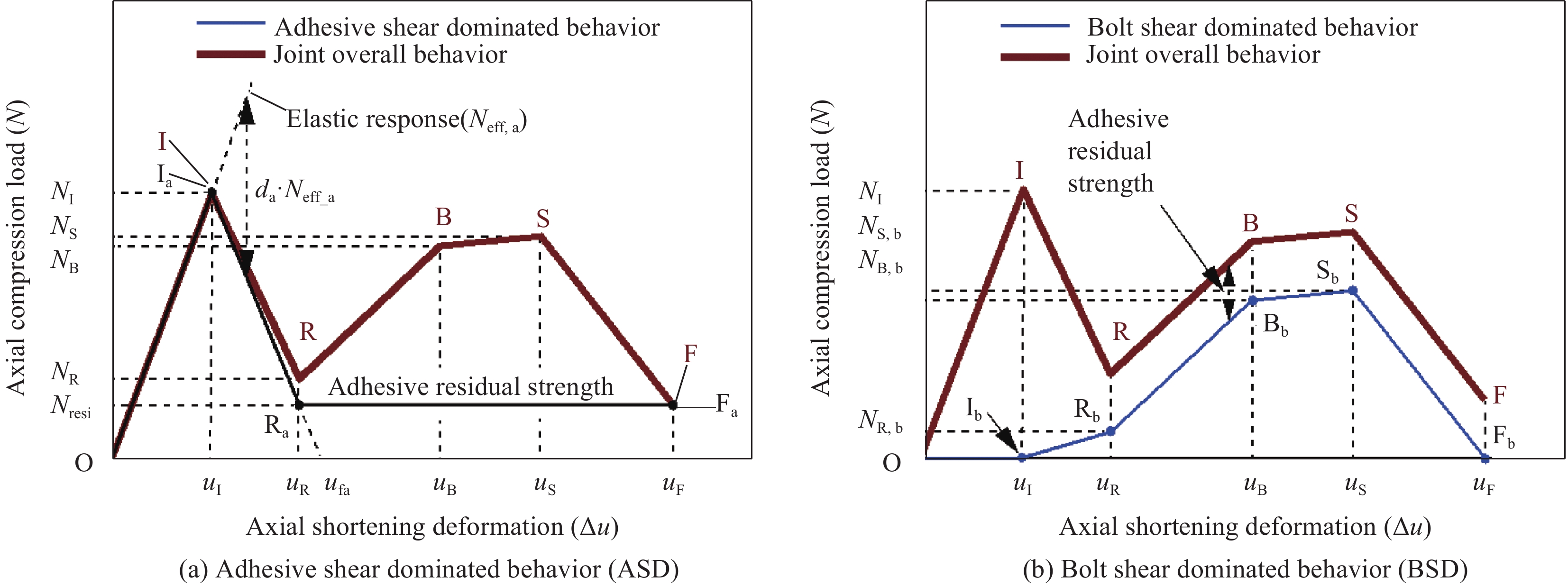
图 12 两种受力机制的本构关系曲线示意图
Figure 12. Schematic diagram of the constitutional relationship curves of the two load transmitting mechanisms
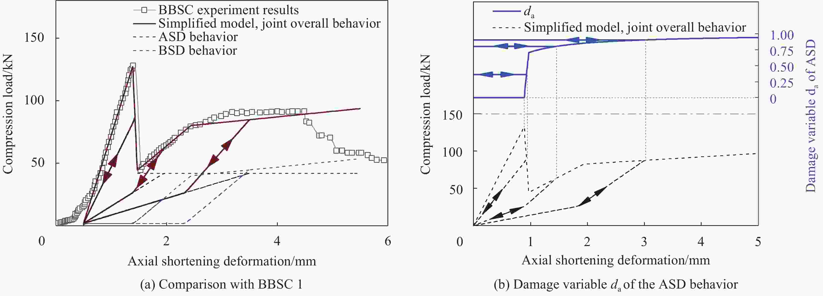
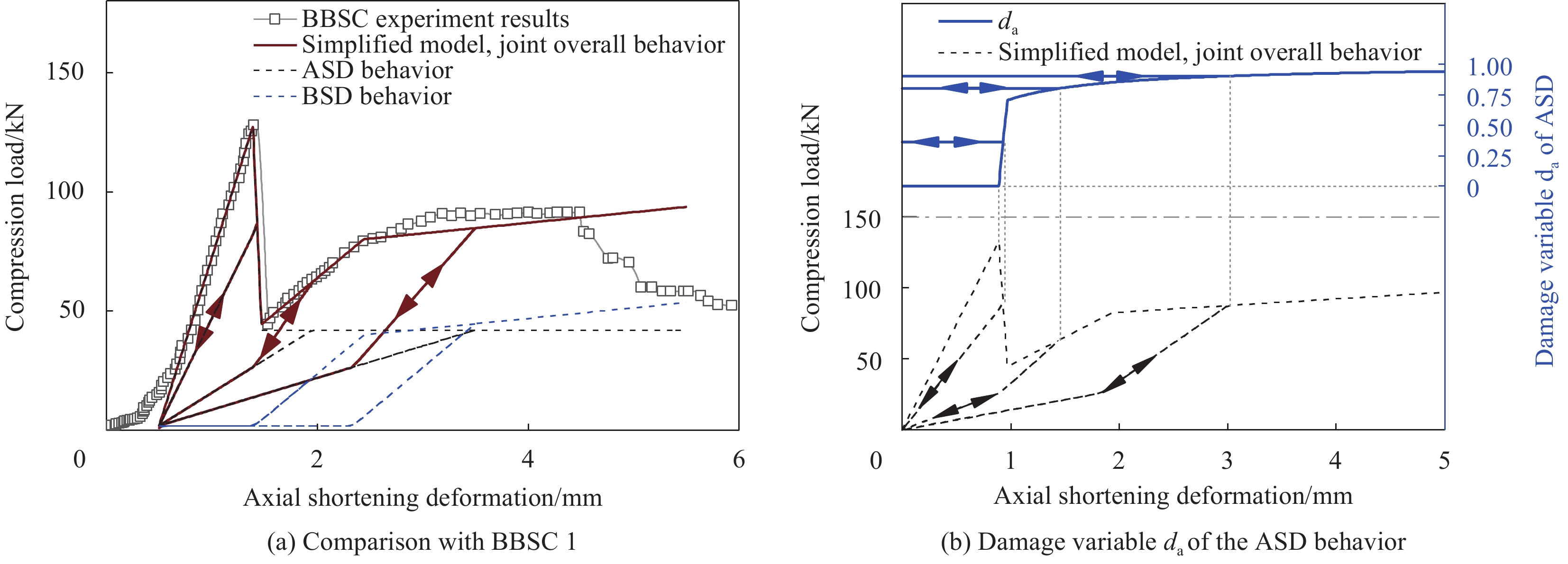
图 13 BBSC1简化建模方法荷载-位移曲线与试验结果对比
Figure 13. Comparison of the load-displacement curves of BBSC1 obtained through the simplified modeling method and experiments

表 1 材料参数
Table 1. Material properties
Component Modulus/GPa Strength (Yield strength)/MPa Poisson’s ratio Pultruded GFRP Longitudinal 29.7 429-456 0.3 Transverse 7.55 64.91 In-plane shear 3.0 27 Transverse shear 3.0 33.54 Steel flange and sleeve 210.0 345.0 0.3 M8 through-bolts 235.0* 1043* 0.42* Sikadur-330 CN Tensile 3.5 41.2 0.28 Shear 1.37 26.6 Note: *Data taken from Qiu 2019 [20].  下载: 导出CSV
表 2 BBSC和BSC试件试验结果汇总
Table 2. Summary of the experiment results of BBSC and BSC specimens
Specimen label Aa/mm2 ${N_{{\text{i,exp}}}}$/kN $\overline {{N_{{\text{i,exp}}}}} $/kN ${N_{{\text{i,FEM}}}}$/kN ${N_{{\text{B,exp}}}}$/kN $\overline {{N_{{\text{B,exp}}}}} $/kN ${N_{{\text{S,exp}}}}$/kN $\overline {{N_{{\text{S,exp}}}}} $/kN $\overline {{K_{{\text{a,exp}}}}} $/
(kN·mm−1)${K_{{\text{a,FEM}}}}$/
(kN·mm−1)BBSC1 4×48×
150132.6 114.6 144.1 82.5 96.4 94.4 105.7 142.63 117.7 BBSC2 105.9 107.5 116.1 BBSC3 118.8 90.0 103.4 BBSC4 101.2 105.5 108.8 BSC1 0 — — — 51.1 49.2 — — 30.7 — BSC2 — 47.3 — Notes: BBSC for Bonded-Bolted Sleeve Connection; BSC for Bolted Sleeve Connection; Subscript exp and FEM denote experiment value and 3 D FEM value, respectively; Variables with an overline $\overline {{N_{\text{x}}}} $ means average value of Nx; Aa-Adhesive bond area; ${N_{\text{i}}}$-Load at bond failure;${N_{\text{B}}}$-Load at bearing failure; ${N_{\text{S}}}$-Load at shear failure;${K_{\text{a}}}$- Axial compression stiffness of the joint.
下载: 导出CSV
表 4 BBSC1简化模型宏观本构参数
Table 4. Macroscopic constitutive parameters for the simplified model of BBSC1
Adhesive shear dominated behavior Bolt shear dominated behavior NI 132.60 kN NR 44.77 kN uI 0.89 mm NB 82.50 kN uR 0.97 mm uB 1.94 mm Nresi 42.31 kN NS 94.40 kN uS 3.59 mm
下载: 导出CSV
表 3 BBSC1荷载-位移曲线关键位置数据
Table 3. Key position data of the BBSC1’s load-displacement curve
First loading stage Second loading stage NI,exp 132.60 kN NR,exp 44.77 kN uI,exp 1.45 mm uR,exp 1.53 mm $ K_{{\text{a,exp}}}^{{\text{BBSC}}} $ 149.1 kN/mm NB,exp 82.50 kN $ K_{{\text{a,exp}}}^{{\text{BSC}}} $ 30.7 kN/mm uB,exp 2.50 mm NS,exp 94.40 kN uS,exp 4.15 mm Notes: (uI,exp, NI,exp), (uB,exp, NB,exp), and (uS,exp, NS,exp) correspond to the Bond failure, Bearing failure, and Shear failure points in Fig. 5, respectively; (uR,exp, NR,exp) corresponds to the start point of the second loading stage;$ K_{{\text{a,exp}}}^{{\text{BBSC}}} $ and $ K_{{\text{a,exp}}}^{{\text{BSC}}} $ are the compression stiffness of the BBSC and BSC joint, respectively.
下载: 导出CSV
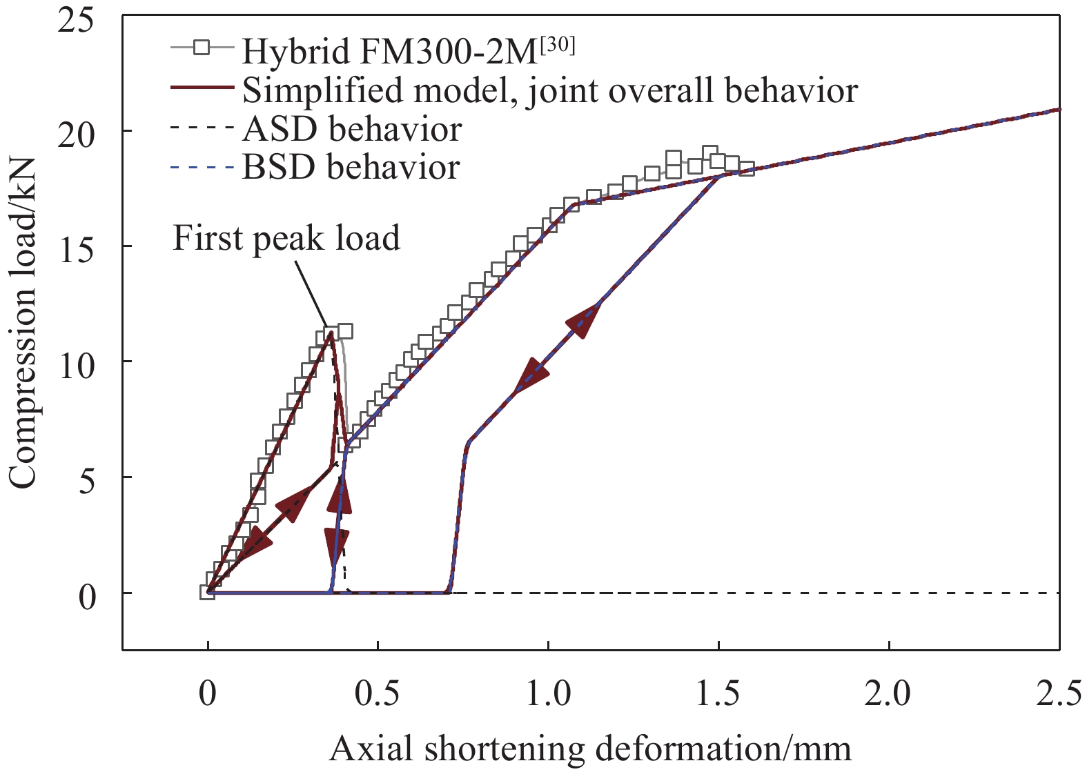
表 5 文献[30]中胶栓混合搭接接头简化模型宏观本构参数
Table 5. Macroscopic constitutive parameters for the simplified model of the bonded-bolted lap joint from the reference [30]
Adhesive shear dominated behavior Bolt shear dominated behavior NI 11.29 kN NR 6.37 kN uI 0.3636 mm NB 16.78 kN uR 0.4064 mm uB 1.0695 mm Nresi 0 kN NS 19.01 kN uS 1.4759 mm
下载: 导出CSV
-
[1] YANG X, BAI Y, DING F. Structural performance of a large-scale space frame assembled using pultruded GFRP composites[J]. Composite Structures, 2015, 133: 986-96. doi: 10.1016/j.compstruct.2015.07.120 [2] ZHU R, LI F, SHAO F, et al. Static and dynamic behaviour of a hybrid PFRP-aluminium space truss girder: Experimental and numerical study[J]. Composite Structures, 2020, 243: 112226. doi: 10.1016/j.compstruct.2020.112226 [3] LUO F J, HUANG Y, HE X, et al. Development of latticed structures with bolted steel sleeve and plate connection and hollow section GFRP members[J]. Thin-Walled Structures, 2019, 137: 106-16. doi: 10.1016/j.tws.2018.12.036 [4] BOSCATO G, CASALEGNO C, RUSSO S, et al. Buckling of Built-Up Columns of Pultruded Fiber-Reinforced Polymer C-Sections[J]. Journal of Composites for Construction, 2014, 18(4): 04013050. doi: 10.1061/(ASCE)CC.1943-5614.0000453 [5] 陈勇, 许金一, 谢芳, 等. GFRP输电塔T形节点抗弯承载力[J]. 复合材料学报, 2023, 41: 1-14.CHEN Y, XU J, XIE F, et al. Flexural bearing capacity of T-shaped joints in GFRP transmission towers[J]. Acta Materiae Compositae Sinica, 2023, 41: 1-14(in Chinese). [6] 詹瑒. 纤维增强复合材料(FRP)格构柱基本性能研究 [D]. 南京; 东南大学, 2016.ZHAN Y. Performance evaluation of lattice columns using pultruded fiber-reinforced polymer (FRP) structural profiles [D]. Nanjing: Southeast University, 2016(in Chinese). [7] XIE L, BAI Y, QI Y, et al. Pultruded GFRP square hollow columns with bolted sleeve joints under eccentric compression[J]. Composites Part B:Engineering, 2019, 162: 274-82. doi: 10.1016/j.compositesb.2018.11.001 [8] LUO F J, BAI Y, YANG X, et al. Bolted Sleeve Joints for Connecting Pultruded FRP Tubular Components[J]. Journal of Composites for Construction, 2016, 20(1): 04015024. doi: 10.1061/(ASCE)CC.1943-5614.0000580 [9] LUO F J, YANG X, BAI Y. Member Capacity of Pultruded GFRP Tubular Profile with Bolted Sleeve Joints for Assembly of Latticed Structures[J]. Journal of Composites for Construction, 2016, 20(3): 04015080. doi: 10.1061/(ASCE)CC.1943-5614.0000643 [10] BAI Y, YANG X. Novel Joint for Assembly of All-Composite Space Truss Structures Conceptual Design and Preliminary Study[J]. Journal of Composites for Construction, 2013, 17(1): 130-8. doi: 10.1061/(ASCE)CC.1943-5614.0000304 [11] 赵宪忠, 闫伸. 空间结构连续性倒塌机制与设计对策 [M]. 北京: 中国建筑工业出版社, 2018.ZHAO X Z, Yan S. Mechanism and design strategies for the progressive collapse of spatial structures [M]. Beijing: China Architecture & Building Press, 2018(in Chinese). [12] ZHANG H, ZHANG L, LIU Z, et al. Numerical analysis of hybrid (bonded/bolted) FRP composite joints: A review[J]. Composite Structures, 2021, 262: 113606. doi: 10.1016/j.compstruct.2021.113606 [13] YU D-H, LI G, DONG Z-Q, et al. A fast and accurate method for the seismic response analysis of reinforced concrete frame structures considering Beam-Column joint deformation[J]. Engineering Structures, 2022, 251: 113401. doi: 10.1016/j.engstruct.2021.113401 [14] ALANJARI P, ASGARIAN B, KIA M. Nonlinear joint flexibility element for the modeling of jacket-type offshore platforms[J]. Applied Ocean Research, 2011, 33(2): 147-57. doi: 10.1016/j.apor.2010.12.005 [15] ALANJARI P, ASGARIAN B, SALARI N. Elastic tubular joint element for modelling of multi-brace, uni-planar tubular connections[J]. Ships and Offshore Structures, 2014, 10(4): 404-15. [16] ASGARIAN B, ALANJARI P, AGHAEIDOOST V. Three-dimensional joint flexibility element for modeling of tubular offshore connections[J]. Journal of Marine Science and Technology, 2015, 20(4): 629-39. doi: 10.1007/s00773-015-0317-2 [17] VERWAERDE R, GUIDAULT P-A, BOUCARD P-A. A nonlinear finite element connector for the simulation of bolted assemblies[J]. Computational Mechanics, 2020, 65(6): 1531-48. doi: 10.1007/s00466-020-01833-1 [18] VERWAERDE R, GUIDAULT P-A, BOUCARD P-A. A non-linear finite element connector model with friction and plasticity for the simulation of bolted assemblies[J]. Finite Elements in Analysis and Design, 2021, 195. [19] QIU C, DING C, HE X, et al. Axial performance of steel splice connection for tubular FRP column members[J]. Composite Structures, 2018, 189: 498-509. doi: 10.1016/j.compstruct.2018.01.100 [20] QIU C, BAI Y, ZHANG L, et al. Bending Performance of Splice Connections for Assembly of Tubular Section FRP Members: Experimental and Numerical Study[J]. Journal of Composites for Construction, 2019, 23(5): 04019040. doi: 10.1061/(ASCE)CC.1943-5614.0000964 [21] LIANG Z-S, HAN L-H, HOU C. Trussed square concrete-filled steel tubular hybrid structures subjected to axial compression[J]. Journal of Constructional Steel Research, 2023, 211: 108171. doi: 10.1016/j.jcsr.2023.108171 [22] ZHANG Z J, BAI Y, XIAO X. Bonded Sleeve Connections for Joining Tubular Glass Fiber–Reinforced Polymer Beams and Columns: Experimental and Numerical Studies[J]. Journal of Composites for Construction, 2018, 22(4): 04018019. doi: 10.1061/(ASCE)CC.1943-5614.0000853 [23] ZHENG L-Q, LI G-H, ZHOU J-Z, et al. Behavior of three-chord concrete-filled steel tube built-up columns subjected to eccentric compression[J]. Journal of Constructional Steel Research, 2021, 177: 106435. doi: 10.1016/j.jcsr.2020.106435 [24] XU L, GUO Z-X, BASHA S H. Compressive behavior of fabricated coupled composite columns under eccentric loads[J]. Thin-Walled Structures, 2021, 160: 107385. doi: 10.1016/j.tws.2020.107385 [25] TENG J G, FERNANDO D, YU T, et al. Treatment of Steel Surfaces for Effective Adhesive Bonding [Z]. CICE 2010 - The 5th International Conference on FRP Composites in Civil Engineering. Beijing, China. 2010: 865-8. [26] JASPART J P. Eurocode 3: Design of Steel Structures, Part 1-8-Design of joints (UK Edition): [S]. Berlin: European Convention for Constructional Steelwork, 2017: 69-70. [27] LIU X, TAO Y, CHEN X, et al. Seismic performance of bolted flange splicing joints for CFST columns[J]. Journal of Constructional Steel Research, 2022, 196: 107412. doi: 10.1016/j.jcsr.2022.107412 [28] EL ZAROUG M, KADIOGLU F, DEMIRAL M, et al. Experimental and numerical investigation into strength of bolted, bonded and hybrid single lap joints: Effects of adherend material type and thickness[J]. International Journal of Adhesion and Adhesives, 2018, 87: 130-41. doi: 10.1016/j.ijadhadh.2018.10.006 [29] FAME C M, RAMôA CORREIA J, GHAFOORI E, et al. Damage tolerance of adhesively bonded pultruded GFRP double-strap joints[J]. Composite Structures, 2021, 263: 113625. doi: 10.1016/j.compstruct.2021.113625 [30] BODJONA K, FIELDING S, HEIDARI-RARANI M, et al. Effect of adhesive layer compliance on strength of single-lap hybrid bonded-bolted joints[J]. Composite Structures, 2021, 261. [31] ZHANG H, SONG Z, ZHANG L, et al. Effect of hygrothermal environment on the fatigue fracture mechanism of single lap Aluminum-CFRP hybrid (riveted/bonded) joints[J]. International Journal of Fatigue, 2022, 165: 107177. doi: 10.1016/j.ijfatigue.2022.107177 [32] BARUT A, MADENCI E. Analysis of bolted–bonded composite single-lap joints under combined in-plane and transverse loading[J]. Composite Structures, 2009, 88(4): 579-94. doi: 10.1016/j.compstruct.2008.06.003 [33] OLMEDO A, SANTIUSTE C, BARBERO E. An analytical model for predicting the stiffness and strength of pinned-joint composite laminates[J]. Composites Science and Technology, 2014, 90: 67-73. doi: 10.1016/j.compscitech.2013.10.014 [34] QIU C, FENG P, YANG Y, et al. Joint capacity of bonded sleeve connections for tubular fibre reinforced polymer members[J]. Composite Structures, 2017, 163: 267-79. doi: 10.1016/j.compstruct.2016.12.006 [35] PAROISSIEN E, LACHAUD F, SCHWARTZ S. Modelling load transfer in single-lap adhesively bonded and hybrid (bolted / bonded) joints[J]. Progress in Aerospace Sciences, 2022, 130: 100811. doi: 10.1016/j.paerosci.2022.100811 -


 下载:
下载:


 点击查看大图
计量
- 文章访问数: 50
- HTML全文浏览量: 88
- 被引次数: 0
