


Decoupling cohesion method based on mode I delamination damage mechanism of composite materials
-
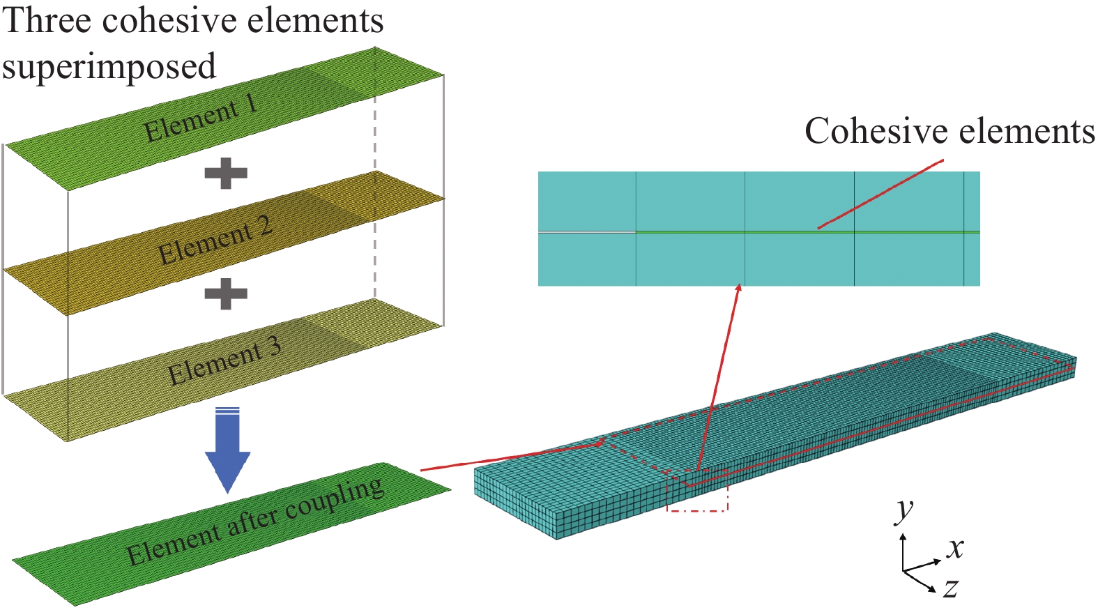
摘要: 分层损伤是航空航天复合材料结构分层的主要损伤模式之一。I型分层具有起始断裂韧性值低,损伤模式复杂的特征,深入分析裂纹尖端损伤区多种损伤机制之间的相互关系,及纤维桥接损伤演化过程,对研究I型分层损伤起关键作用。本文针对性采用三种不同层间铺层(0//0,0//45,0//90)设计T700级碳纤维/环氧复合材料层合板并开展I型分层测试。通过观测分层起始以及损伤演化过程,总结DCB试验结果载荷位移曲线及R曲线规律,并根据试样断口形貌、SEM等多种表征方法分析,揭示了裂纹尖端的损伤机制。在此基础上提出了一种分层损伤机制解耦的新方法。该方法基于三个双线性内聚力本构叠加,通过建立内聚力单元模型来解耦不同损伤尺度的分层损伤机制,独立表征了不同损伤机制在分层扩展过程中所作的贡献。仿真模拟所需参数均可从试验获得,计算得到的仿真结果与试验结果具有良好的一致性。Abstract: Delamination damage is one of the primary damage modes in aerospace composite structures. Mode I delamination exhibits characteristics of low initial fracture toughness and complex damage patterns. Analyzing the interrelationships among three damage mechanisms at the crack tip region and bridging fiber damage evolution plays a crucial role in studying Mode I delamination. This paper specifically designs T700 level carbon fiber/epoxy composite laminates with three different interlayer configurations (0//0, 0//45, 0//90) and conducts Mode I delamination tests. By observing the initiation and evolution of delamination, summarizing DCB experimental results in load-displacement curves and R-curves, and employing various characterization methods like SEM analysis based on specimen fracture surfaces, it reveals the damage mechanisms at the crack tip. Subsequently, a new approach to decoupling layered damage mechanisms is proposed, based on three bilinear cohesive constitutive laws. This method establishes a cohesive element model to decouple layered damage mechanisms at different damage scales, independently characterizing the contributions of different damage mechanisms during layered propagation. Parameters required for simulation are obtained from experiments, and the simulated results exhibit good consistency with experimental data.
-
Key words:
- composite laminates /
- delamination /
- fiber bridging /
- damage mechanism /
- double cantilever beam /
- cohesive zone model
-
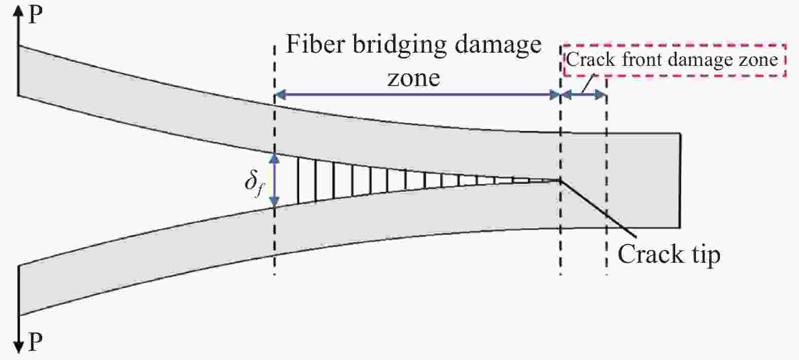
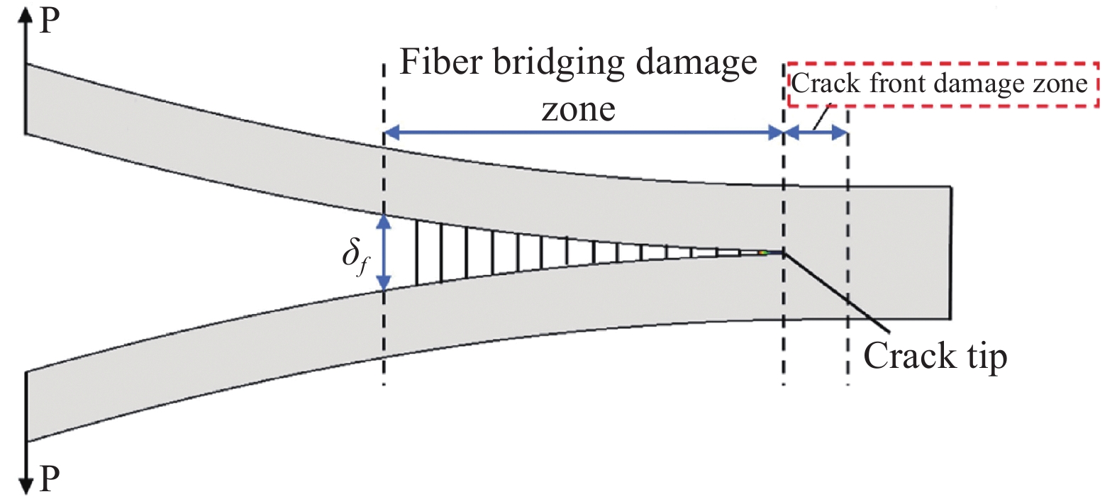
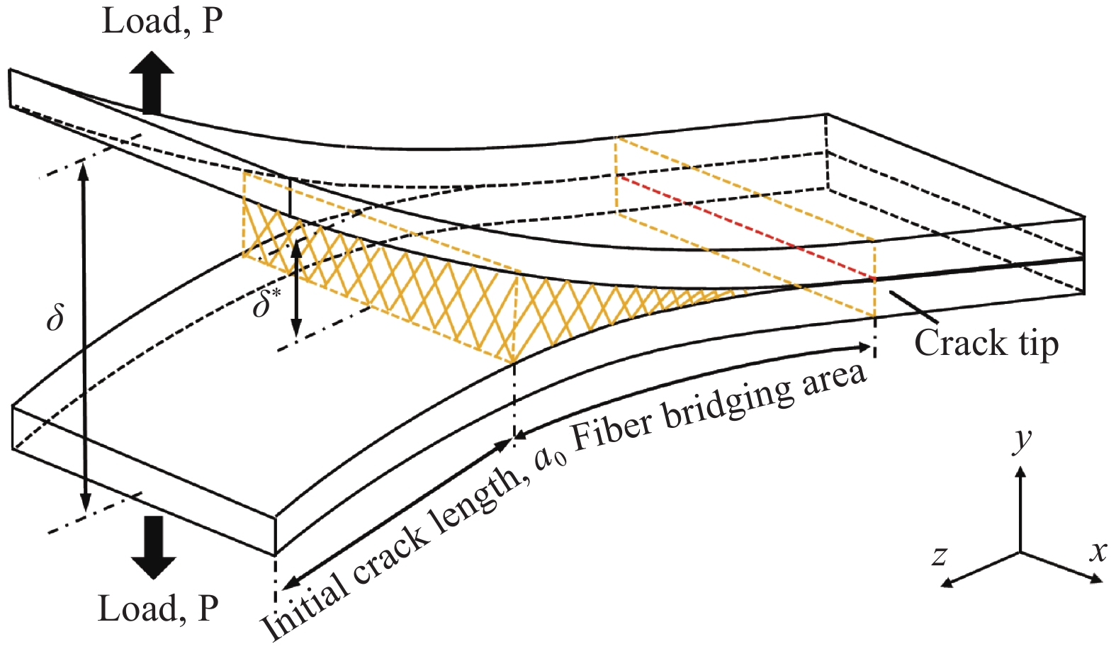
图 3 DCB试验纤维桥接损伤区和裂纹尖端损伤区示意图
Figure 3. Sketch of the double cantilever beam (DCB) test fiber bridging damage zone and crack front damage zone
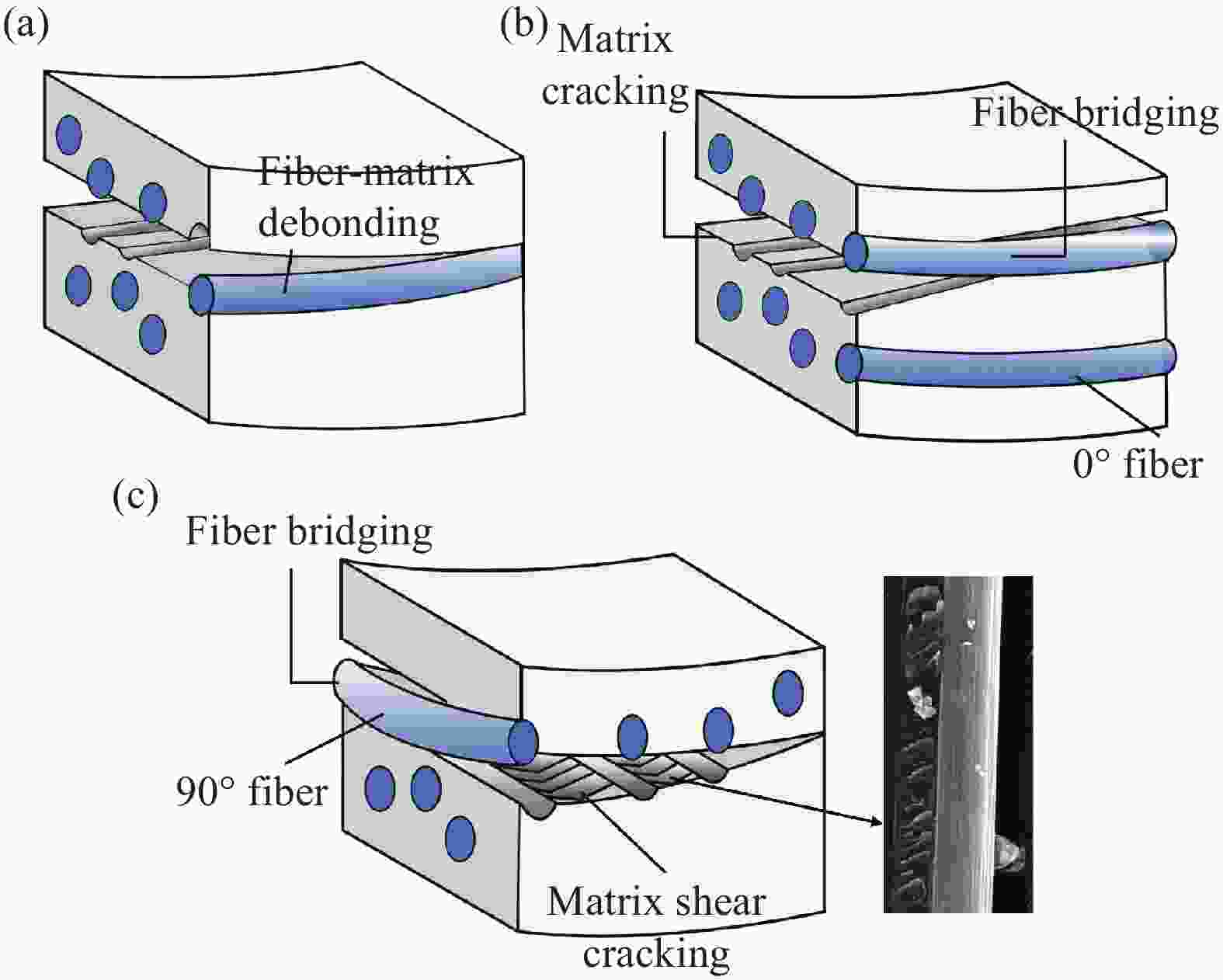
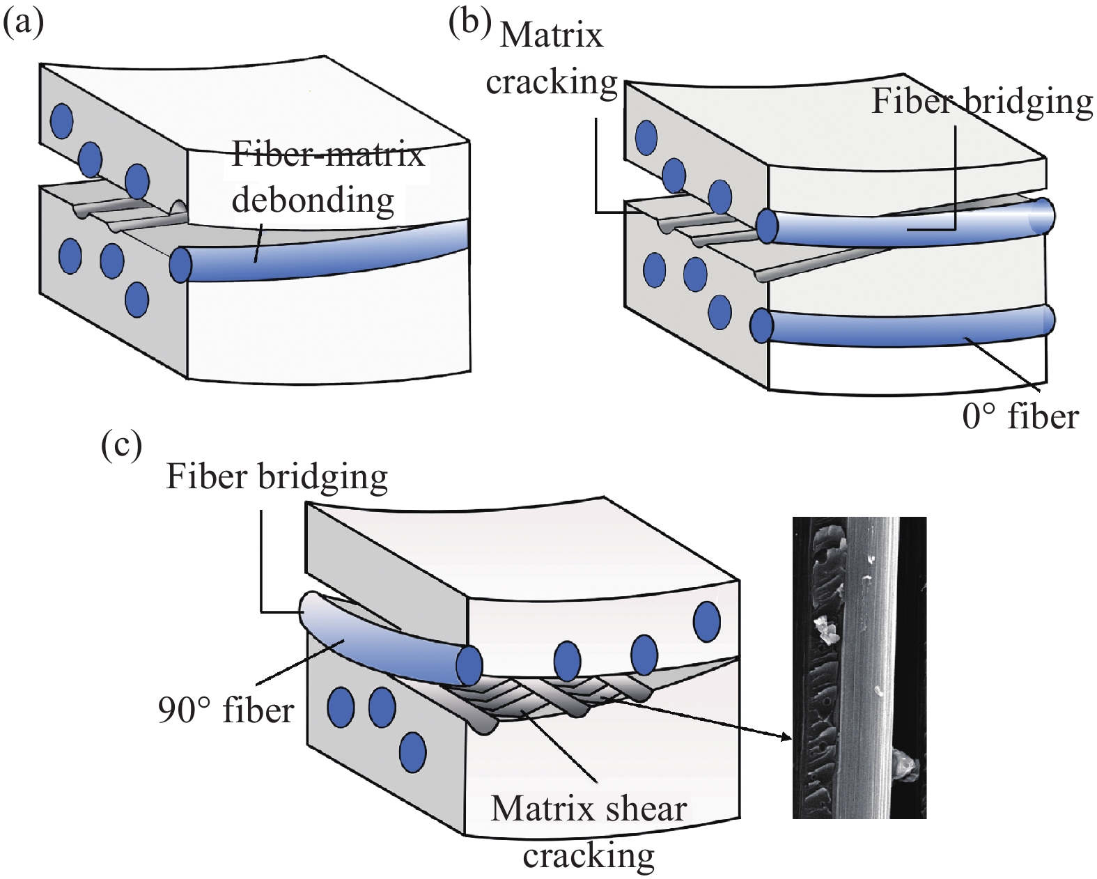
图 4 裂纹尖端损伤区损伤机制示意图:(a) 0//0铺层角度基体开裂和基体/纤维分离;(b) 0//0铺层角度基体/纤维分离导致的纤维桥接和错位裂纹;(c) 0//90铺层角度基体剪切开裂和纤维桥接
Figure 4. Schematic diagram of damage mechanism in crack tip damage zone: (a) 0//0 ply angle matrix cracking and matrix/fiber separation; (b) fiber bridging and dislocation cracks caused by 0//0 ply angle matrix/fiber separation; (c) 0//90 ply angle matrix shear cracking and fiber bridging
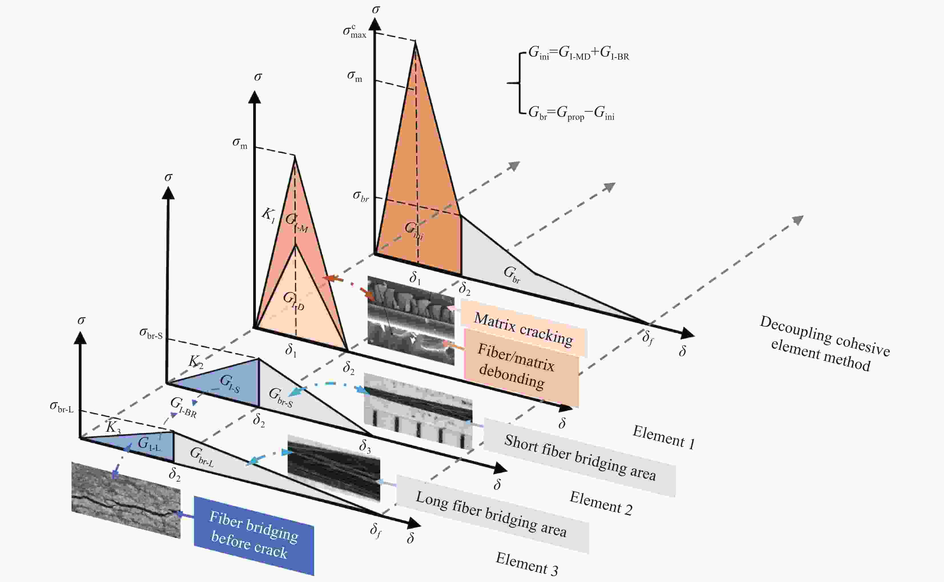
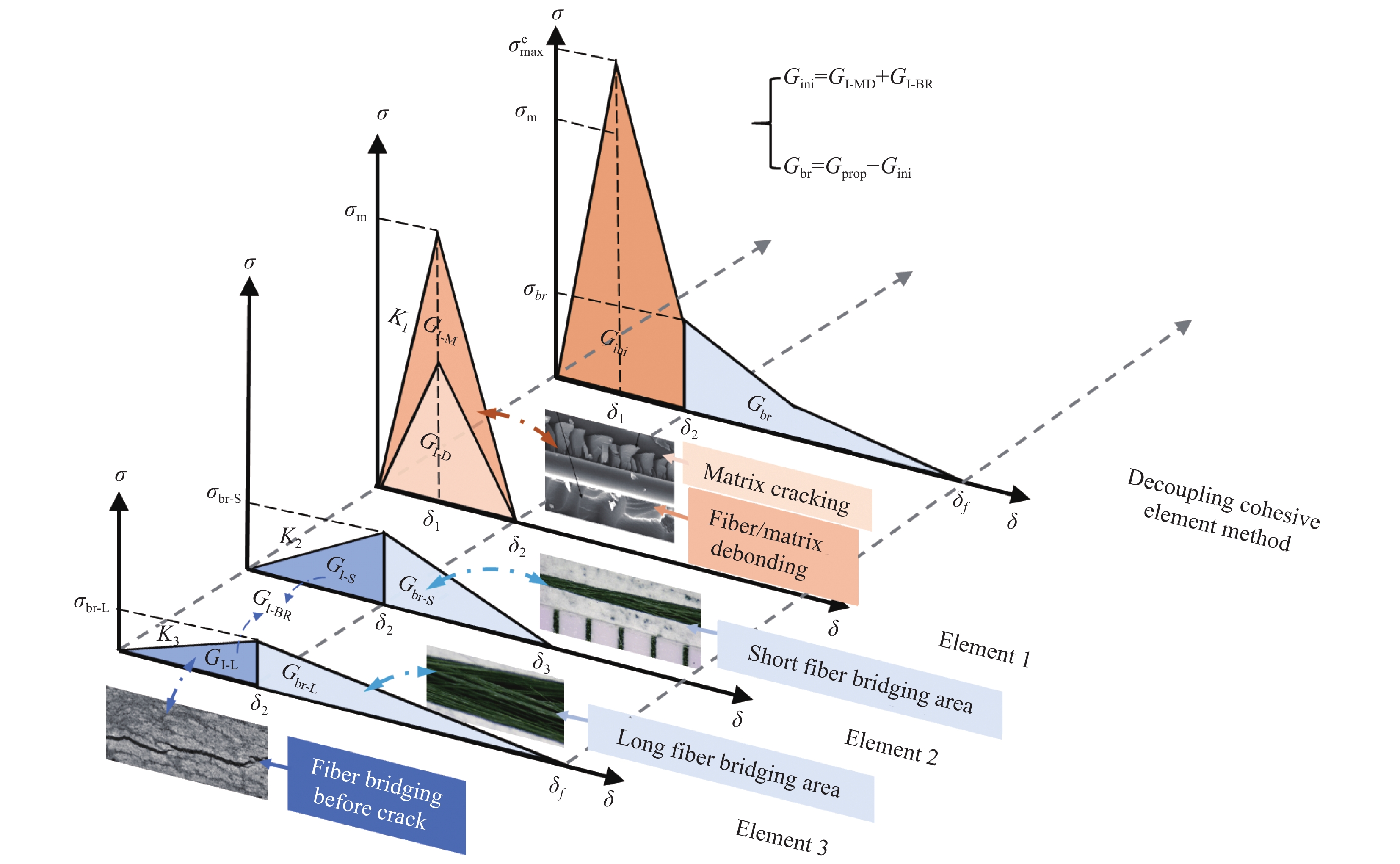
图 6 解耦内聚力本构示意图
Figure 6. Decoupling cohesive force constitutive diagram
${G_{{\text{prop}}}}$−Steady-state strain energy release rate; ${G_{{\text{ini}}}}$−Initial strain energy release rate; ${G_{{\text{br}}}}$−Strain energy release rate of fiber bridging; $ {\sigma _{{\text{br}}}} $−Maximum bridge stress; $ {\delta _{{\text{br}}}} $−Maximum bridge displacement; $ {\sigma _{\text{m}}} $−Matrix damage strength; $ \sigma _{\text{m}}^{\text{c}} $−Maximum stress after coupling; ${\delta _1}$−Critical displacement at which the matrix damage strength is reached; ${\delta _2}$−Opening displacement of cohesive elements in the matrix when they completely fail; ${\delta _3}$−Maximum displacement in the short fiber bridging area; ${G_{{\text{I-MD}}}}$−Overall strain energy release rate of Element 1; ${G_{{\text{I-M}}}}$−Strain energy release rate of matrix fracture; ${G_{{\text{I-D}}}}$−Strain energy release rate of matrix fiber separation at the same interface without dislocation; ${G_{{\text{I-BR}}}}$−Strain energy release rate of fiber bridging formed by dislocation separation of matrix and fibers; ${G_{{\text{br-L}}}}$−Strain energy release rate in the long fiber bridging area; ${G_{{\text{br-S}}}}$−Strain energy release rate in the short fiber bridging area;$ {\sigma _{{\text{br-L}}}} $−Maximum bridging stress in the long fiber bridging area; $ {\sigma _{\text{br-S}}} $-Maximum bridging stress in the short fiber bridging area; $ {\delta _{\text{f}}} $-Maximum opening displacement of the overall bridging fiber zone at the crack tip; ${G_{{\text{I-L}}}}$-Release rate of strain energy for the separation of basic fibers in the long fiber bridging area; ${G_{{\text{I-S}}}}$-Release rate of strain energy for the separation of basic fibers in the short fiber bridging area; ${K_1}$-Initial interface stiffness of cohesive element for matrix cracking; ${K_2}$-Stiffness of cohesive elements in the short fiber bridging area; ${K_3}$-Stiffness of cohesive elements in the long fiber bridging area
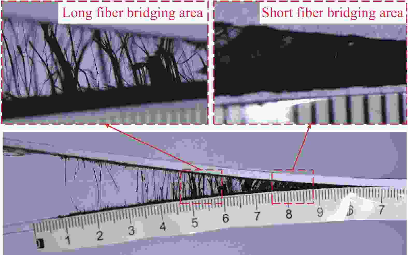
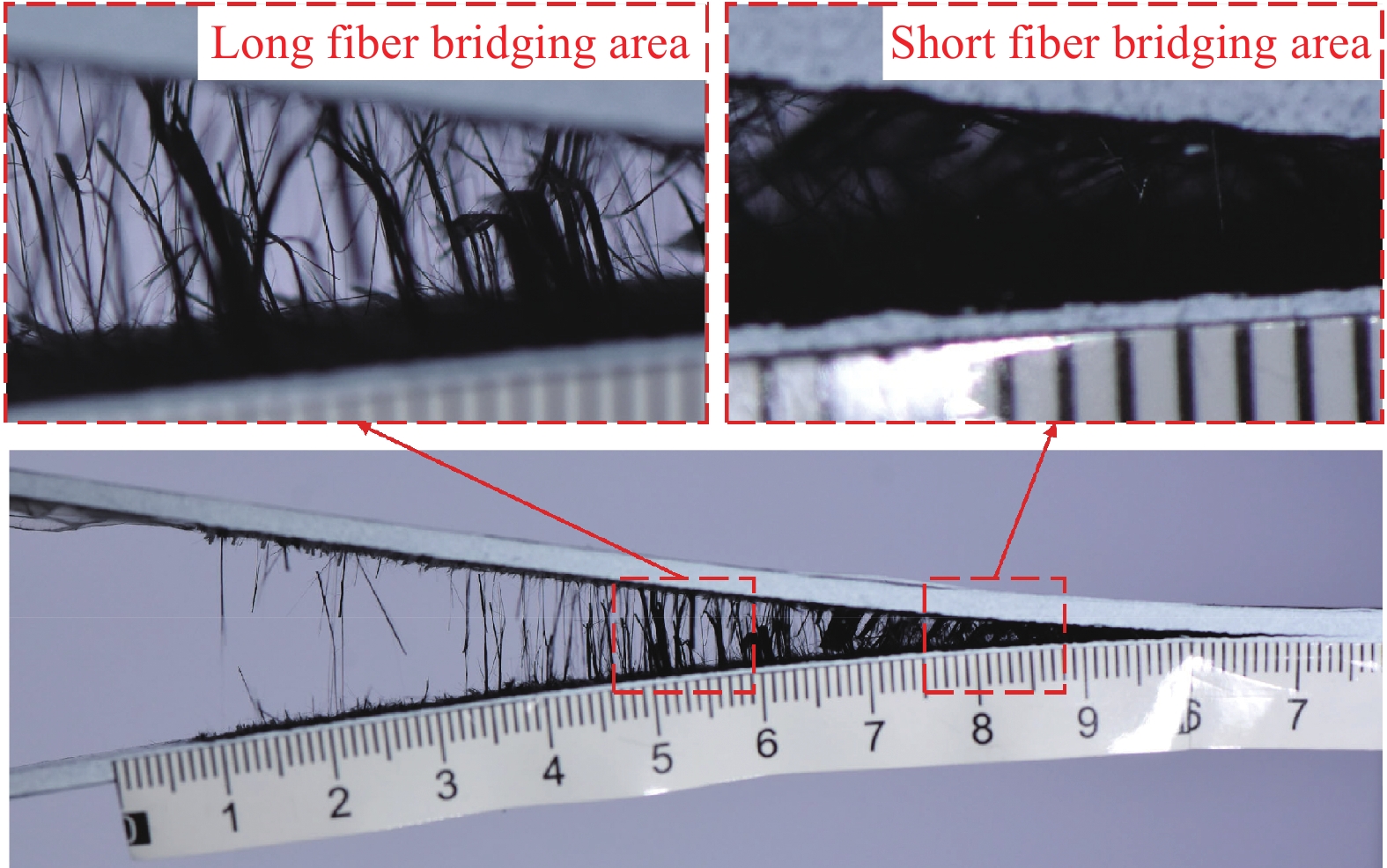
图 7 DCB试样纤维桥接区域图:(a)长纤维区;(b)短纤维区
Figure 7. DCB sample fiber bridging area diagram: (a) Long fiber bridging area; (b) Short fiber bridging area
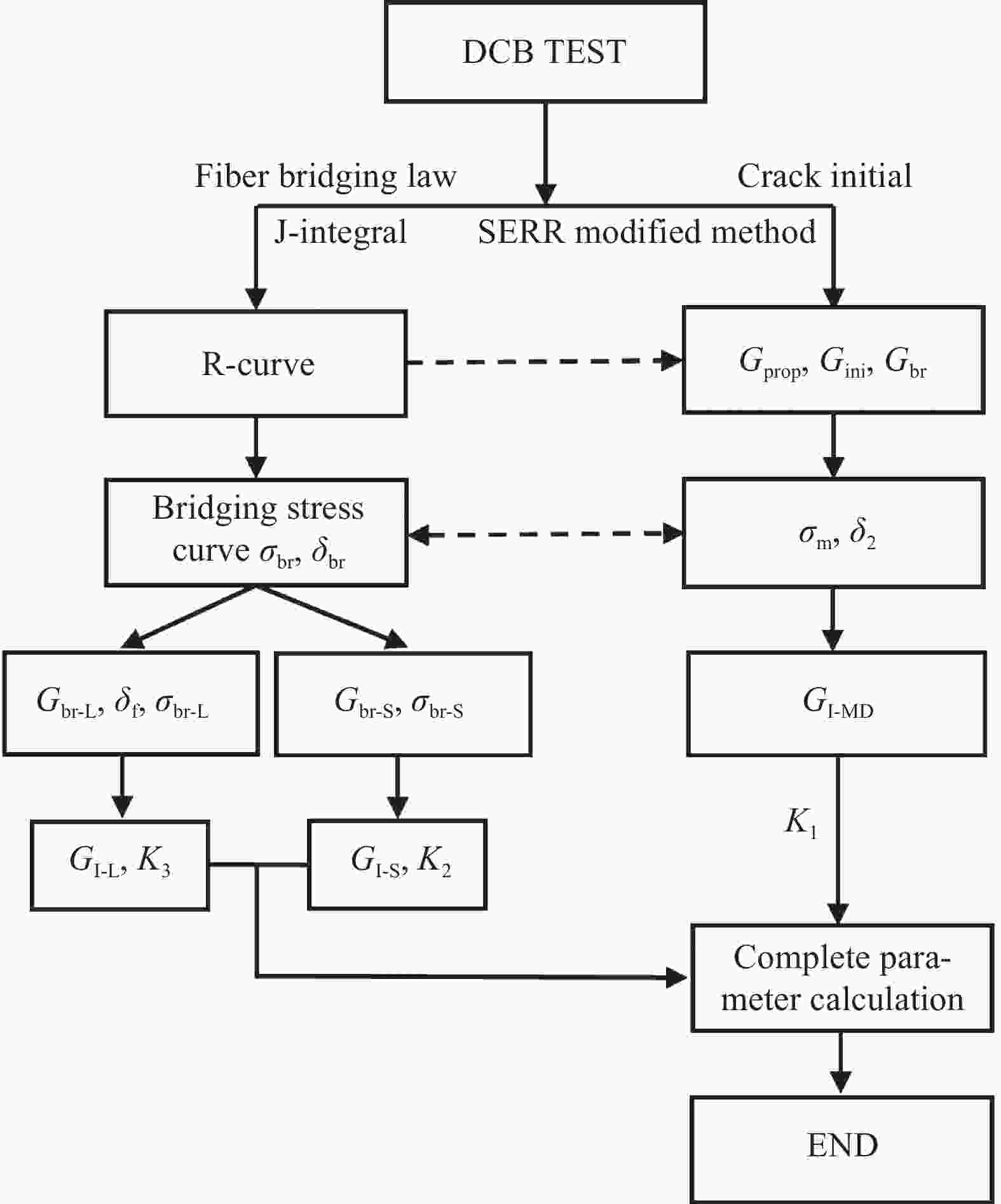
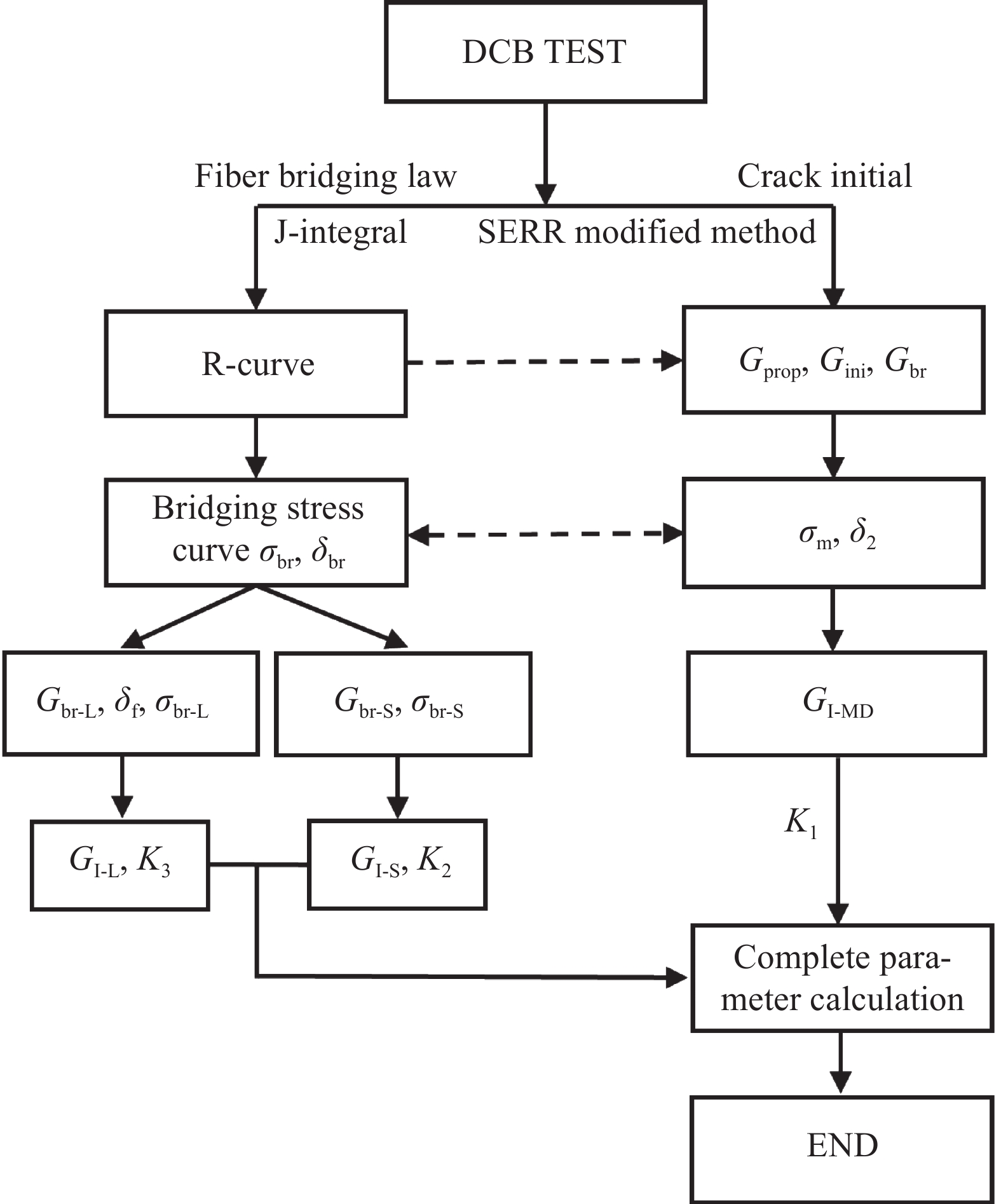
图 9 计算解耦内聚力方法参数流程图
Figure 9. Parameter flowchart for calculating decoupling cohesive method
${G_{{\text{prop}}}}$−Steady-state strain energy release rate;${G_{{\text{ini}}}}$−Initial strain energy release rate; ${G_{{\text{br}}}}$−Strain energy release rate of fiber bridging; $ {\sigma _{{\text{br}}}} $−Maximum bridge stress; $ {\delta _{{\text{br}}}} $−Maximum bridge displacement; $ {\sigma _{\text{m}}} $−Matrix damage strength; ${\delta _2}$−Opening displacement of cohesive elements in the matrix when they completely fail; ${G_{{\text{I - MD}}}}$−Overall strain energy release rate of Element 1; ${G_{{\text{br - L}}}}$−Strain energy release rate in the long fiber bridging area; ${G_{{\text{br - S}}}}$−Strain energy release rate in the short fiber bridging area; $ {\sigma _{{\text{br - L}}}} $−Maximum bridging stress in the long fiber bridging area; $ {\sigma _{br - S}} $-Maximum bridging stress in the short fiber bridging area; $ {\delta _{\text{f}}} $-Maximum opening displacement of the overall bridging fiber zone at the crack tip; ${G_{{\text{I - L}}}}$-Release rate of strain energy for the separation of basic fibers in the long fiber bridging area; ${G_{{\text{I - S}}}}$-Release rate of strain energy for the separation of basic fibers in the short fiber bridging area; ${K_1}$-Initial interface stiffness of cohesive element for matrix cracking; ${K_2}$-Stiffness of cohesive elements in the short fiber bridging area; ${K_3}$-Stiffness of cohesive elements in the long fiber bridging area
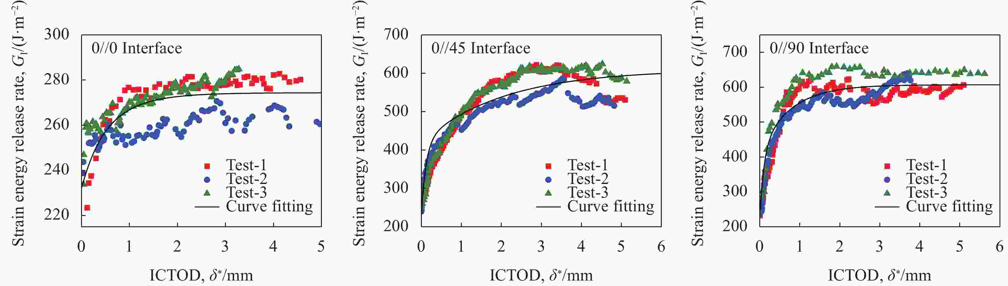
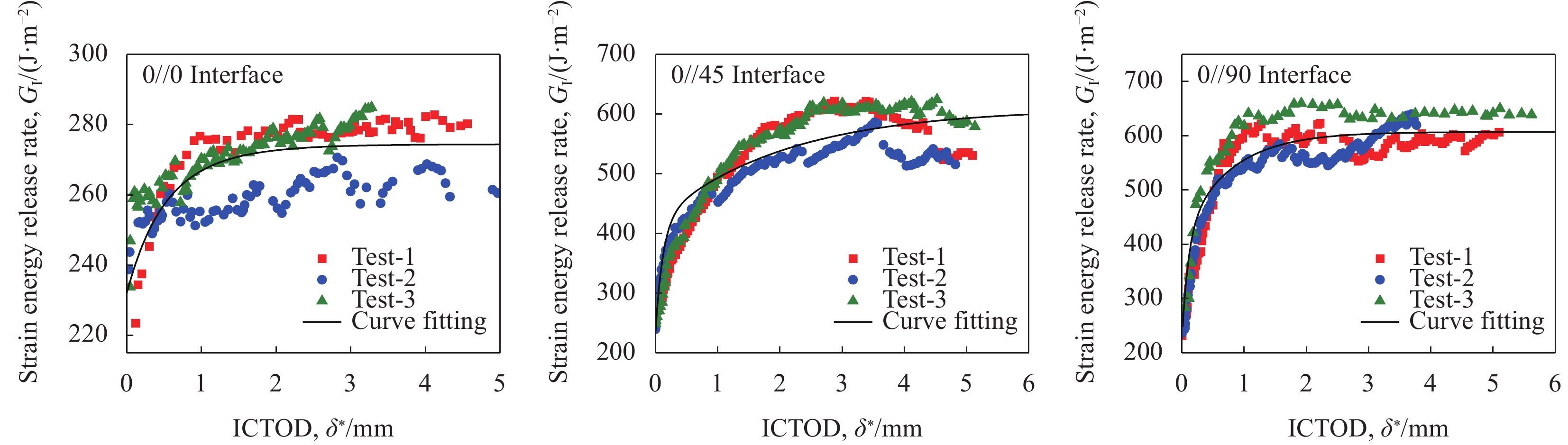
图 10 不同层间铺层角度下DCB试样的应变能释放率与ICTOD的关系
Figure 10. Relationship between strain energy release rate and ICTOD of DCB specimens with different interlayer angles

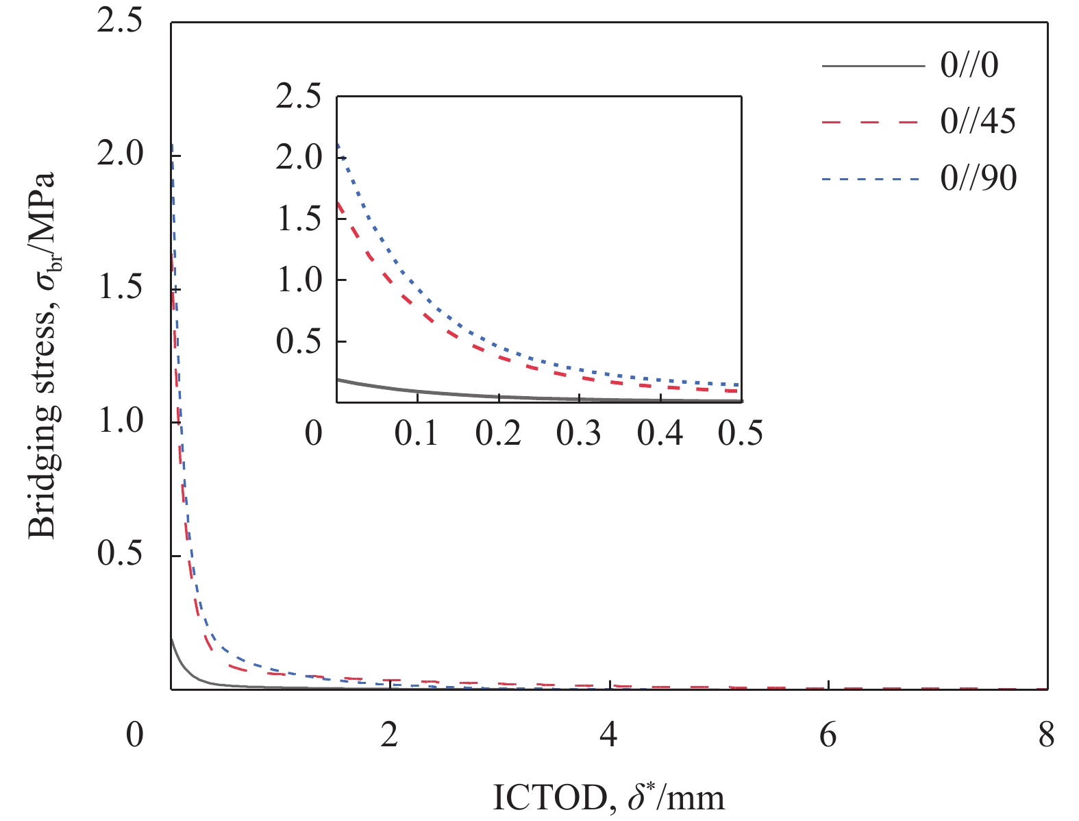
图 11 不同层间铺层角度下DCB试样的桥接分布规律
Figure 11. Distribution patterns of bridging of DCB specimens at different interlaminar ply angles
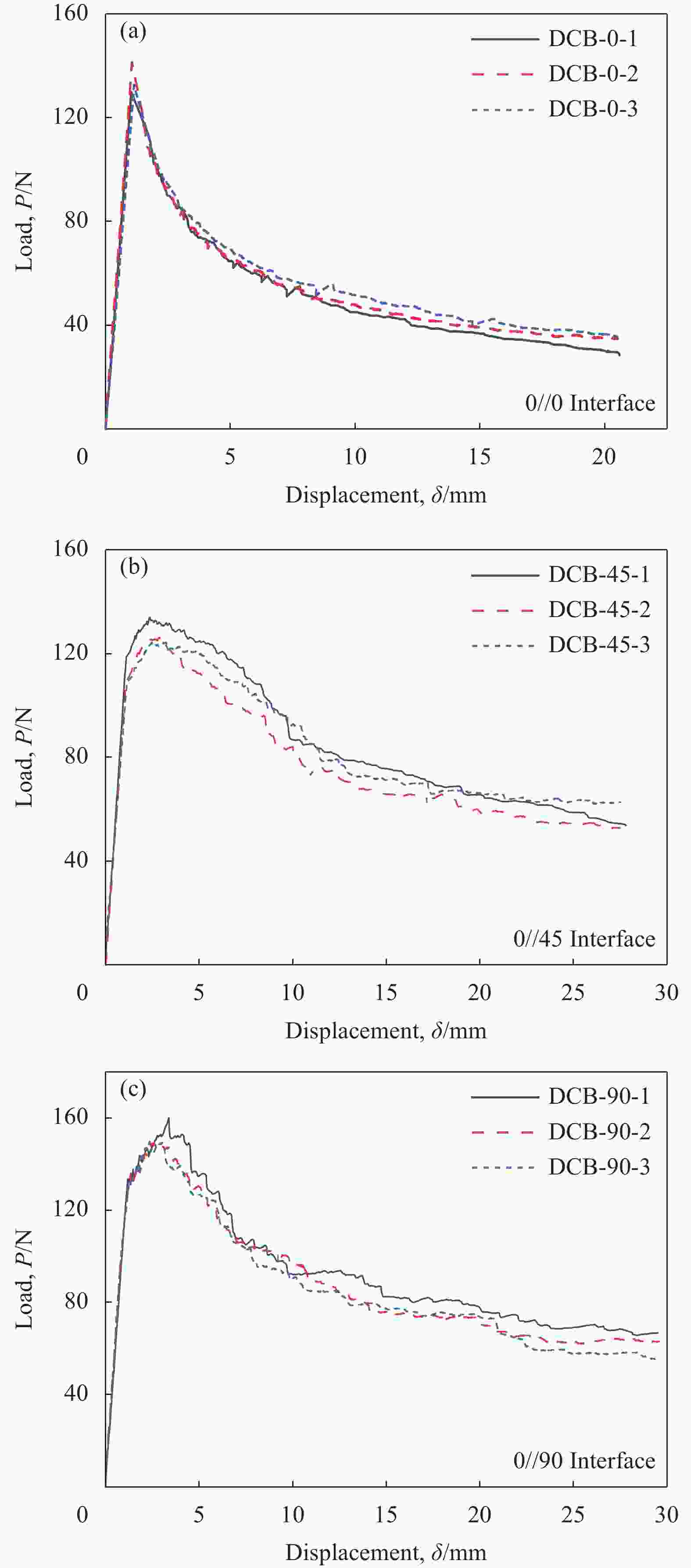
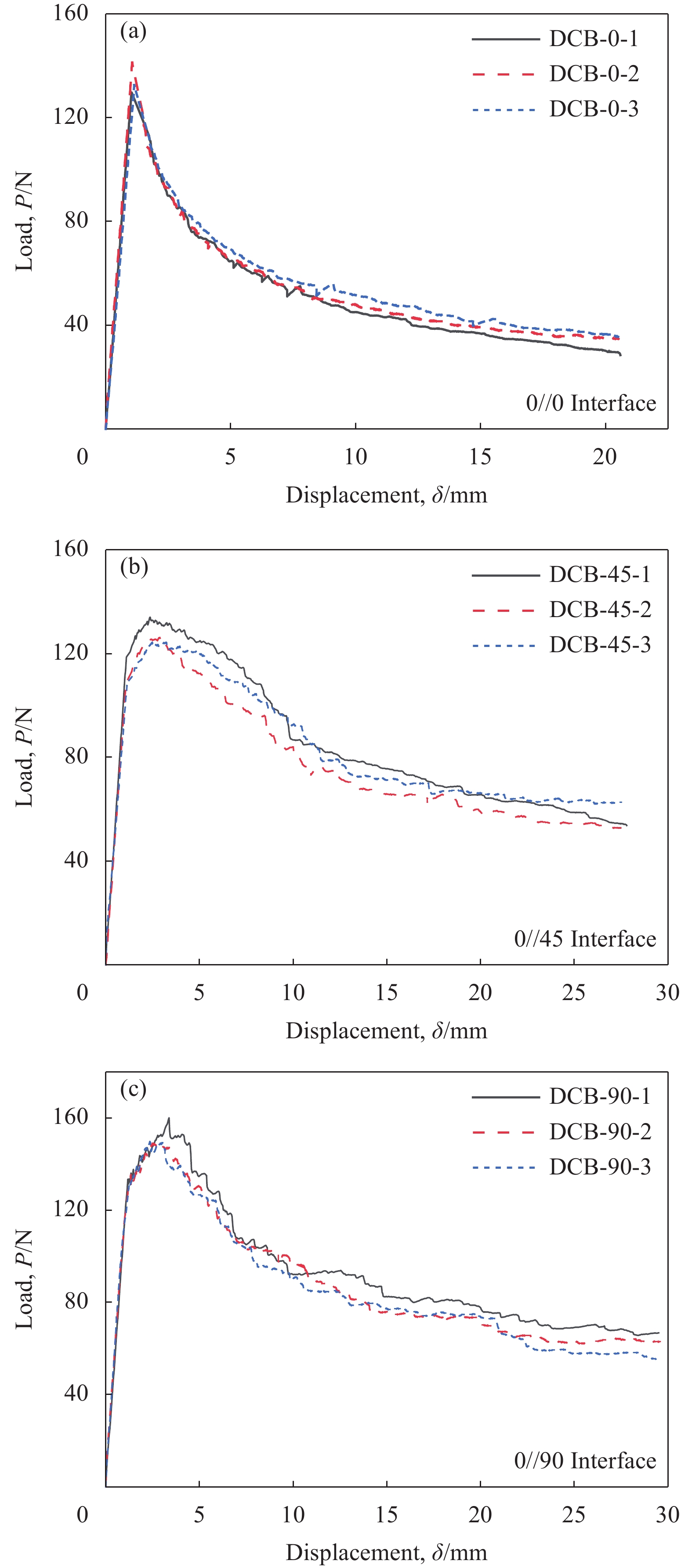
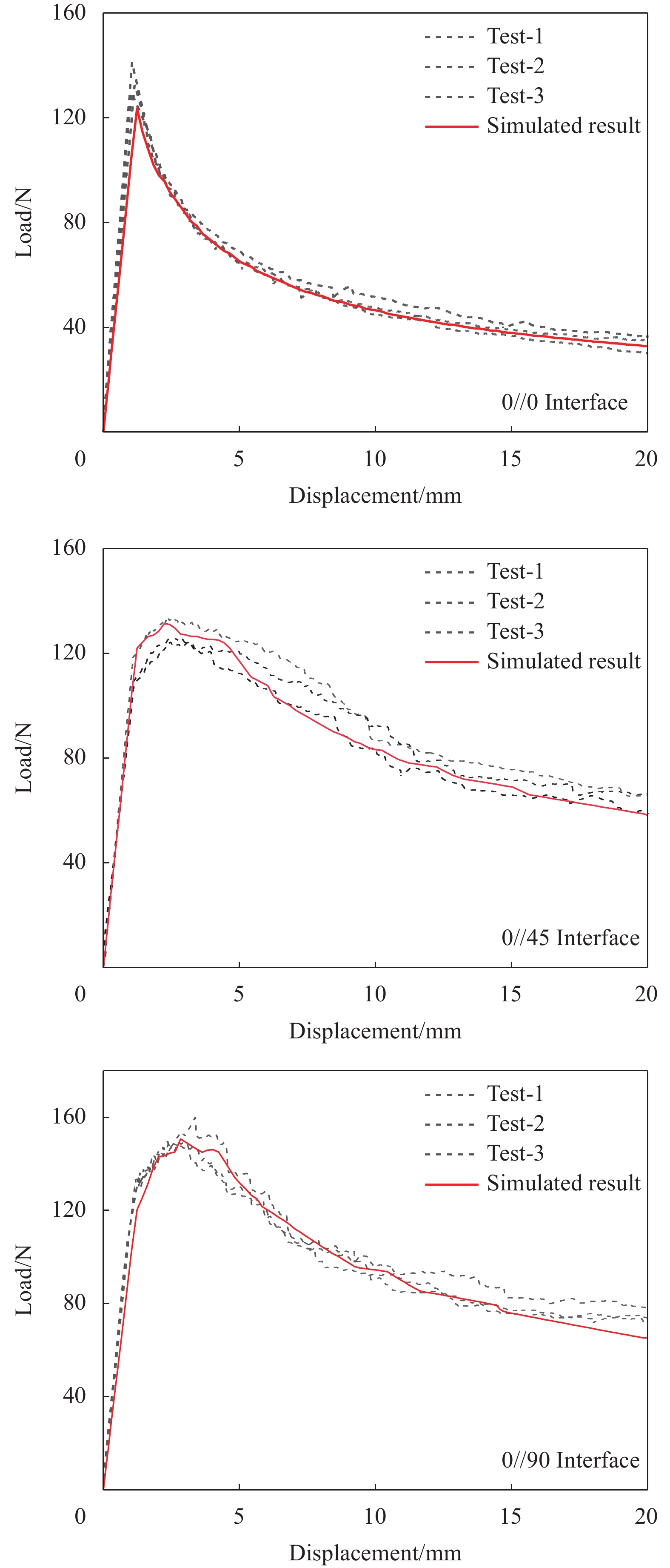
图 12 不同层间铺层角度下DCB试样的载荷-位移曲线:(a)0//0;(b)0//45;(c)0//90
Figure 12. Load displacement curves of DCB specimens with different interlayer angles: (a) 0//0; (b) 0//45; (c) 0//90
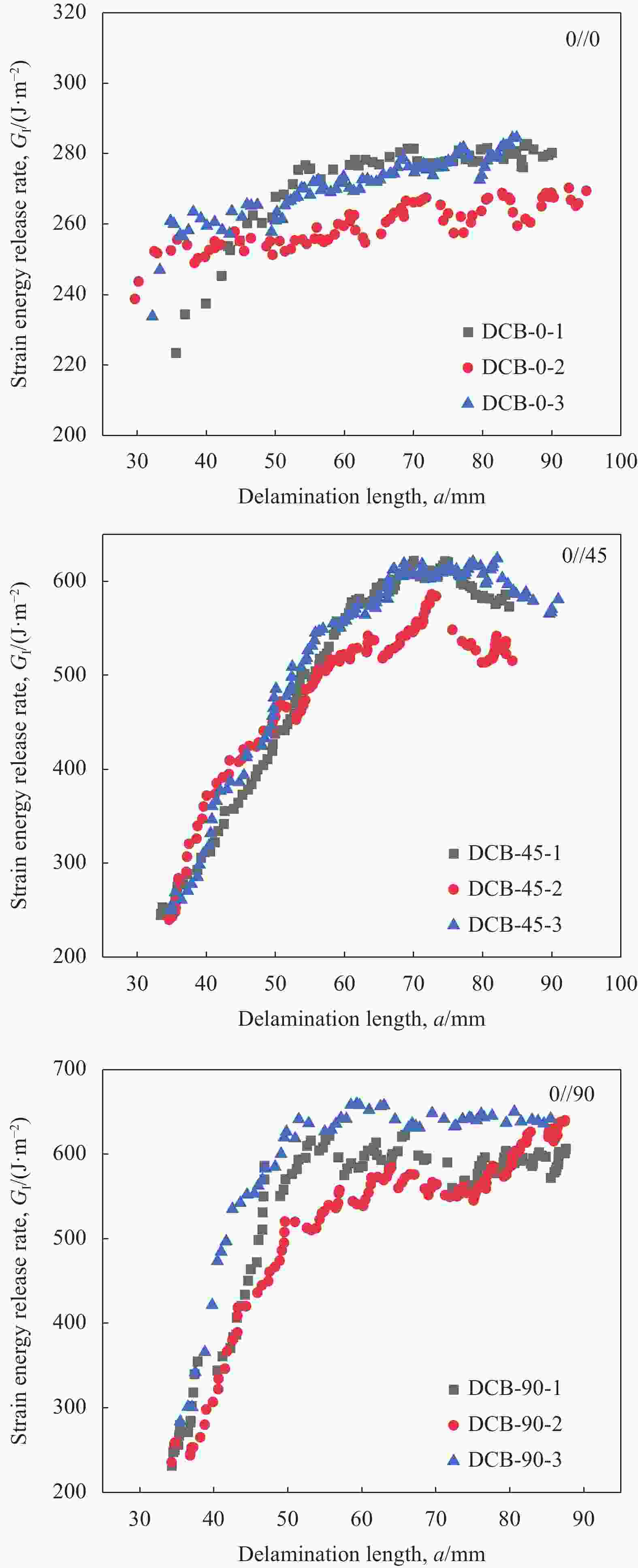
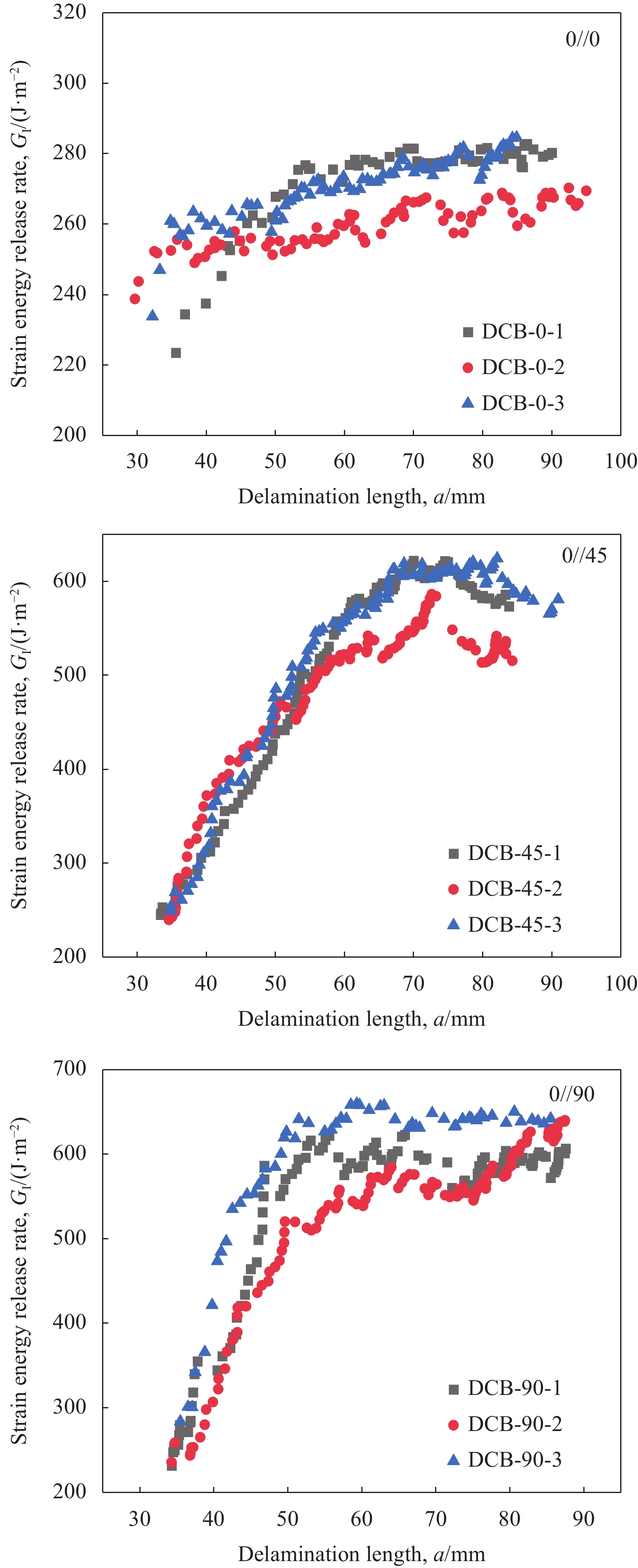
图 13 不同层间铺层角度下DCB试样的R曲线
Figure 13. R-curve of DCB samples with different interlayer angles
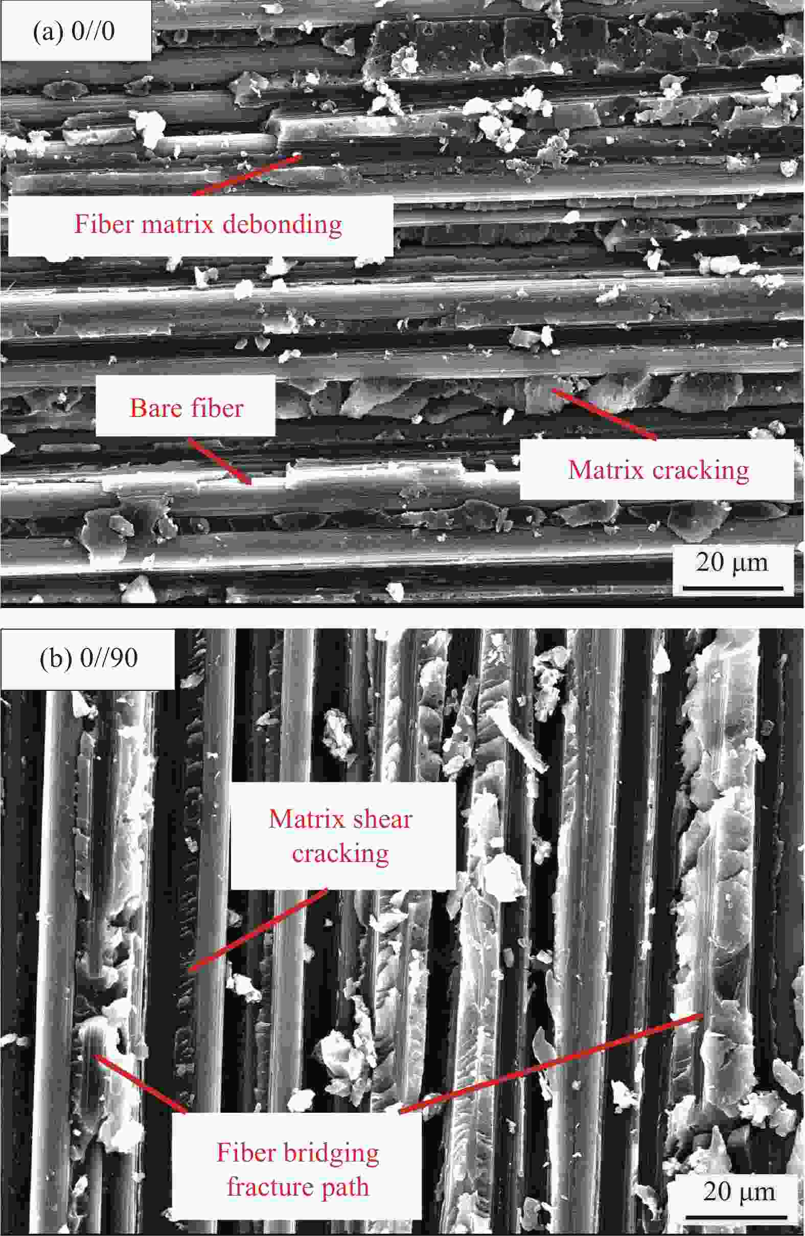
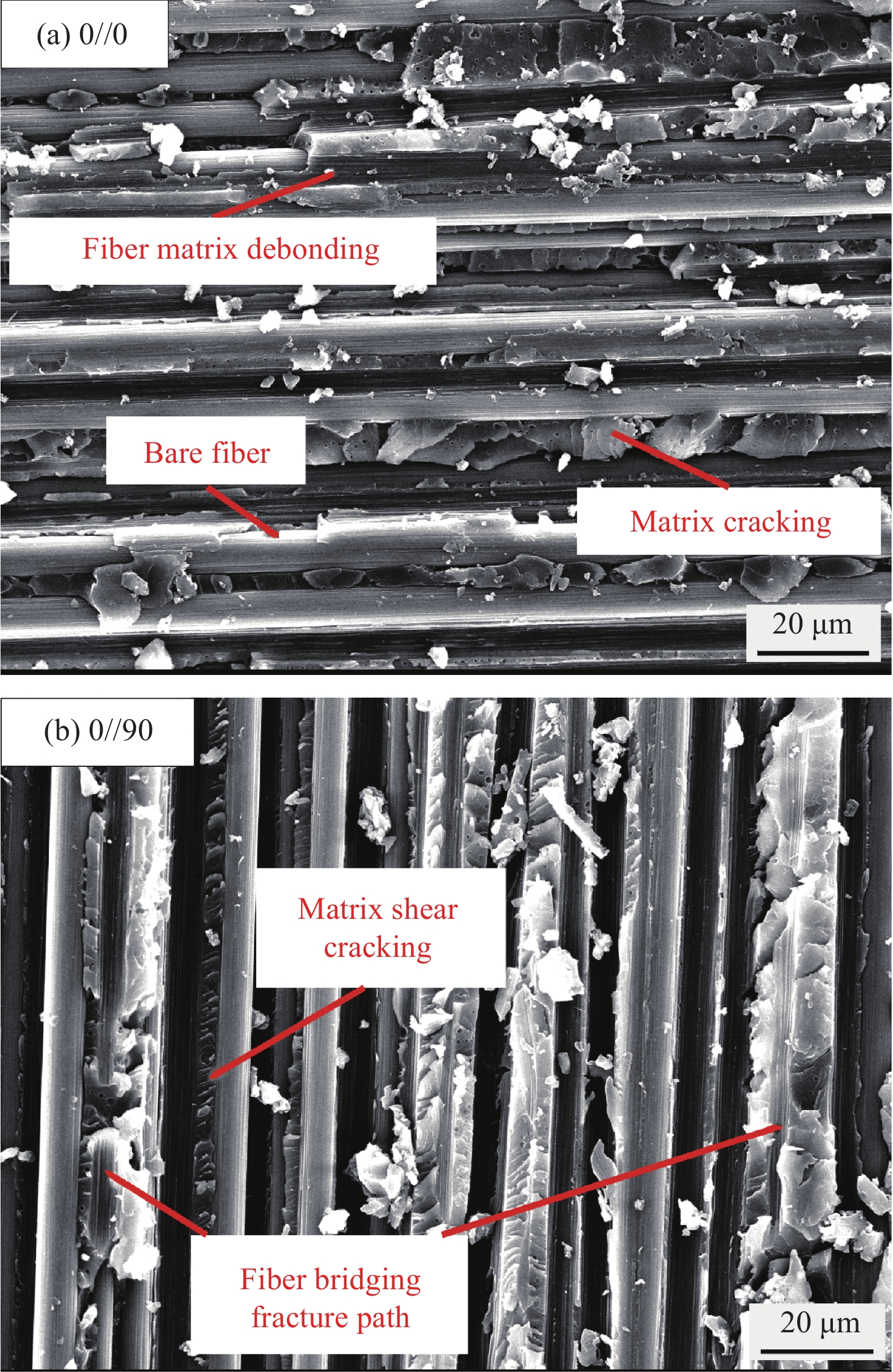
图 14 不同铺层角度下DCB试样分层断面形貌图:(a) 0//0;(b) 0//90
Figure 14. Layered cross-sectional morphology of DCB samples at different layering angles: (a) 0//0; (b) 0//90
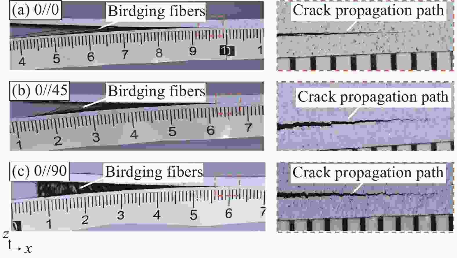
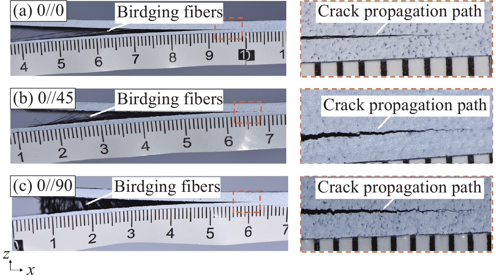
图 15 各铺层角度下DCB试样分层扩展路径及纤维桥接现象侧视图
Figure 15. Side view of the delamination propagation path and fiber bridging phenomenon of DCB samples at different ply angles
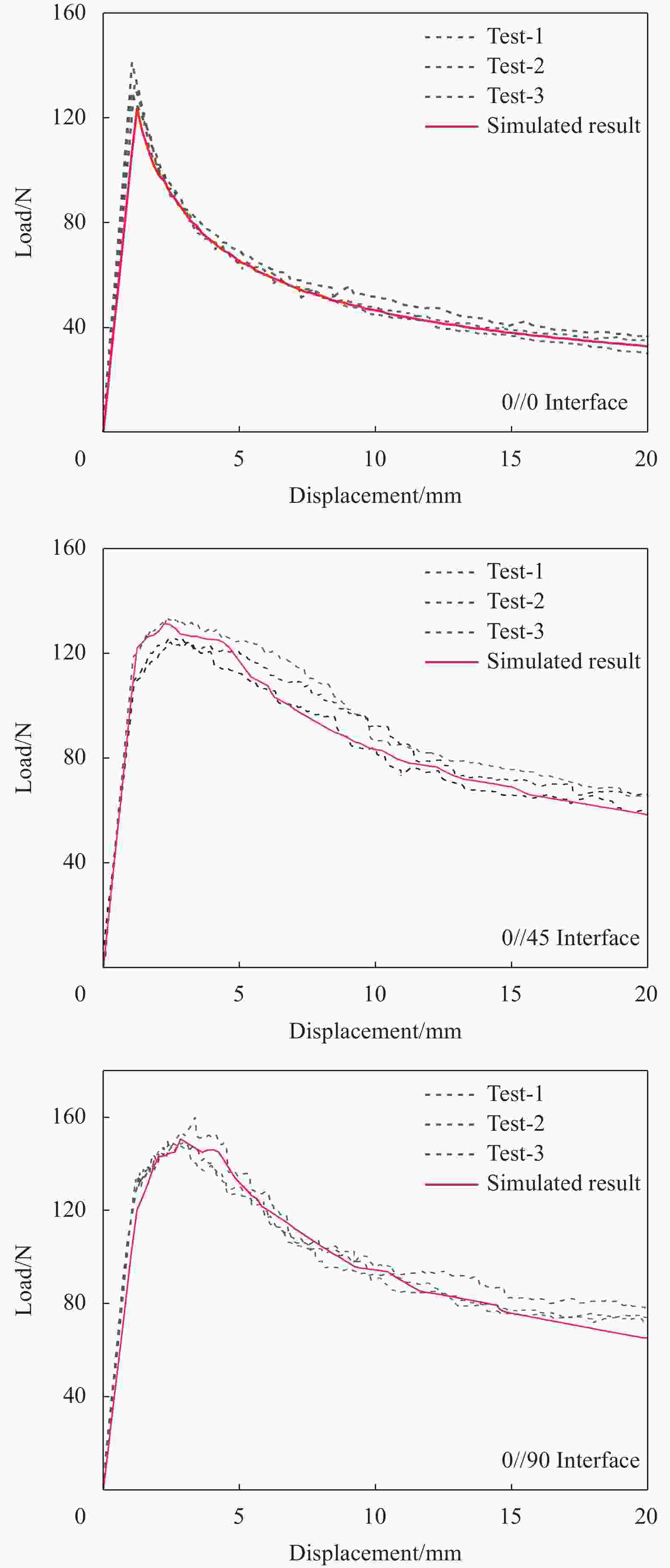
图 16 不同铺层角度下DCB试样的仿真结果
Figure 16. Simulation results of DCB samples with different layering angles
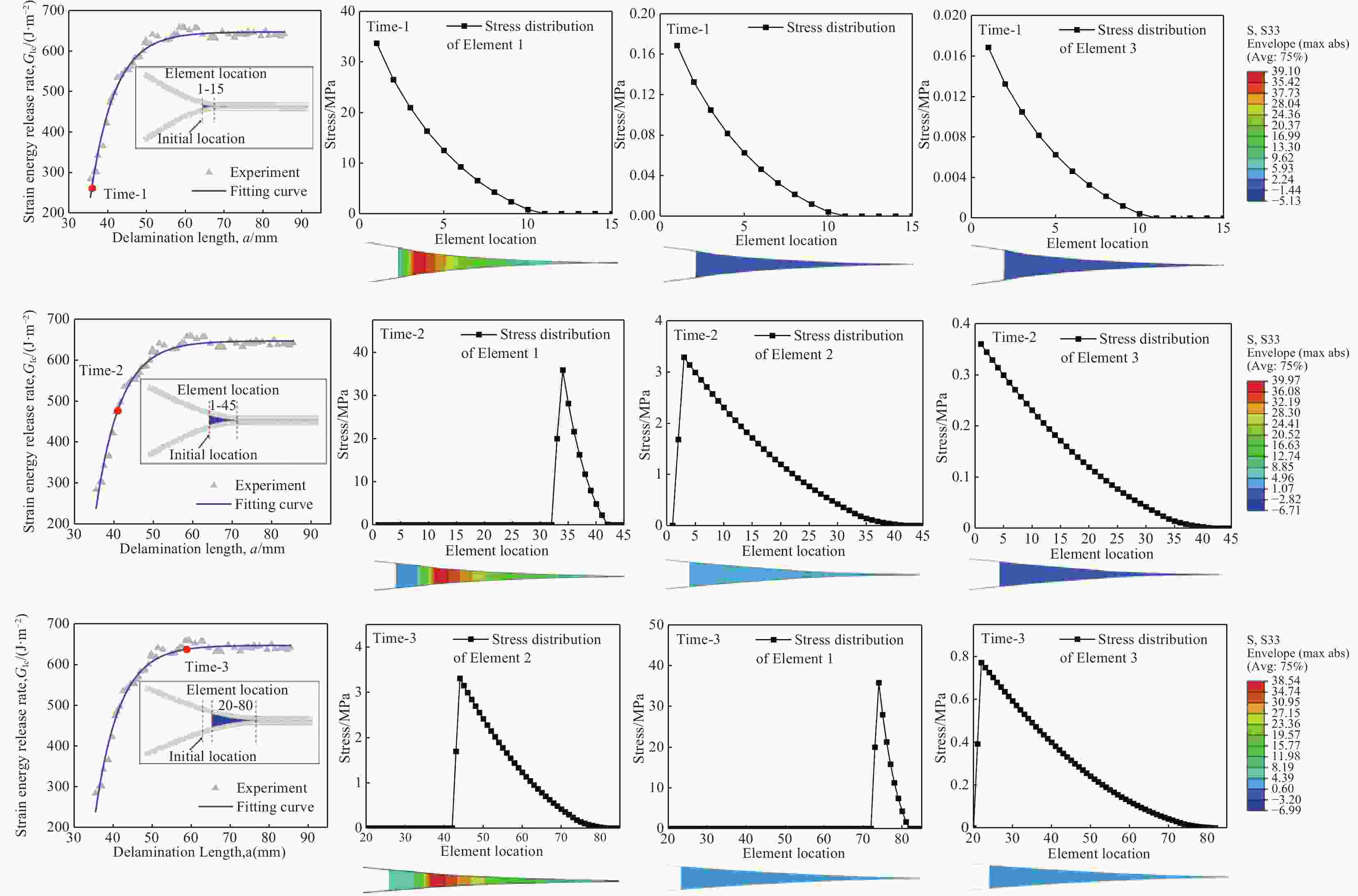
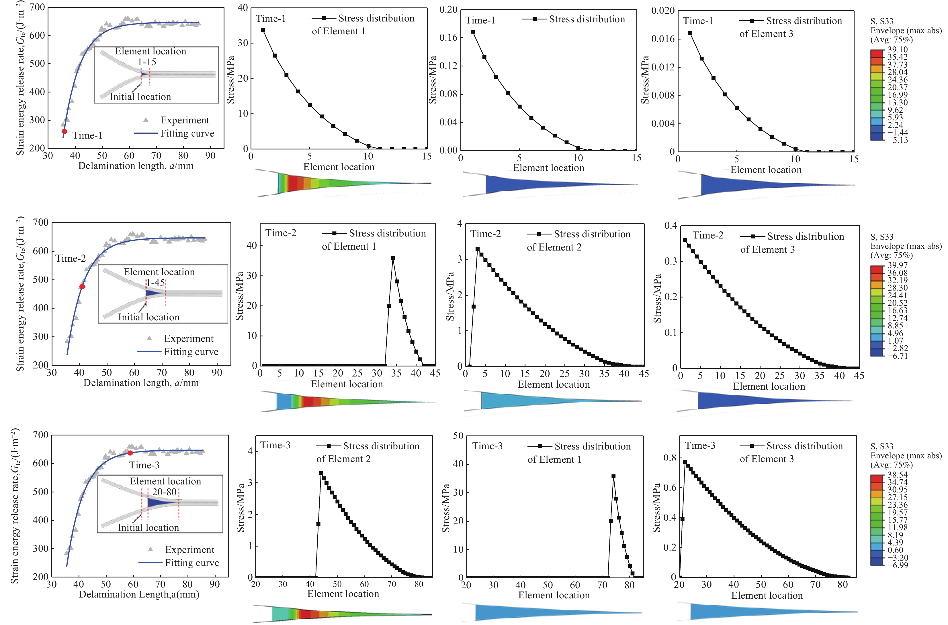
图 17 同一时刻下不同内聚力单元应力分布图
Figure 17. Stress distribution diagram of different cohesive element at the same time
表 1 T700级碳纤维/环氧树脂复合材料层合板基础力学性能
Table 1. Mechanical properties of T700 level carbon fiber/epoxy resin composite laminate foundation
Parameter Value E11/GPa 117 E22/GPa 7.47 E33/GPa 7.47 ν12 0.33 ν13 0.33 ν23 0.3 G12/GPa 4.07 G13/GPa 4.07 G23/GPa 2.31 Notes: E−Elastic modulus; ν−Poisson’s ratio; G−Shear modulus; 1−Direction of fiber; 2−Direction of matrix; 3−Thickness direction of layer.  下载: 导出CSV
表 2 不同层间铺层角度下DCB试样的拟合参数
Table 2. Fitting parameters of DCB specimens at different interlaminar ply angles
Interface ${G_{\text{a}}}$/(J·m−2) ${G_{\text{b}}}$/(J·m−2) ${\delta _{\text{a}}}$/mm $ {\delta _{\text{b}}} $/mm $ {\sigma _{{\text{br}}}} $/MPa $ {\delta _{{\text{br}}}} $/mm 0//0 20.9 20.5 0.96 0.122 0.18 1.1 0//45 189.7 185 2.05 0.12 1.63 2 0//90 192.7 189.5 0.76 0.102 2.11 0.8 Notes: ${G_{\text{a}}}$; ${G_{\text{b}}}$; ${\delta _{\text{a}}}$; $ {\delta _{\text{b}}} $−Fitting parameters; $ {\sigma _{{\text{br}}}} $−Maximum bridge stress; $ {\delta _{{\text{br}}}} $−Maximum bridge displacement.
下载: 导出CSV
表 3 不同层间铺层角度下DCB试样层间断裂韧性
Table 3. Interlaminar Fracture toughness of DCB specimens at different interlaminar ply angles
Delamination interface No. Delamination Toughness/(J·m−2) Average value/(J·m−2) $G_{\text{I}}^{{\text{ini}}}$ $ G_{\text{I}}^{{\text{prop}}} $ 0//0 DCB-0-1
DCB-0-2
DCB-0-3223.50
238.75
233.77279.22
261.44
273.19232.01 271.28 0//45 DCB-45-1
DCB-45-2
DCB-45-3245.91
241.17
251.79605.72
536.17
604.24246.29 582.04 0//90 DCB-90-1
DCB-90-2
DCB-90-3237.61
246.08
283.79588.72
562.36
651.04255.83 600.71 Notes: $G_{\text{I}}^{{\text{ini}}}$−Initial interlayer fracture toughness value; $ G_{\text{I}}^{{\text{prop}}} $−Steady state interlayer fracture toughness value; Naming method for sample number: DCB-0-1−Test method-Layer angle-Number.
下载: 导出CSV
-
[1] 杜善义, 关志东. 我国大型客机先进复合材料技术应对策略思考[J]. 复合材料学报, 2008, 25(1): 10.DU S, GUAN Z. Strategic considerations for development of advanced composite technology for large commercial aircraft in China[J]. Acta Materiae Compositae Sinica, 2008, 25(1): 1-10 (in Chinese). [2] Beaumont P W R , Soutis C . The Structural Integrity of Carbon Fiber Composites, Fifty Years of Progress and Achievement of the Science, Development, and Applications[M]. 2016. [3] 李西宁, 王悦舜, 周新房. 复合材料层合板分层损伤数值模拟方法研究现状[J]. 复合材料学报, 2021, 38(4): 1076-1086.LI Xining, WANG Yueshun, ZHOU Xinfang. Status of numerical simulation methods for delamination damage of composite laminates[J]. Acta Materiae Compositae Sinica, 2021, 38(4): 1076-1086. [4] 赵丽滨, 龚愉, 张建宇. 纤维增强复合材料层合板分层扩展行为研究进展[J]. 航空学报, 2019, 39(1): 1-28ZHAO L, GONG Y, ZHANG J. A survey on delamination growth behavior in fiber reinforced composite laminates[J]. Acta Aeronautica et Astronautica Sinica, 2019, 39(1): 1-28 (in Chinese). [5] Fu Chen, Wang Xi. Simulating delamination in composite laminates involving large scale fiber bridging based on the mixed-mode three-linear cohesive zone model.[J]. Theoretical and Applied Fracture Mechanics, 2022, 117: 103164 doi: 10.1016/j.tafmec.2021.103164 [6] Bin M R M S, Rousseau J, Fontaine S, et al. Experimental study of the influence of ply orientation on DCB mode-I delamination behavior by using multidirectional fully isotropic carbon/epoxy laminates[J]. Composite Structures, 2017, 161: 1-7. doi: 10.1016/j.compstruct.2016.11.036 [7] Sorensen L, Botsis J, Th Gmür, et al. Bridging tractions in mode I delamination: Measurements and simulations[J]. Composites Science and Technology, 2008, 68(12): 2350-2358. doi: 10.1016/j.compscitech.2007.08.024 [8] Sorensen L, Botsis J, Thomas Gmür, et al. Delamination detection and characterisation of bridging tractions using long FBG optical sensors[J]. Composites Part A Applied Science and Manufacturing, 2007, 38(10): 2087-2096. doi: 10.1016/j.compositesa.2007.07.009 [9] Gong Y, Zhang B, Zhao L, et al. R-curve behavior of the mixed-mode Ⅰ/ Ⅱ delamination in carbon/epoxy laminates with unidirectional and multidirectional interfaces[J]. Composite Structures, 2019, 223: 110949.1-110949.8. [10] Bui V Q, Marechal E, Nguyen-Dang H. Imperfect interlaminar interfaces in laminated composites: delamination with the R-curve effect[J]. Composites Science and Technology, 2000, 60(14): 2619-2630. doi: 10.1016/S0266-3538(00)00088-9 [11] Farmand-Ashtiani E, Cugnoni J, Botsis J. Specimen thickness dependence of large scale fiber bridging in mode I interlaminar fracture of carbon epoxy composite[J]. International Journal of Solids and Structures, 2015, 55: 58-65. doi: 10.1016/j.ijsolstr.2014.03.031 [12] Moura M F S F D , Campilho R D S G , Amaro A M , et al. Interlaminar and intralaminar fracture characterization of composites under mode I loading[J]. Composite Structures, 2010, 92(1): 144-149. [13] Bergan A , Davila C , Leone F , et al. A Mode I cohesive law characterization procedure for through-the-thickness crack propagation in composite laminates[J]. Composites Part B Engineering, 2016, 94: 338-349. [14] Pappas G, Botsis J. Intralaminar fracture of unidirectional carbon/epoxy composite: experimental results and numerical analysis[J]. International Journal of Solids and Structures, 2016, 85-86: 114-124 doi: 10.1016/j.ijsolstr.2016.02.007 [15] Shokrieh M M, Daneshjoo Z, Fakoor M. A modified model for simulation of mode I delamination growth in laminated composite materials[J]. Theoretical and Applied Fracture Mechanics, 2016, 82: 107-116 doi: 10.1016/j.tafmec.2015.12.012 [16] Jensen S M, Martos M J, Bak B L V, et al. For mulation of a Mixed-mode Multilinear Cohesive Zone Law in an Interface Finite Element for Modelling Delamination with R-curve Effects[J]. Composite Structures, 2019, 216: 477-486. doi: 10.1016/j.compstruct.2019.02.029 [17] Heidari-Rarani M, Shokrieh M M, Camanho P P. Finite element modeling of mode I delamination growth in laminated DCB specimens with R -curve effects[J]. Composites Part B Engineering, 2013, 45(1): 897-903. doi: 10.1016/j.compositesb.2012.09.051 [18] Vilks V T T. Progressive delamination and fiber bridging modeling in double cantilever beam composite specimens[J]. Engineering Fracture Mechanics, 2001, 68(5): 513-525. doi: 10.1016/S0013-7944(00)00131-4 [19] Alfano G. On the influence of the shape of the interface law on the application of cohesive-zone models[J]. Composites Science and Technology, 2006, 66(6): 723-730. doi: 10.1016/j.compscitech.2004.12.024 [20] Zhao L, Gong Y, Zhang J, et al. Simulation of delamination growth in multidirectional laminates under mode I and mixed mode I/II loadings using cohesive elements[J]. Composite Structures, 2014, 116(9): 509-522. [21] Herráez M, González C, Lopes C S. A numerical framework to analyze fracture in composite materials: from R-curves to homogenized softening laws[J]. International Journal of Solids and Structures, 2018, 134: 216-228 doi: 10.1016/j.ijsolstr.2017.10.031 [22] Farmand-Ashtiani E, Alanis D, Cugnoni J, et al. Delamination in cross-ply laminates: Identification of traction-separation relations and cohesive zone modeling[J]. Composites Science and Technology, 2015, 119: 85-92. doi: 10.1016/j.compscitech.2015.09.025 [23] Canal L P, Pappas G, Botsis J. Large scale fiber bridging in mode I intralaminar fracture. An embedded cell approach[J]. Composites Science and Technology, 2016, 126: 52-59. doi: 10.1016/j.compscitech.2016.01.025 [24] Gong Yu, Hou Yixin, Zhao Libin, et al. A modified mode I cohesive zone model for the delamination growth in DCB laminates with the effect of fiber bridging.[J]. International Journal of Mechanical Sciences, 2020, 176: 105514 doi: 10.1016/j.ijmecsci.2020.105514 [25] Shokrieh M M, Salamat-talab M, Heidari-Rarani M. Effect of initial crack length on the measured bridging law of unidirectional E-glass/epoxy double cantilever beam specimens[J]. Materials and Design, 2014, 55(13): 605-611. [26] Tsouvalis N G, Anyfantis K N. Determination of the fracture process zone under Mode I fracture in glass fiber composites[J]. Journal of Composite Materials, 2011, 46(1): 27-41. [27] Shokrieh M M, Salamat-Talab M, Heidari-Rarani M. Dependency of bridging traction of DCB composite specimen on interface fiber angle[J]. Theoretical and Applied Fracture Mechanics, 2017: 22-32. [28] Yin Shihao, Gong Yu, Li Wangchang, et al. A novel four-linear cohesive law for the delamination simulation in composite DCB laminates.[J]. Composites Part B:Engineering, 2020, 180: 107526 doi: 10.1016/j.compositesb.2019.107526 [29] Tan W, Naya, et al. The role of interfacial properties on the intralaminar and interlaminar damage behaviour of unidirectional composite laminates: Experimental characterization and multiscale modelling[J]. Composites Part B:Engineering, 2018, 138: 206-21. doi: 10.1016/j.compositesb.2017.11.043 [30] Ping Hu, Ran Tao, Xiaole Li, et al. Decomposing the coupling damage in mode I multidirectional delamination[J]. Composites Science and Technology, 2022, 229: 109684 doi: 10.1016/j.compscitech.2022.109684 [31] ASTM Standard D5528-13. Standard test method for mode I interlaminar fracture toughness of unidirectional fiber-reinforced polymer matrix composites. ASTM International; 2013 -

 下载:
下载:

 点击查看大图
计量
- 文章访问数: 72
- HTML全文浏览量: 37
- 被引次数: 0
