


Simulation and experimental study of CFRTP orthogonal cutting considering the influence of temperature
-
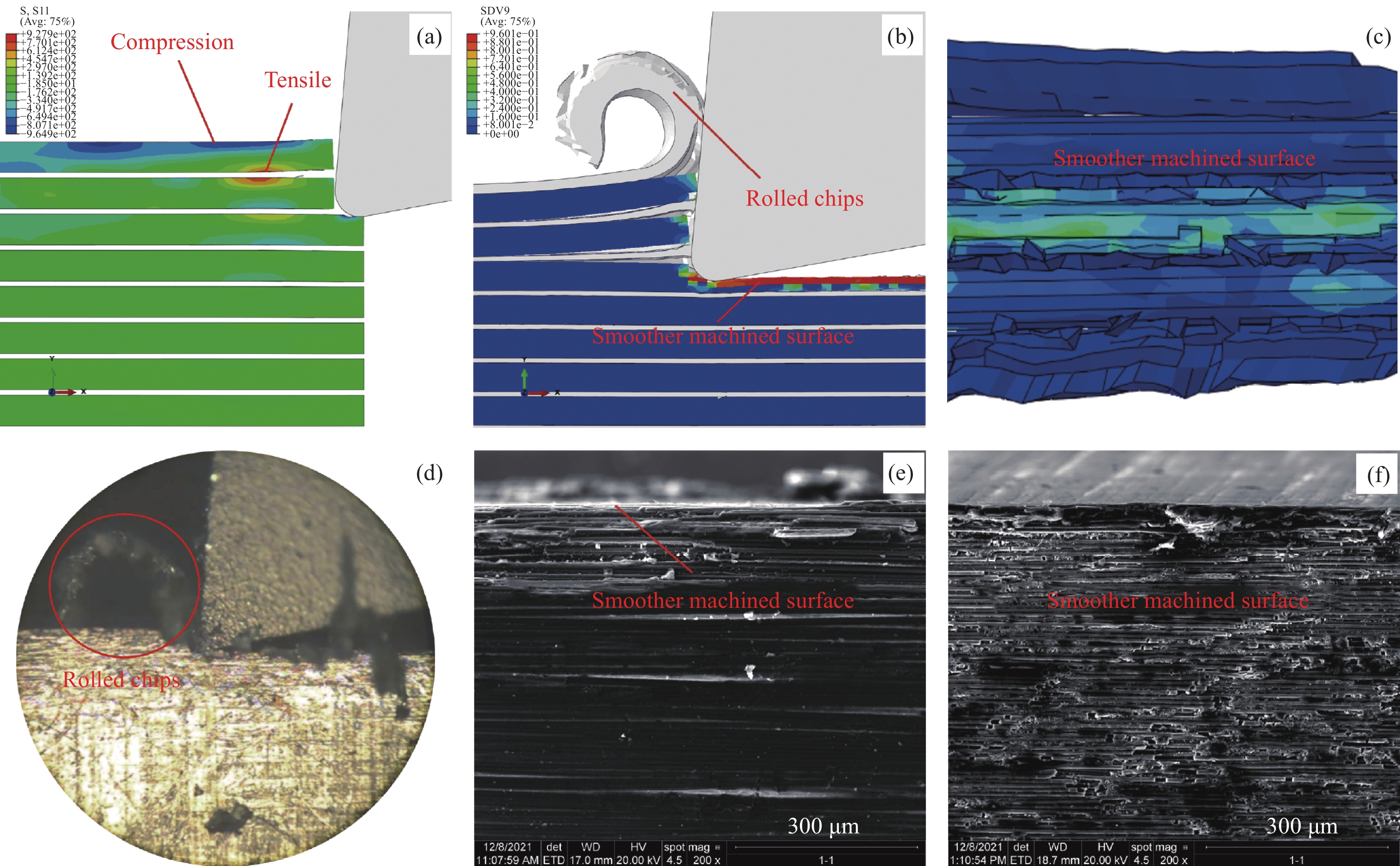
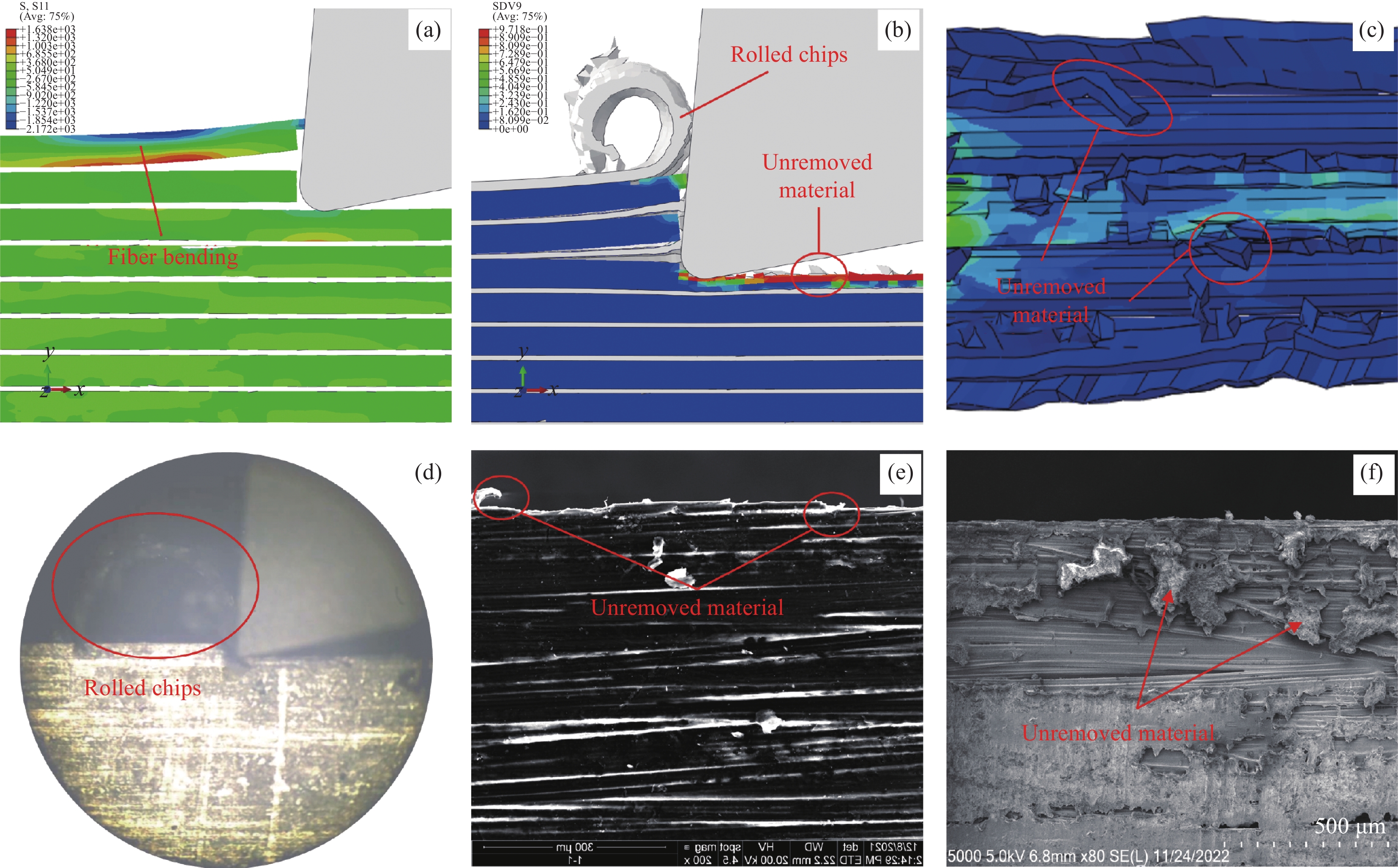
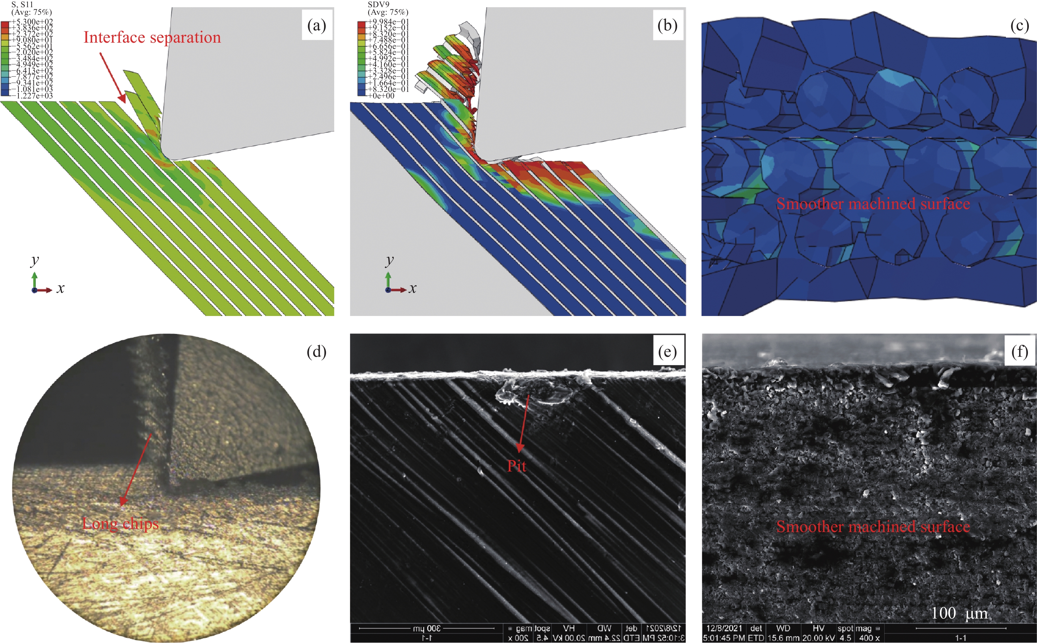
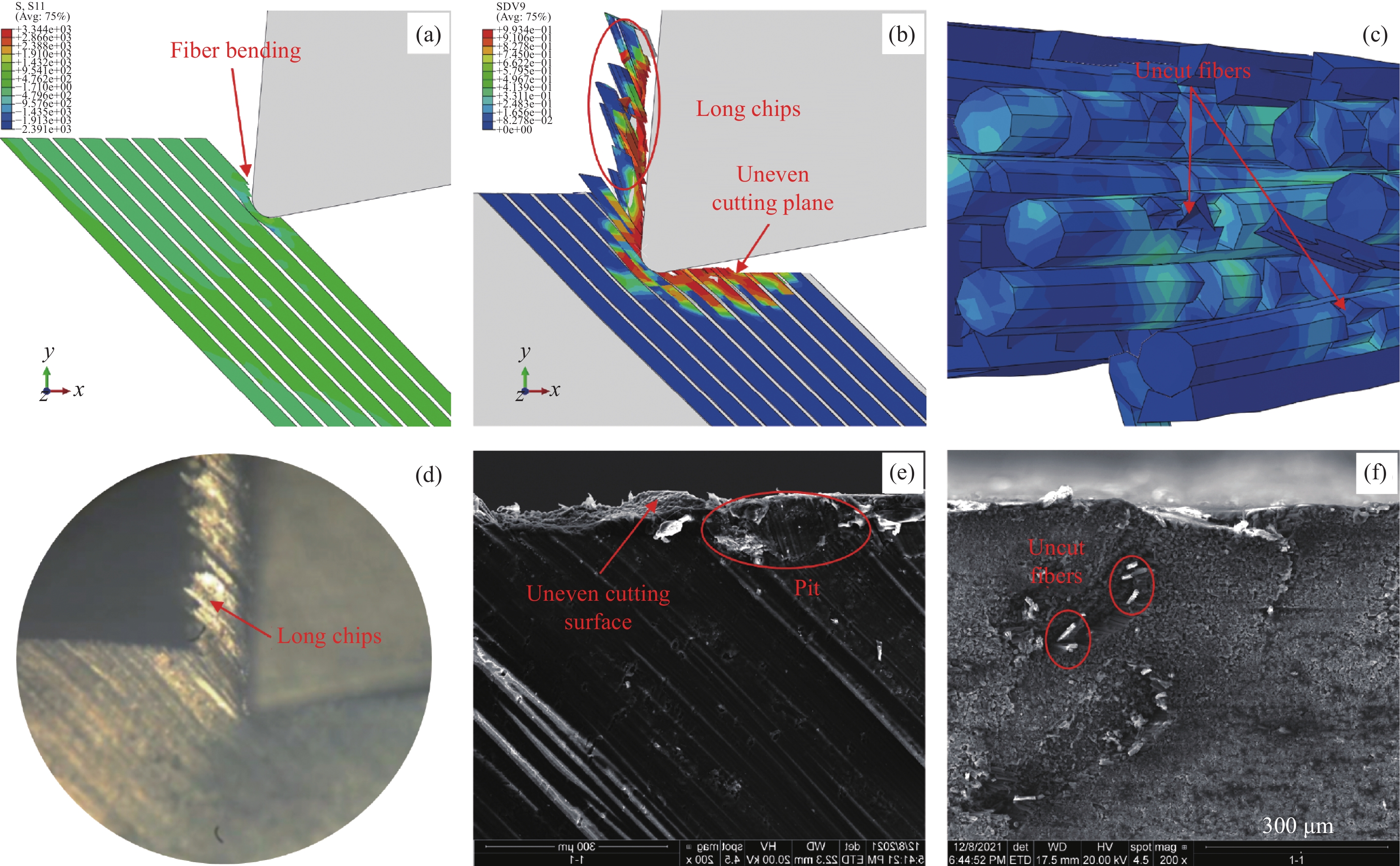
摘要: 碳纤维增强热塑性树脂基复合材料(CFRTP)是高端装备减重增效的优选材料。而CFRTP是一种典型的难加工材料,加工中损伤频发。本文对切削CFRTP时的材料去除及损伤形成过程进行了仿真与实验研究。CFRTP切削时易产生塑性变形,且材料性能受温度影响较大。本文建立CFRTP三维正交切削细观仿真模型,并引入J-C模型表征树脂在不同温度下的弹塑性变形。分析了温度及纤维方向角对CFRTP切削去除过程的影响。结果表明,常温下切削,0°及45°纤维方向角时,已加工面较平整,加工质量较好;90°及135°纤维方向角时,纤维弯曲程度明显增大,已加工面有裂纹产生,加工质量较差。高温下切削,0°纤维方向角时,已加工面出现未去除材料;45°纤维方向角时,已加工面出现裂纹,部分纤维未被切断;90°及135°纤维方向角时,已加工面出现更大开裂,工件出现明显的沿厚度方向上的面外变形,发生面外变形的材料难以被有效去除。Abstract: Carbon fiber reinforced thermoplastic composites (CFRTP) is the preferred material for weight loss and efficiency improvement of high-end equipment. However, CFRTP is a typical difficult-to-machine material, and damage occurs frequently during processing. In this paper, the process of material removal and damage formation during cutting CFRTP was simulated and experimentally studied. CFRTP is prone to plastic deformation during cutting, and the material properties are greatly affected by temperature. In this paper, a three-dimensional orthogonal cutting simulation model of CFRTP was established, and the J-C model was introduced to characterize the elastic-plastic deformation of resin at different temperatures. The effects of temperature and fiber orientation angle on the cutting removal process of CFRTP were analyzed. The results show that when cutting at room temperature, and the fiber orientation angles are 0° and 45°, the machined surface is relatively flat and the processing quality is better; when the fiber orientation angles are 90° and 135°, the bending degree of the fiber increases obviously, and there are cracks on the machined surface, and the processing quality is poor. When cutting at room temperature, and the fiber orientation angle is 0°, the unremoved material appears on the machined surface; when the fiber orientation angle is 45°, cracks and fiber pull-out phenomenon appear on the machined surface. When the fiber orientation angles are 90° and 135°, the machined surface is more cracked, and the workpiece has obvious out-of-plane deformation along the thickness direction. The material with out-of-plane deformation is difficult to be effectively removed.
-
Key words:
- CFRTP /
- temperature /
- orthogonal cutting /
- processing damage /
- simulation
-

图 1 碳纤维增强热塑性树脂基复合材料(CFRTP)仿真模型示意图
Figure 1. Schematic view of carbon fiber reinforced thermoplastic composites (CFRTP) simulation model

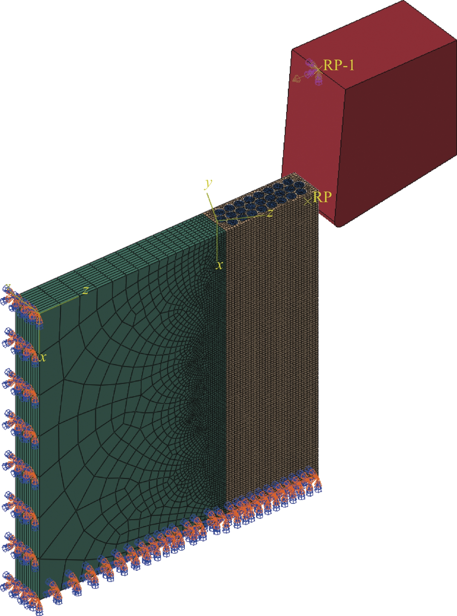
图 2 CFRTP仿真模型的约束及载荷示意图
Figure 2. Constraints and load diagram of CFRTP simulation model
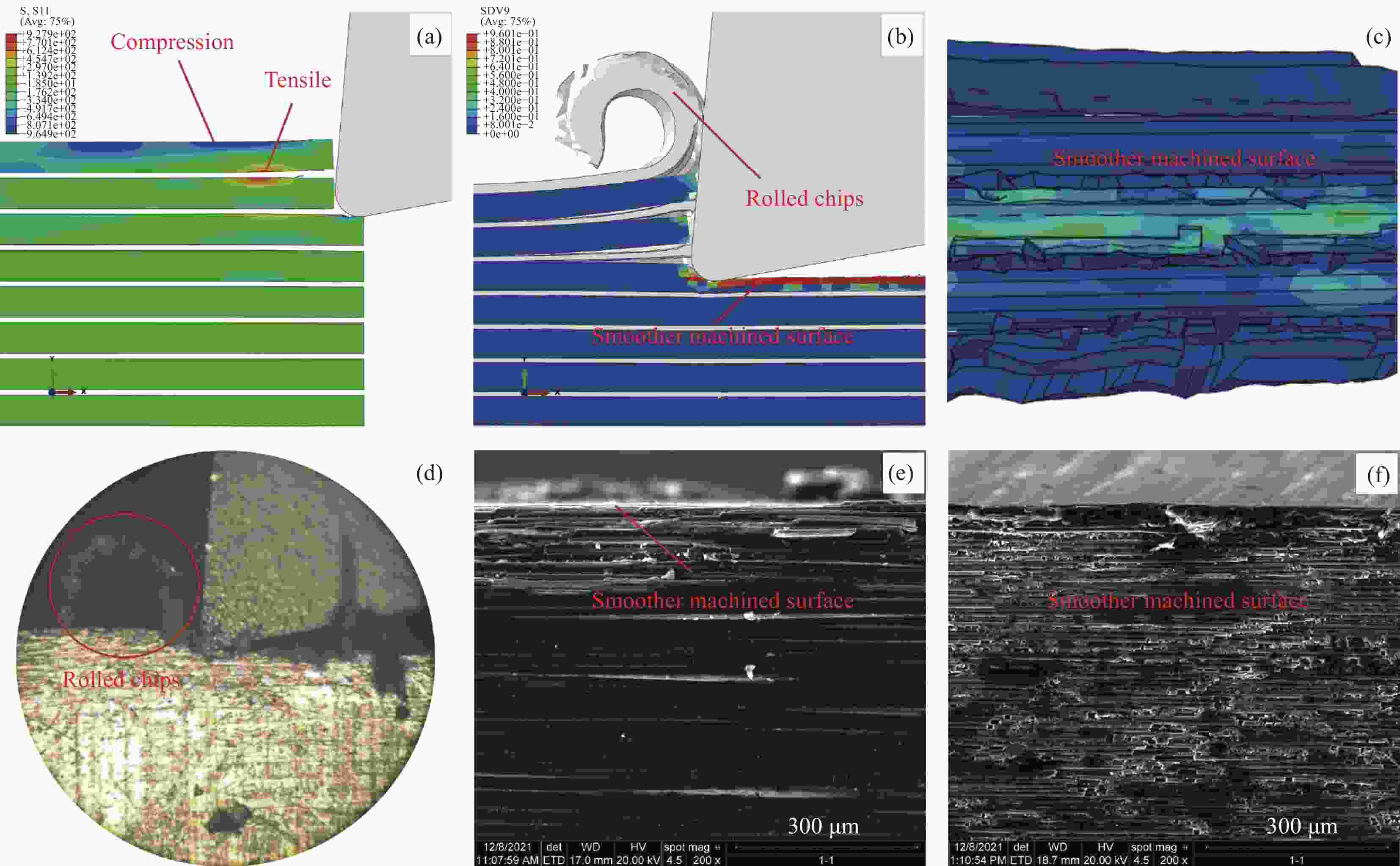
图 6 CFRTP常温下成0°纤维方向角切削
Figure 6. CFRTP is cut into 0 ° fiber direction angle at room temperature
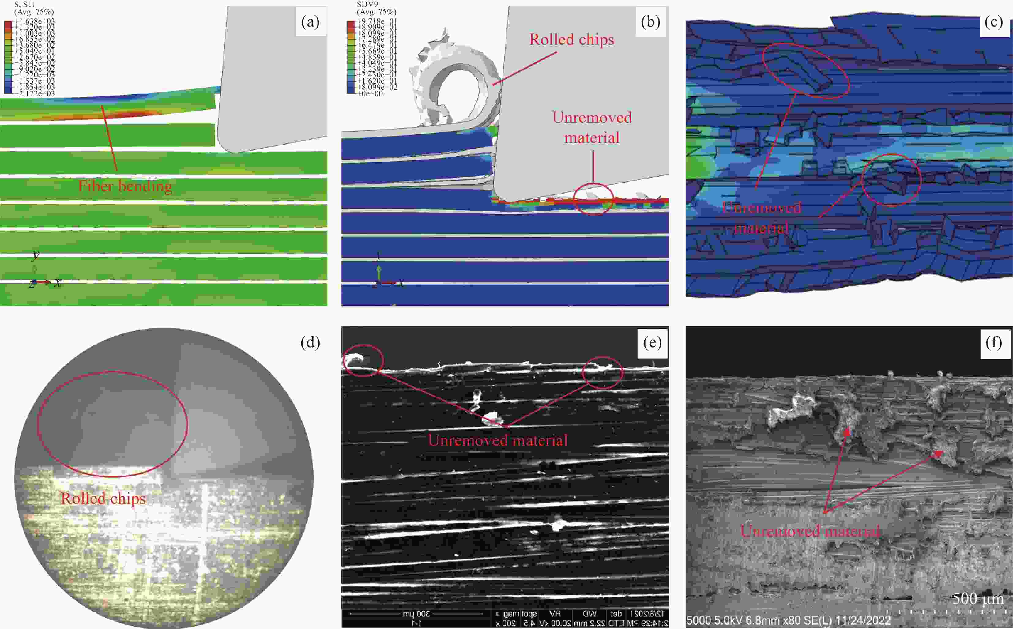
图 7 CFRTP高温下成0°纤维方向角切削
Figure 7. CFRTP is cut into 0 ° fiber direction angle at high temperature

图 8 CFRTP常温下成45°纤维方向角切削
Figure 8. CFRTP is cut into 45 ° fiber direction angle at room temperature

图 9 CFRTP高温下成45°纤维方向角切削
Figure 9. CFRTP is cut into 45 ° fiber direction angle at high temperature

图 10 CFRTP常温下成90°纤维方向角切削
Figure 10. CFRTP is cut into 90 ° fiber direction angle at room temperature
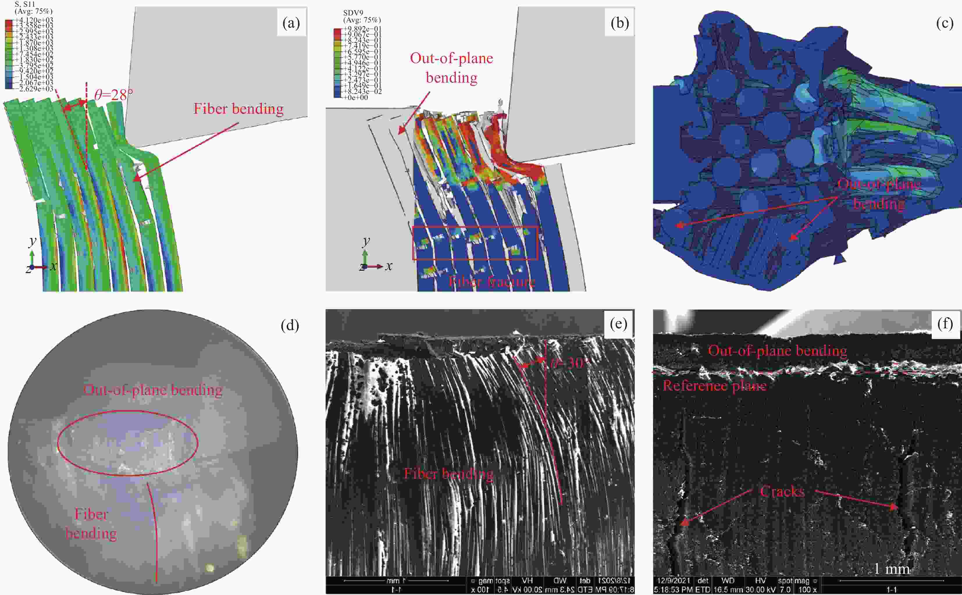
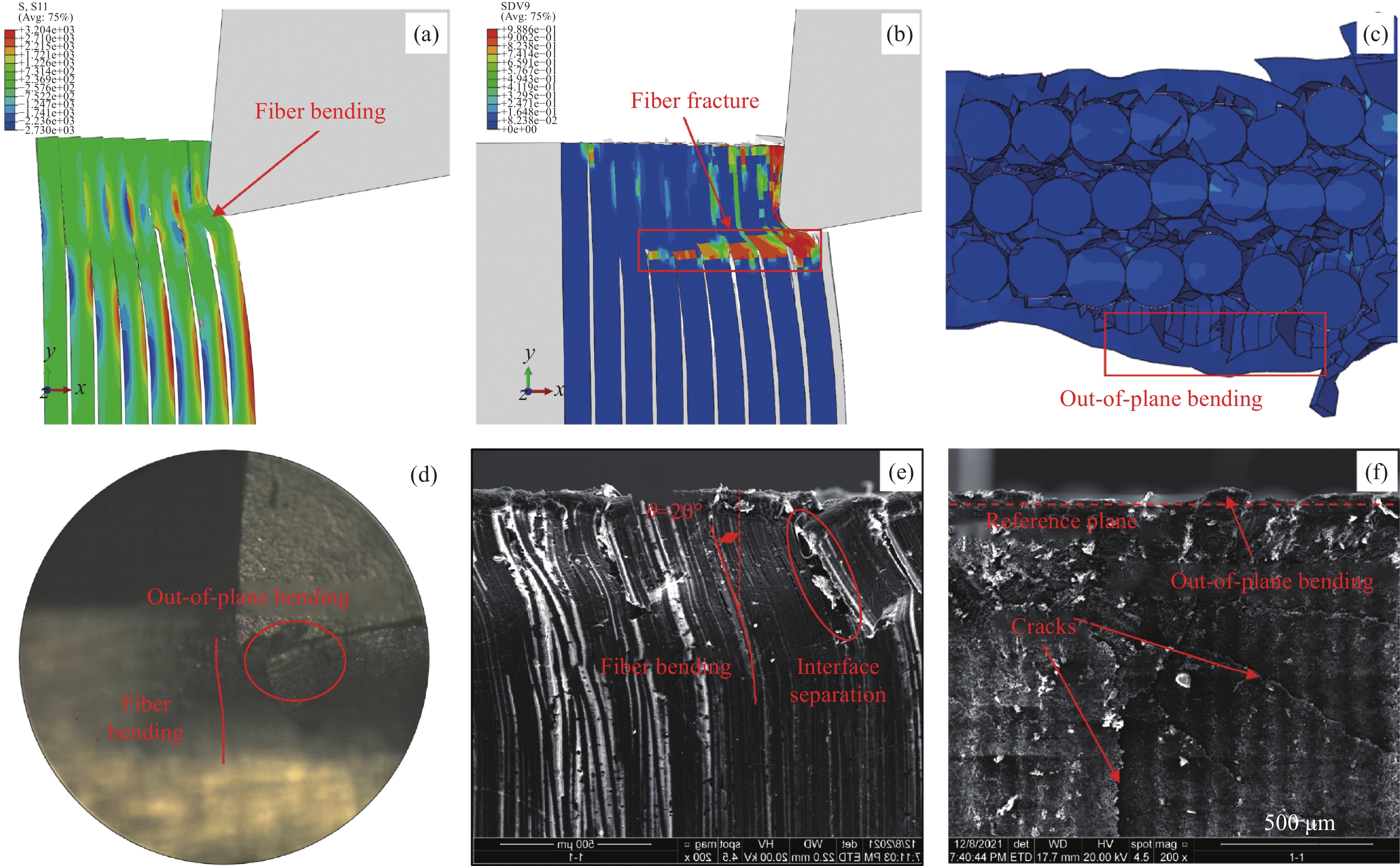
图 11 CFRTP高温下成90°纤维方向角切削
Figure 11. CFRTP is cut into 90 ° fiber direction angle at high temperature

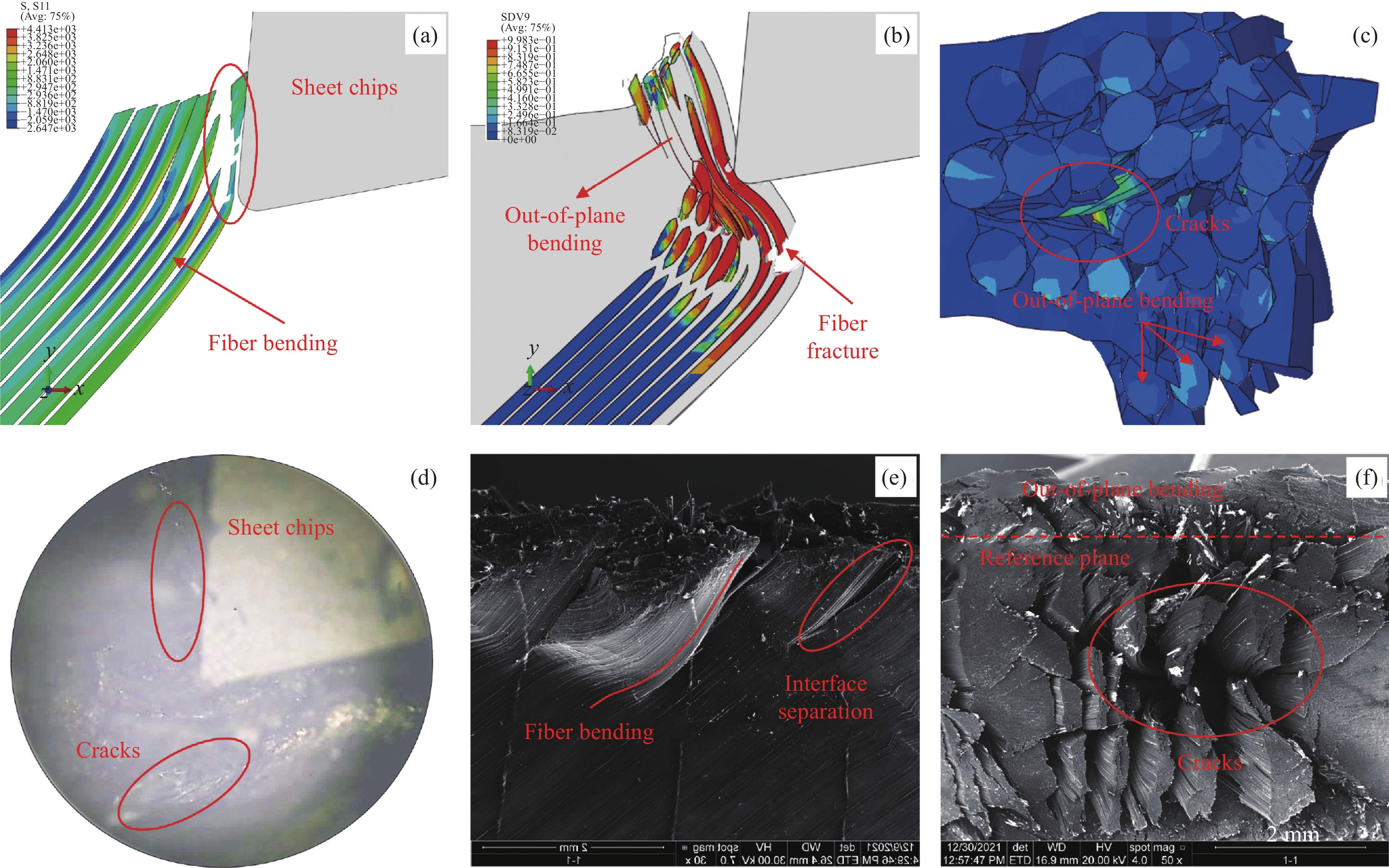
图 12 CFRTP常温下成135°纤维方向角切削
Figure 12. CFRTP is cut into 135 ° fiber direction angle at room temperature

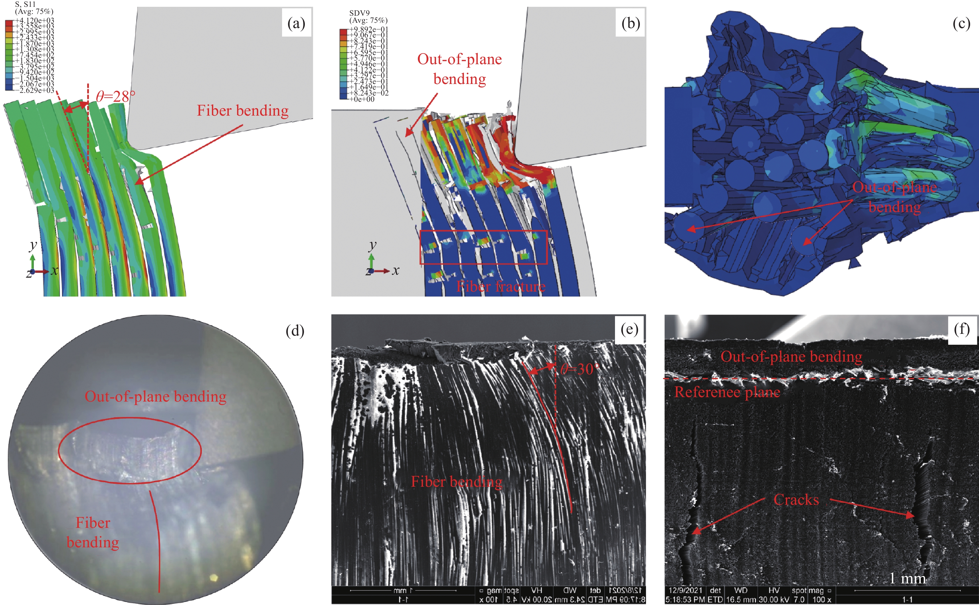
图 13 CFRTP高温下成135°纤维方向角切削
Figure 13. CFRTP is cut into 135 ° fiber direction angle at high temperature
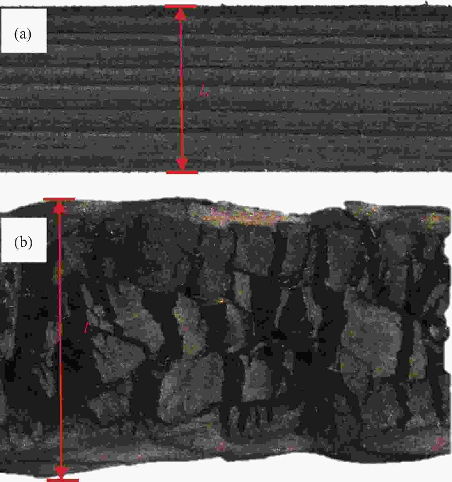
图 14 CFRTP沿厚度方向上的面外变形
Figure 14. The out-of-plane deformation of CFRTP along the thickness direction
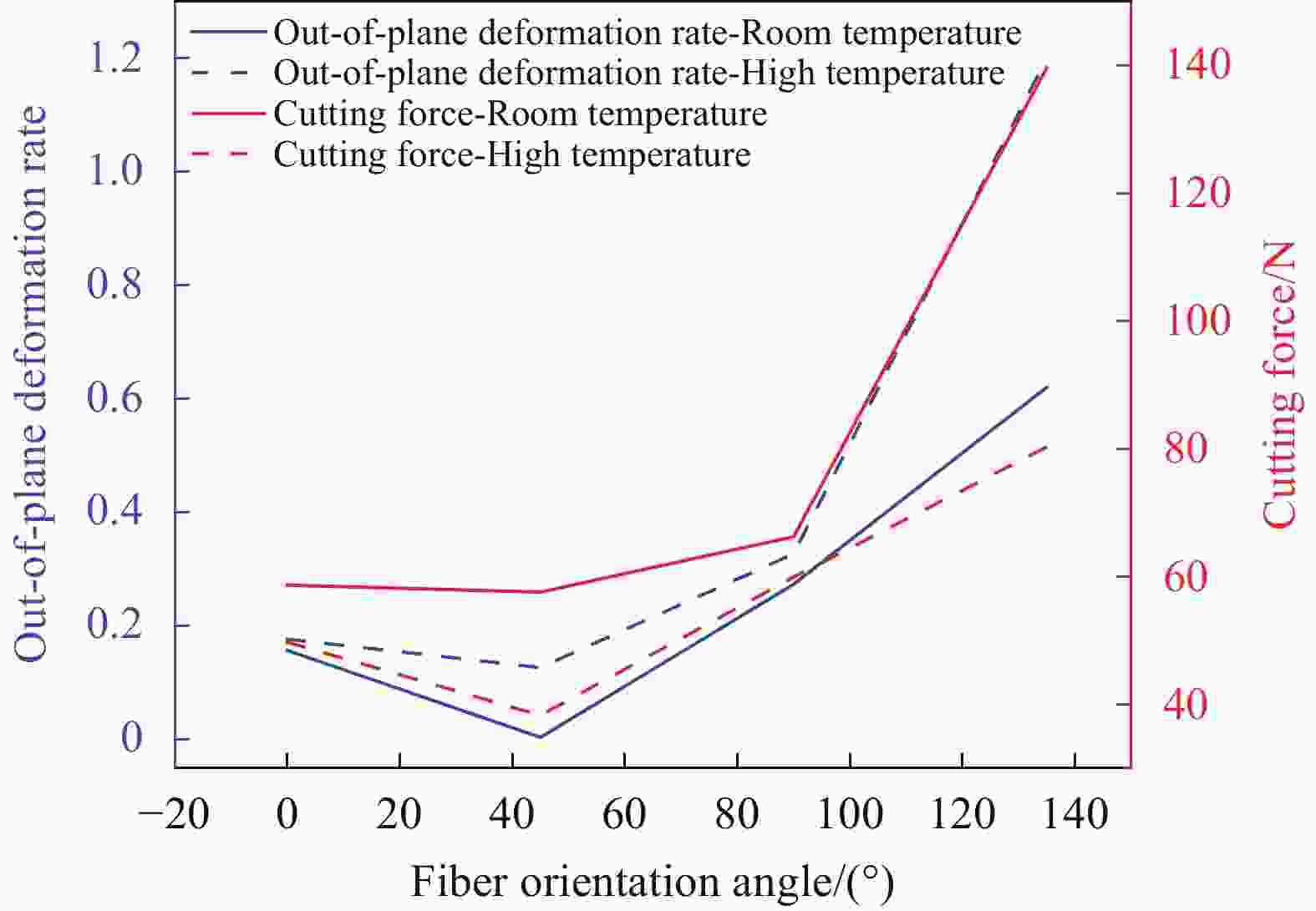
图 15 温度及纤维方向角对CFRTP面外变形的影响
Figure 15. The effects of temperature and fiber orientation angle on the out-of-plane deformation of CFRTP
Material Property Value Carbon fber Elastic constants E11= 294 GPa, E22= E33= 30 GPa, μ11=μ22=μ33= 0.2
G12= G13= 108 GPa, G23= 8.8 GPaLongitudinal strength Xt= 4500 MPa, Xc= 2800 MPa Transverse strength Yt= 200 MPa, Yc= 1000 MPa PEEK Elastic constants E= 4.1 GPa, μ= 0.35 J-C plastic parameter A, B, C, n, m 132 MPa, 10 MPa, 0.034, 1.2, 0.7 J-C failure parameter d1-d5 0.05, 1.2, 0.254, -0.009, 1 Interface Cohesive stiffness k = 6.4 × 10⁵ MPa∕mm Normal and Shear strength $t_{\text{n}}^0 = 43{\text{ }}MP{\text{a, }}t_{\text{s}}^0 = t_{\text{t}}^0 = 50{\text{ }}MP{\text{a}}$ Fracture energy $G_n^C = 1.7{\text{ }}kJ/{{\text{m}}^2}{\text{, }}G_s^C = 2.0{\text{ }}kJ/{{\text{m}}^2}$ B-K exponent η= 1.09 EHM Elastic constants E11= 127 GPa, E22= E33= 10.3 GPa, μ11=μ22=μ33= 0.3
G12= G13= 5.7 GPa, G23= 3.2 GPaNotes:E11, E22 and E33 are the elastic modulus of the material in three directions, respectively; μ11, μ22 and μ33 are Poisson's ratio in three directions of the material, respectively; G12, G13 and G23 are the shear modulus in three directions of the material, respectively; Xt is the tensile strength along the direction of carbon fiber; Xc is the compressive strength along the direction of carbon fiber; Yt is the tensile strength perpendicular to the direction of carbon fiber; Yc is the compressive strength perpendicular to the direction of carbon fiber; E and μ are the elastic modulus and Poisson's ratio of PEEK, respectively; A, B, C, n, m are the plastic parameters of J-C constitutive model; d1-d5 are the parameters of J-C damage model; k is the stiffness of the interface; $ {{t}}_{\text{n}}^{\text{0}} $、$ {{t}}_{\text{s}}^{\text{0}} $ and $ {{t}}_{{t}}^{\text{0}} $ are the strength of the interface in one normal direction and two tangential directions respectively; $ {{G}}_{\text{n}}^{\text{c}} $ and $ {{G}}_{\text{s}}^{\text{c}} $ are the interface normal and tangential fracture energy respectively; η is the interface B-K failure parameter.  下载: 导出CSV
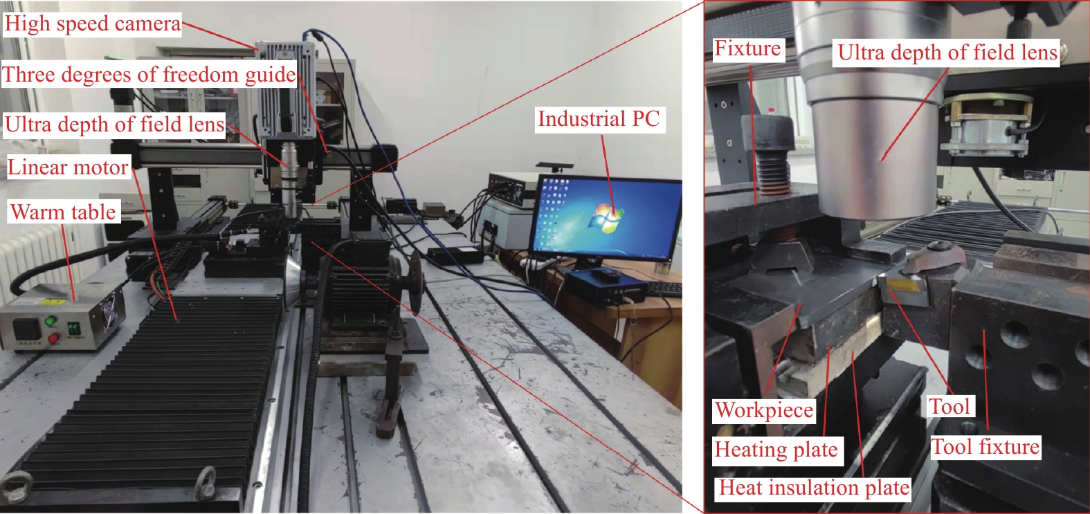
表 2 CFRTP切削实验参数
Table 2. CFRTP cutting experimental parameters
Parameter Value Fiber orientation angle 0°、45°、90°、135° Cutting temperature Room temperature (25℃)
High temperature (200℃)Cutting speed/(mm·s−1) 8.33 Cutting depth/μm 30 Cutting length/mm 55
下载: 导出CSV
-
[1] Noonan M, Obande W, Ray D. Simulated end-of-life reuse of composites from marine applications using thermal reshaping of seawater-aged, glass fibre-reinforced acrylic materials[J]. Composites Part B: Engineering, 2023, 111118. [2] Obande W, Stankovic D, Bajpai A, et al. Thermal reshaping as a route for reuse of end-of-life glass fibre-reinforced acrylic composites[J]. Composites Part B:Engineering, 2023, 257: 110662. doi: 10.1016/j.compositesb.2023.110662 [3] Khan H, Ber R, Neifert S, et al. Carbon fiber-reinforced PEEK spinal implants for primary and metastatic spine tumors: a systematic review on implant complications and radiotherapy benefits[J]. JOURNAL OF NEUROSURGERY-SPINE, 2023, 39(4): 534-547. [4] Zhou X, Dong W, Zhao S, et al. Biomimetic construction of 3D needle-punched CF/PEEK composites based on ladybug forewing structure for directional reinforcement[J]. POLYMER COMPOSITES, 2023, 44(10): 6495-6512. doi: 10.1002/pc.27574 [5] Qiu H, Feng Y, Hong Z, et al. Lightweight multi-layer graded pyramid folded structure based on tucked kirigami for green manufacturing[J]. Composites Science and Technology, 2023, 110383. [6] Siddiqui S, Surananai S, Sainath K, et al. Emerging trends in development and application of 3D printed nanocomposite polymers for sustainable environmental solutions[J]. European Polymer Journal, 2023, 196: 112298. doi: 10.1016/j.eurpolymj.2023.112298 [7] Ge J, Zhang W, Luo M, et al. Multi-objective optimization of thermoplastic CF/PEKK drilling through a hybrid method: An approach towards sustainable manufacturing[J]. Composites Part A:Applied Science and Manufacturing, 2023, 167: 107418. doi: 10.1016/j.compositesa.2022.107418 [8] Dai G, Zhan L, Ma B, et al. Effect of process parameters on interlaminar properties of thermoplastic composite: Molecular dynamics simulation and experimental verification[J]. POLYMER, 2023, 280. [9] Pang X, Yue S, Huang S, Xie J, et al. Effects of ambient humidity and sintering temperature on the tribological and antistatic properties of PEEK and CF/PEEK[J]. FRONTIERS IN MATERIALS, 2023, 10. [10] Ramaswamy K, Modi V, Rao P, et al. An investigation of the influence of matrix properties and fibre-matrix interface behaviour on the mechanical performance of carbon fibre-reinforced PEKK and PEEK composites[J]. COMPOSITES PART A-APPLIED SCIENCE AND MANUFACTURING, 2023, 165. [11] Ge J, Catalanotti G, Falzon B, et al. Towards understanding the hole making performance and chip formation mechanism of thermoplastic carbon fibre/polyetherketoneketone composite[J]. Composites Part B:Engineering, 2022, 234: 109752. doi: 10.1016/j.compositesb.2022.109752 [12] Du Y, Yang T, Liu C. Comparative study on machining performance of conventional and ultrasonic-assisted drilling of carbon fiber-reinforced polyetheretherketone composite[J]. JOURNAL OF THE BRAZILIAN SOCIETY OF MECHANICAL SCIENCES AND ENGINEERING, 2023, 45 (10). [13] Liu S, Sun Y, Du Y, et al. Investigating the material removal mechanism and cutting performance in ultrasonic vibration-assisted milling of carbon fibre reinforced thermoplastic[J]. MATERIALS RESEARCH EXPRESS, 2023, 10 (9). [14] Hou G, Luo B, Zhang K, et al. Investigation of high temperature effect on CFRP cutting mechanism based on a temperature controlled orthogonal cutting experiment[J]. Composite Structures, 2021, 268: 113967. doi: 10.1016/j.compstruct.2021.113967 [15] Han L, Zhang J, Liu Y, et al. Finite element investigation on pretreatment temperature-dependent orthogonal cutting of unidirectional CFRP[J]. COMPOSITE STRUCTURES, 2021, 278. [16] Li S, Cao Z, Chen R, et al. Strengthening the bonding interfaces of hybrid titanium carbon laminates by bionic micro texture and carbon nanotube pinning[J]. Composites Science and Technology, 2023, 232: 109865. doi: 10.1016/j.compscitech.2022.109865 [17] Li S, Dai L, Li C, et al. Prediction model of chisel edge thrust force and material damage mechanism for interlaminar-direction drilling of UD-CFRP composite laminates[J]. Composite Structures, 2022, 298: 116023. doi: 10.1016/j.compstruct.2022.116023 [18] Li S, Teng H, Dai L, et al. Comprehensive prediction model of drilling temperature of UD-CFRP laminates considering the combined action of main cutting edge and chisel edge[J]. Composite Structures, 2023, 313: 116899. doi: 10.1016/j.compstruct.2023.116899 [19] Song Y, Cao H, Qu D, et al. Impact effect-based dynamics force prediction model of high-speed dry milling UD-CFRP considering size effect[J]. International Journal of Impact Engineering, 2023, 179: 104659. doi: 10.1016/j.ijimpeng.2023.104659 [20] Song Y, Qu D, Wu B, et al. Composite light ropes model-based dynamics force prediction model of high speed dry milling UD-CF/PEEK considering size effect[J]. Journal of Manufacturing Processes, 2022, 76: 210-222. doi: 10.1016/j.jmapro.2022.01.069 [21] Ge J, Tan W, Ahmad S, et al. Temperature-dependent cutting physics in orthogonal cutting of carbon fibre reinforced thermoplastic (CFRTP) composite[J]. Composites Part A:Applied Science and Manufacturing, 2024, 176: 107820. doi: 10.1016/j.compositesa.2023.107820 [22] Qin X, Wu X, Li H, et al. Numerical and experimental investigation of orthogonal cutting of carbon fiber-reinforced polyetheretherketone (CF/PEEK)[J]. The International Journal of Advanced Manufacturing Technology, 2022, (1/2): 119. [23] Tan W, Falzon B, Price M, Predicting the crushing behaviour of composite material using high-fidelity finite element modelling[J]. International Journal of Crashworthiness, 2014, 20 (1), 60-77. [24] Zhang B, Wang F, Wang Q, et al. Novel fiber fracture criteria for revealing forming mechanisms of burrs and cracking at hole-exit in drilling Carbon Fiber Reinforced Plastic[J]. Journal of Materials Processing Technology, 2021, 289: 116934. doi: 10.1016/j.jmatprotec.2020.116934 [25] Wang F, Wang X, Jin X, et al. A comparison of cutting mechanisms of the carbon fibre reinforced thermoset and thermoplastic composites by the experimental and computational modelling methods[J]. Journal of Manufacturing Processes, 2022, 79: 895-910. doi: 10.1016/j.jmapro.2022.05.033 [26] Garcia D, Rodriguez M, Rusinek A, et al. Low temperature effect on impact energy absorption capability of PEEK composites[J]. COMPOSITE STRUCTURES, 2015, 134: 440-449. doi: 10.1016/j.compstruct.2015.08.090 [27] Chen F, Ou H, Lu B, et al. A constitutive model of polyether-ether-ketone (PEEK)[J]. Journal of the Mechanical Behavior of Biomedical Materials, 2016, 53: 427-433. doi: 10.1016/j.jmbbm.2015.08.037 [28] Chang B, Wang X, Long Z, et al. Constitutive modeling for the accurate characterization of the tension behavior of PEEK under small strain[J]. Polymer Testing, 2018, 69: 514-521. doi: 10.1016/j.polymertesting.2018.06.003 [29] Garcia D, Rusinek A, Jankowiak T, et al. Mechanical impact behavior of polyether–ether–ketone (PEEK)[J]. Composite Structures, 2015, 124: 88-99. doi: 10.1016/j.compstruct.2014.12.061 [30] Liu H, Liu J, Ding Y, et al. A three-dimensional elastic-plastic damage model for predicting the impact behaviour of fibre-reinforced polymer-matrix composites[J]. Composites Part B:Engineering, 2020, 201: 108389. doi: 10.1016/j.compositesb.2020.108389 [31] Liu H, Liu J, Ding Y, et al. The behaviour of thermoplastic and thermoset carbon-fibre composites subjected to low-velocity and high-velocity impact[J]. Journal of Materials Science, 2020, 55 (33). [32] Xu X, Jin X, 3-D finite element modeling of sequential oblique cutting of unidirectional carbon fiber reinforced polymer[J]. Composite Structures, 2021, 256, 113127. -


 下载:
下载:


 点击查看大图
计量
- 文章访问数: 58
- HTML全文浏览量: 24
- 被引次数: 0
