


Calculation of the heat distribution ratio of tool-chip-workpiece and prediction of cutting temperature during the peripheral milling process of carbon fiber reinforced thermoplastic resin matrix composites
-
摘要: 碳纤维增强热塑性树脂基复合材料(简称“热塑性复材”)对温度变化敏感。针对碳纤维/聚醚醚酮(CF/PEEK)热塑性复材周铣加工过程,建立了包括各向异性材料塑性变形与刀-工-屑多面摩擦作用的复合热源模型,求解了以不同纤维方向切削热塑性复材时刀-工-屑的切削热量分配比例,最终构建了热塑性复材周铣温度预测模型,并由此分析了纤维方向、切削速度、进给量等工艺参数的影响。经实验验证,模型平均预测误差低于11.5%。结果表明:大角度切削时,流入工件的热量比例更高,导致铣削温度更高。随切削速度的增大,铣削温度先上升后下降,切削速度临界值在100 m/min附近;而随着进给量增加,铣削温度总体呈下降趋势,当进给量由0.01 mm/r增大到0.1 mm/r时,铣削温度下降40%以上。Abstract: Carbon fiber reinforced thermoplastic resin matrix composites (CFRTP) are sensitive to temperature change. A composite heat source model for the peripheral milling process of carbon fiber (CF)/poly(ether-ether-ketone) (PEEK) thermoplastic composites was established, which included the plastic deformation of anisotropic materials and the multi-faceted friction from tool-workpiece and tool-chip. The cutting heat distribution ratio of tool-chip-workpiece was solved when cutting thermoplastic composites in different fiber orientations. Finally, a prediction model for the peripheral milling temperature of thermoplastic composite materials was constructed, and the effects of process parameters such as fiber orientations, cutting speed and feed rate were analyzed. Through experimental verification, the average prediction error of the model is less than 11.5%. The results show that a higher proportion of heat flows into the workpiece when performing machining with a large cutting angle, resulting in higher milling temperatures. With the increase of cutting speed, the milling temperature first increases and then decreases, and the critical value is around 100 m/min. As the feed rate increases, the overall milling temperature shows a downward trend. When the feed rate increases from 0.01 to 0.1 mm/r, the milling temperature decreases by more than 40%.
-
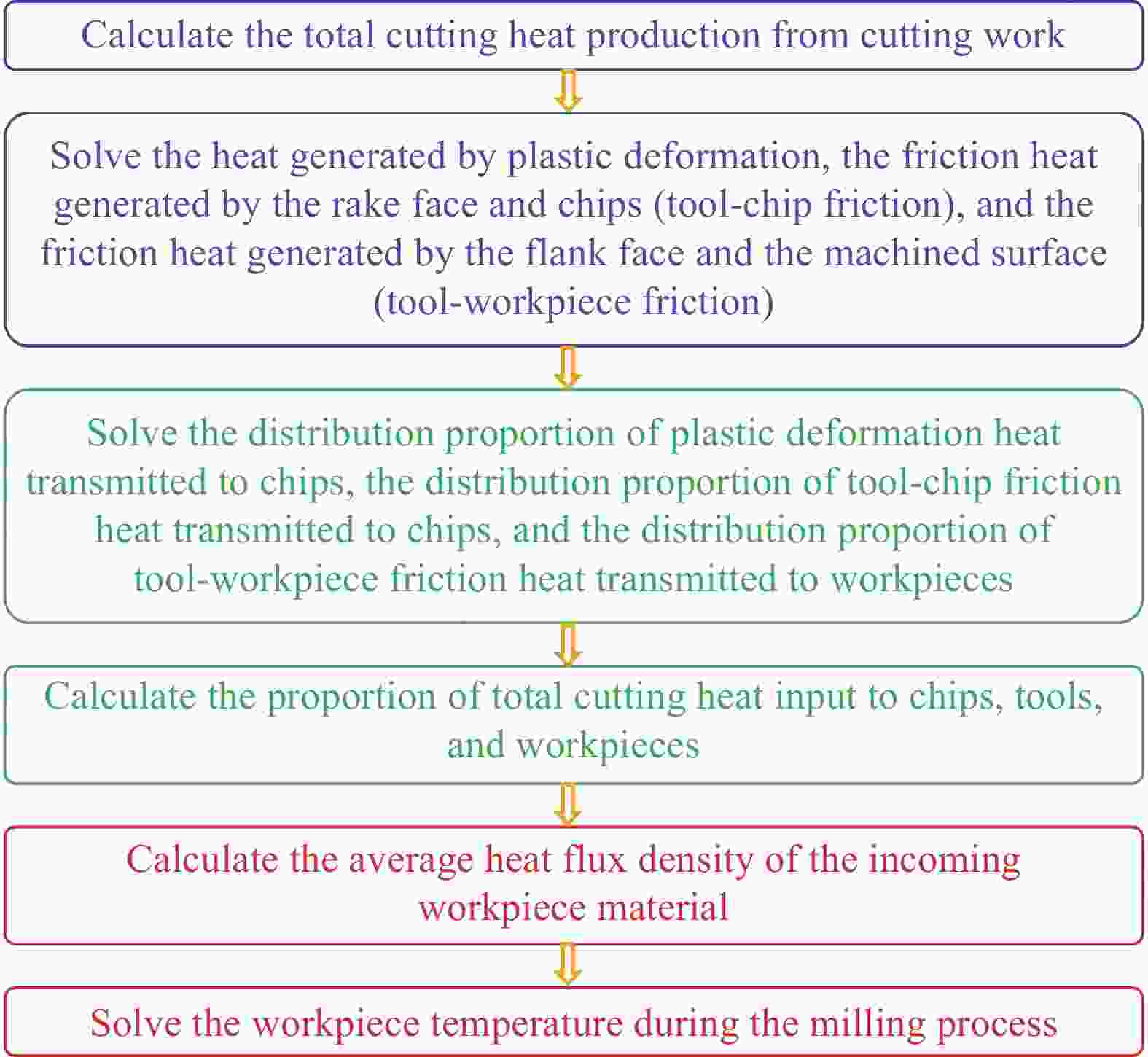
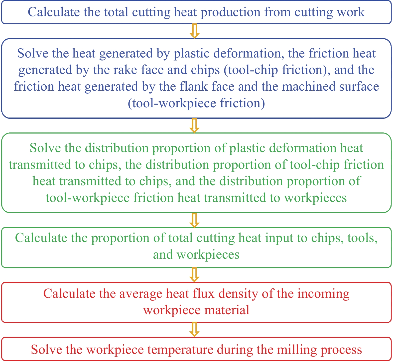
图 1 碳纤维增强热塑性树脂基复合材料(CFRTP)周铣温度计算流程示意图
Figure 1. Schematic diagram of carbonfiber reinforced thermoplastic resin matrix composites (CFRTP) milling temperature calculation process
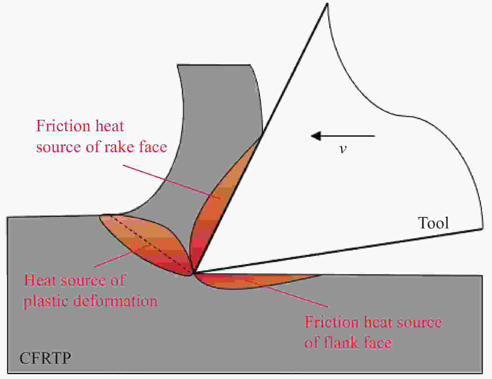
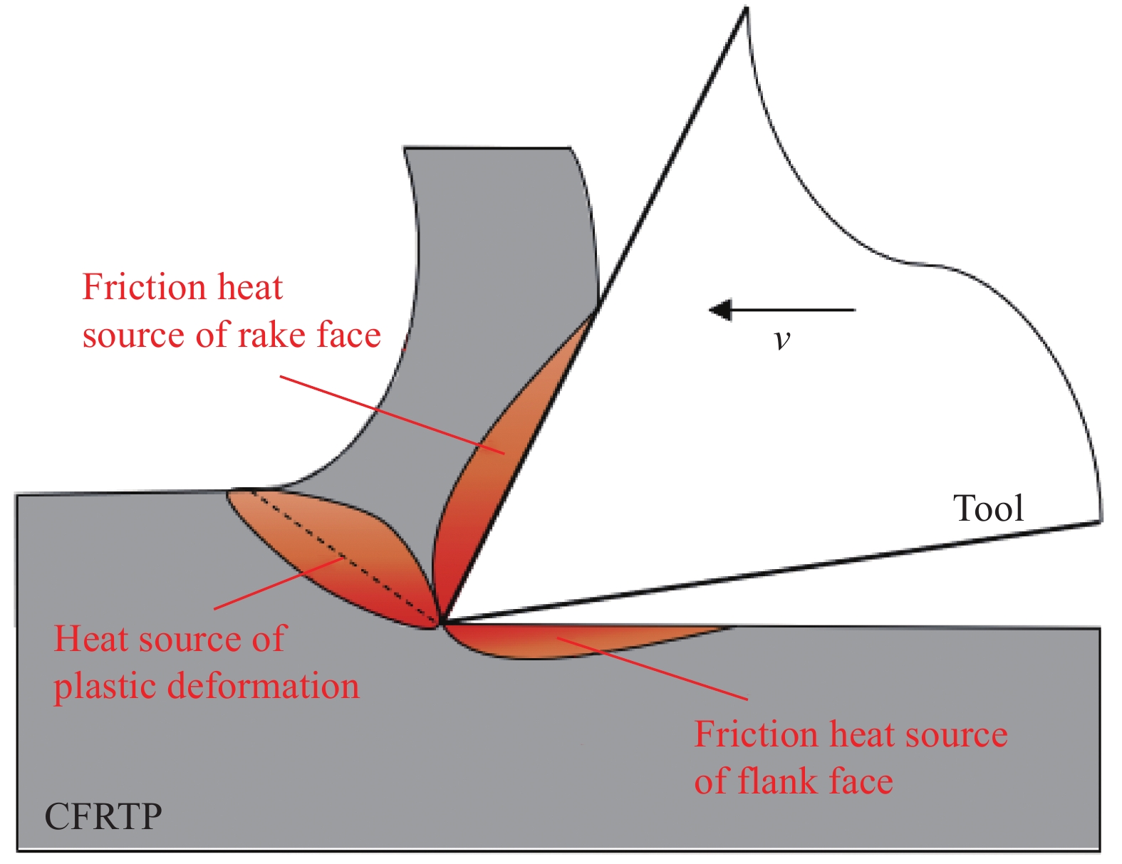
图 2 CFRTP加工时产热示意图
Figure 2. Schematic diagram of heat source during CFRTP processing
v—Cutting speed (feed speed)
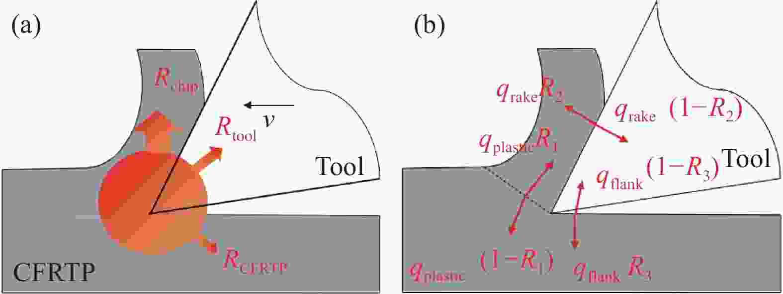
图 3 CFRTP加工时传热机制示意图
Figure 3. Schematic diagram of heat transfer mechanism during CFRTP processing
qrake—Heat flux density of friction heat source on rake face; qplastic—Heat flux density of plastic deformation heat source; qflank—Heat flux density of friction heat source on flank face; R1—Distribution ratio of plastic deformation heat transmitted to chip; R2—Proportion of heat generated by friction between the tool and the chips transmitted to chip distribution; R3—Proportion of heat generated by friction between the tool and the workpiece transmitted to the workpiece distribution; Rchip—Heat distribution ratio of incoming chips; Rtool—Heat distribution ratio of incoming the tool; RCFRTP—Heat distribution ratio of incoming the workpiece

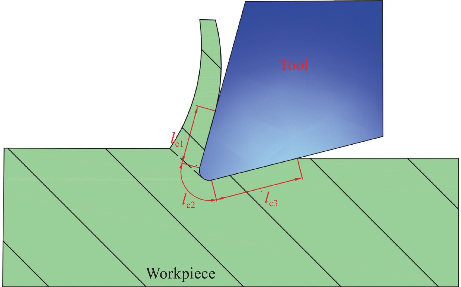
图 5 刀具与工件接触长度示意图
Figure 5. Schematic diagram of contact length between cutting tool and workpiece
lc1—Contact length between chips and rake face; lc2—Contact length between the corner and the workpiece; lc3—Contact length between flank face and machined surface
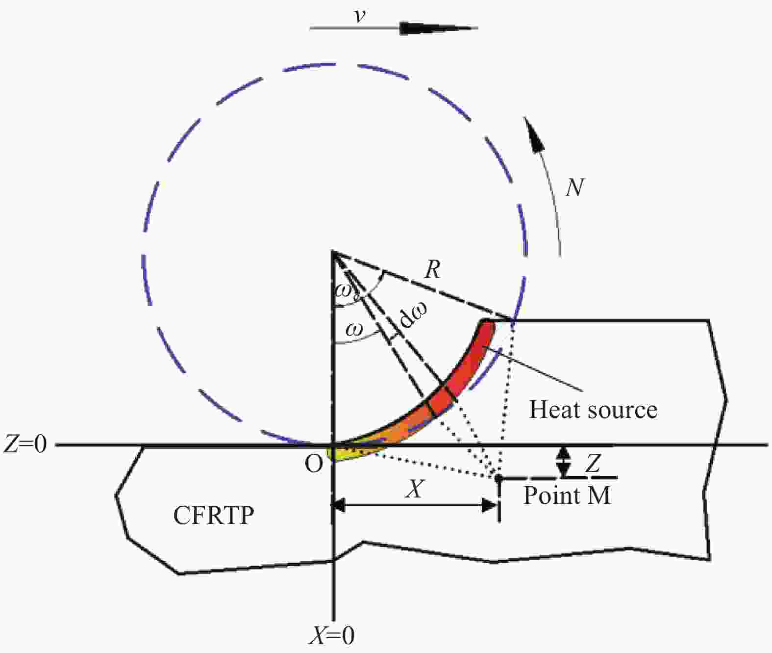
图 6 CFRTP周铣传热示意图
Figure 6. Heat transfer diagram of CFRTP peripheral milling
N—Tool speed; ωc—Angle of the tool turning when cutting the workpiece; ω—Angle of a point in the workpiece relative to the origin of the coordinate; dω—Small increment of tool turning angle; X, Z—Distance from a point on the workpiece to the two axes respectively; R—Radius of milling cutter

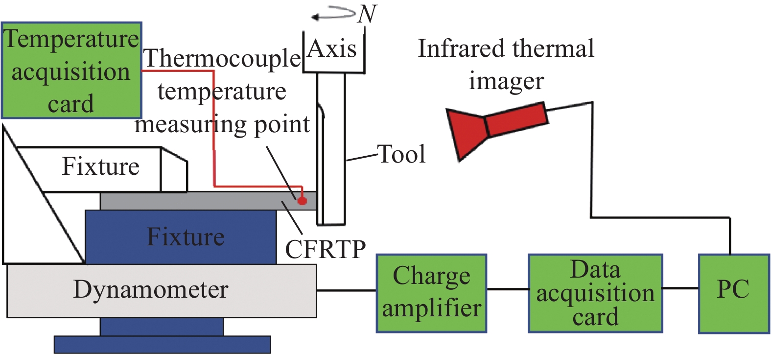
图 7 CFRTP铣削实验示意图
Figure 7. Schematic diagram of CFRTP milling experiment
PC—Industrial personal computer
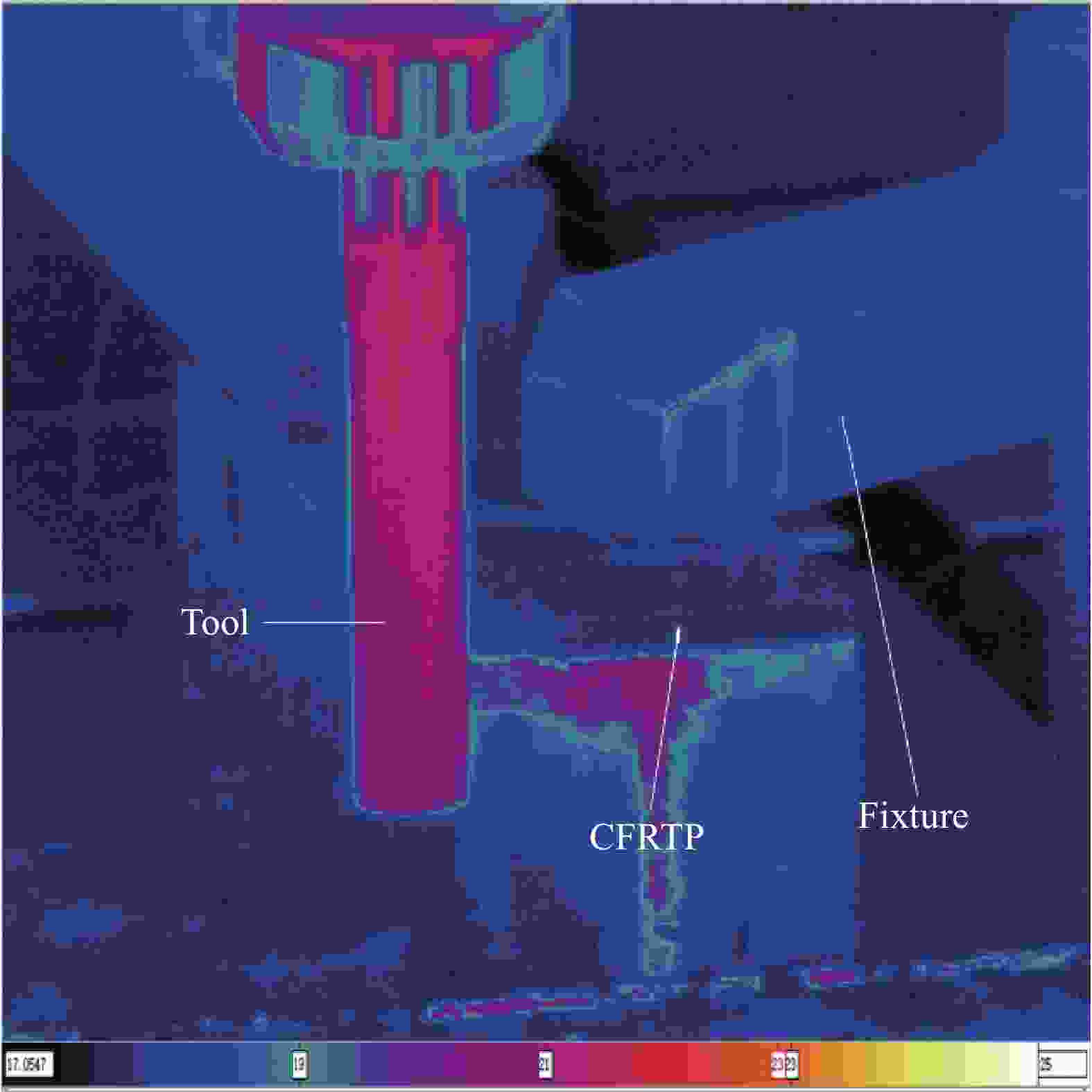
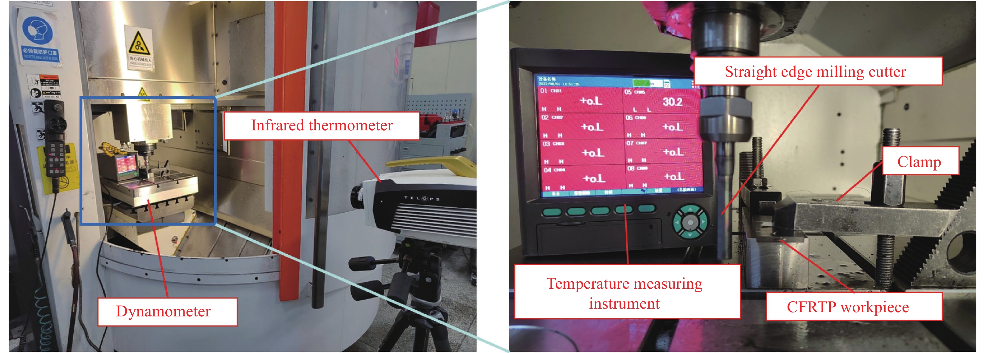
图 11 红外成像仪下周铣装置示意图
Figure 11. Schematic diagram of infrared imager peripheral milling device
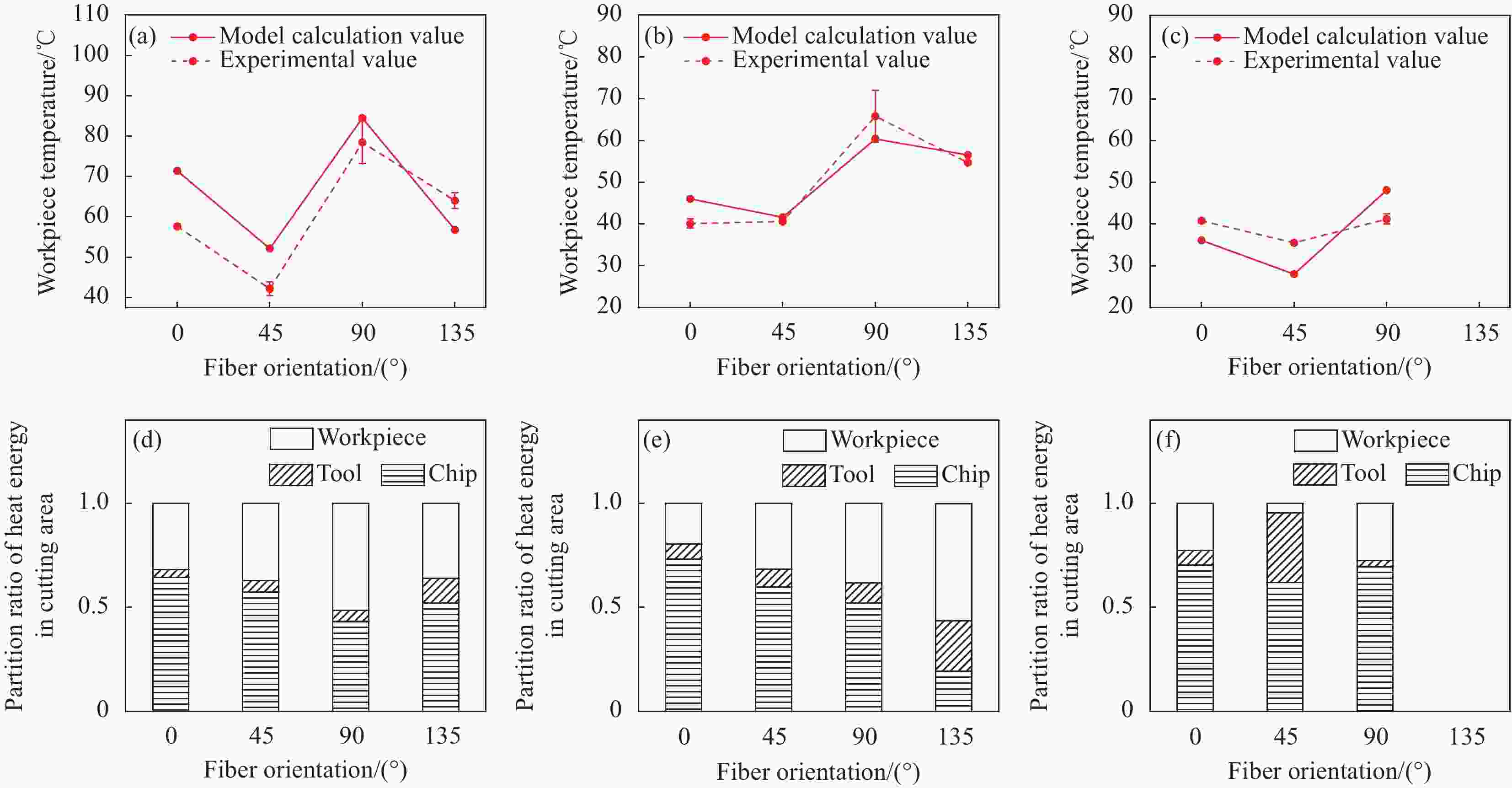
图 12 纤维方向角对工件温度((a)~(c))和热分配比例系数((d)~(f))的影响:((a), (d)) v=100 m/min,fz=0.05 mm/r;((b), (e)) v=200 m/min,fz=0.05 mm/r;((c), (f)) v=100 m/min,fz=0.1 mm/r
Figure 12. Influence of fiber orientation angle on workpiece temperature ((a)-(c)) and heat partition ratio coefficient ((d)-(f)): ((a), (d)) v=100 m/min, fz=0.05 mm/r; ((b), (e)) v=200 m/min, fz=0.05 mm/r; ((c), (f)) v=100 m/min, fz=0.1 mm/r
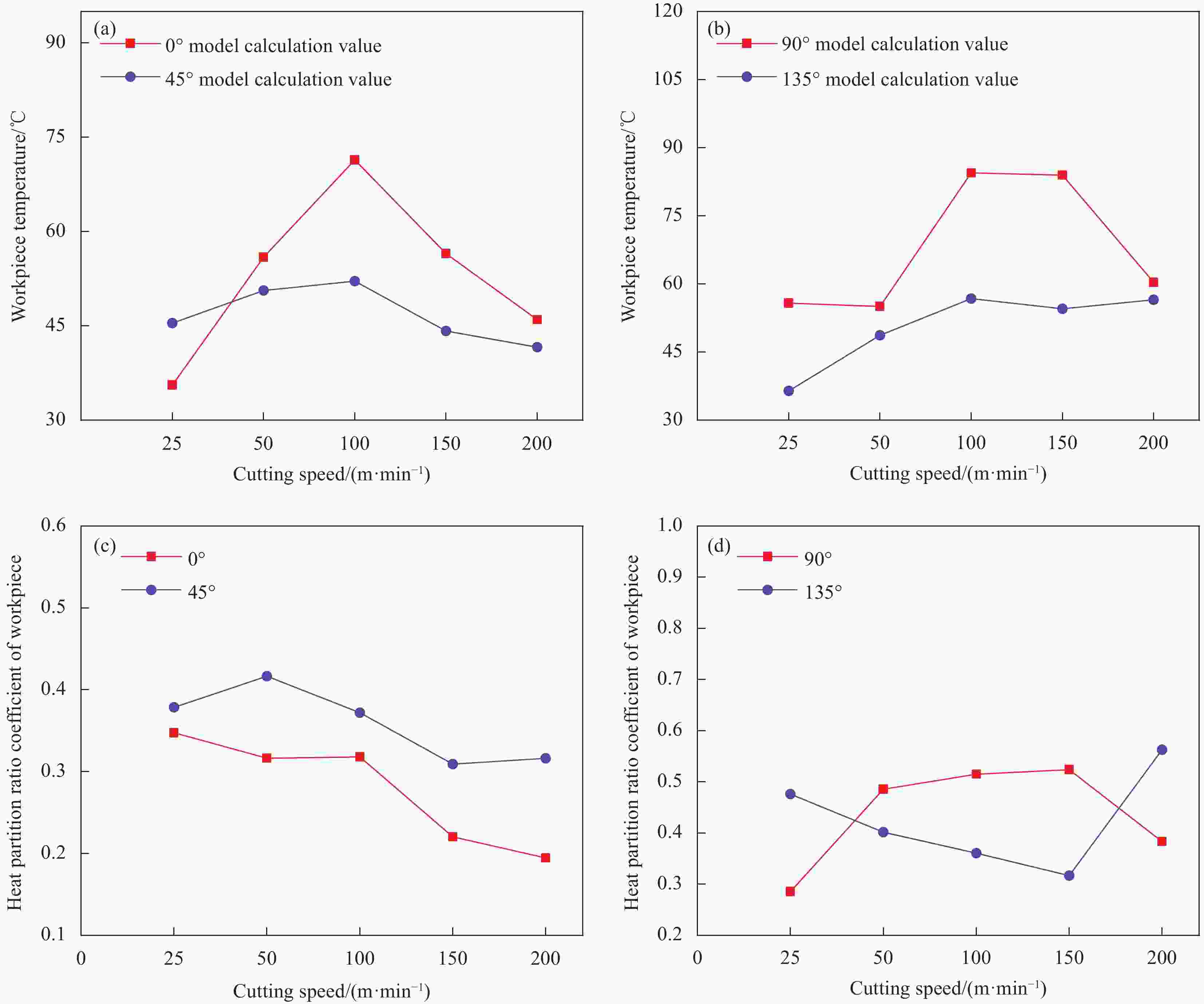
图 13 切削速度对工件温度((a), (b))和热分配比例系数((c), (d))的影响(fz=0.05 mm/r)
Figure 13. Influence of cutting speed on temperature ((a), (b)) and heat partition ratio coefficient ((c), (d)) of workpiece (fz=0.05 mm/r)

图 14 进给量对工件温度的影响:(a) 0°;(b) 90°
Figure 14. Influence of feed rate on temperature of workpiece: (a) 0°; (b) 90°
表 1 CFRTP材料属性
Table 1. Properties of CFRTP
Parameter Value Longitudinal tensile strength/MPa 2070 Transverse compressive strength/MPa 102 Longitudinal Young's modulus/GPa 127 Transverse Young's modulus/GPa 10.3 Poisson's ratio 0.3 Glass transition temperature of resin Tg/℃ 143  下载: 导出CSV
表 2 刀具参数和加工参数
Table 2. Tool parameters and machining parameters
Parameter Value Tool diameter D/mm 10 Main cutting edge rake angle γ0/(°) 5 Main cutting edge clearance angle α/(°)
Number of main cutting edges
Coating3
2
Black nanometerCutting speed v/(m·min−1) 25, 50, 100, 150, 200 Feed per revolution fz/(mm·r−1) 0.01, 0.025, 0.05, 0.075, 0.1 Radial cutting depth a'c/mm
Milling mode0.3
Climb milling
下载: 导出CSV
-
[1] 杜善义. 先进复合材料与航空航天[J]. 复合材料学报, 2007, 24(1):1-12. doi: 10.3321/j.issn:1000-3851.2007.01.001(inChinese)DU Shanyi. Advanced composite materials and aerospace engineering[J]. Acta Materiae Compositae Sinica,2007, 24(1):1-12(in Chinese). doi: 10.3321/j.issn:1000-3851.2007.01.001(inChinese) [2] LIM S J, CHEON J, KIM M. Effect of laser surface treatments on a thermoplastic PA6/carbon composite to enhance the bonding strength[J]. Composites Part A: Applied Science and Manufacturing,2020,137:105989. doi: 10.1016/j.compositesa.2020.105989 [3] STEWART R. Thermoplastic composites—Recyclable and fast to process[J]. Reinforced Plastics,2011,55(3):22-28. doi: 10.1016/S0034-3617(11)70073-X [4] GE J, CATALANOTTI G, FALZON B G, et al. Towards understanding the hole making performance and chip formation mechanism of thermoplastic carbon fibre/polyetherketoneketone composite[J]. Composites Part B: Engineering,2022,234:109752. doi: 10.1016/j.compositesb.2022.109752 [5] YAMAMOTO T, TERADA Y. Use of hollow colloids for generating nanovoids to mitigate the brittle fracture of carbon fiber-reinforced thermoplastics[J]. Composites Part A: Applied Science and Manufacturing,2021,149:106506. doi: 10.1016/j.compositesa.2021.106506 [6] LEE J M, LEE C J, KIM B M, et al. Design of prepreg compression molding for manufacturing of CFRTP B-pillar reinforcement with equivalent mechanical properties to existing steel part[J]. International Journal of Precision Engineering and Manufacturing,2020,21(3):545-556. doi: 10.1007/s12541-019-00265-z [7] YAO S S, JIN F L, RHEE K Y, et al. Recent advances in carbon-fiber-reinforced thermoplastic composites: A review[J]. Composites Part B: Engineering,2018,142:241-250. doi: 10.1016/j.compositesb.2017.12.007 [8] LAMBIASE F, SCIPIONI S I, LEE C J, et al. A state-of-the-art review on advanced joining processes for metal-composite and metal-polymer hybrid structures[J]. Materials,2021,14(8):1890. doi: 10.3390/ma14081890 [9] CHAO B T, TRIGGER K J. The significance of thermal number in metal machining[J]. Journal of Fluids Engineering, 1953, 75(1): 109-115. [10] KOMANDURI R, HOU Z B. Thermal modeling of the metal cutting process—Part I: Temperature rise distribution due to shear plane heat source[J]. International Journal of Mechanical Sciences,2000,42(9):1715-1752. doi: 10.1016/S0020-7403(99)00070-3 [11] KOMANDURI R, HOU Z B. Thermal modeling of the metal cutting process—Part III: Temperature rise distribution due to the combined effects of shear plane heat source and the tool-chip interface frictional heat source[J]. International Journal of Mechanical Sciences,2001,43(1):89-107. doi: 10.1016/S0020-7403(99)00105-8 [12] KOMANDURI R, HOU Z B. Thermal modeling of the metal cutting process:Part II — Temperature rise distribution due to frictional heat source at the tool-chip interface[J]. International Journal of Mechanical Sciences,2001,43(1):57-88. doi: 10.1016/S0020-7403(99)00104-6 [13] 李林文. 面向硬切削的切削区域温度场解析建模及实验研究[D]. 武汉: 华中科技大学, 2013.LI Linwen. An analytical modeling of temperature-field in cutting zone and its experimental investigation for hard cutting[D]. Wuhan: Huazhong University of Science and Technology, 2013(in Chinese). [14] 殷俊伟. CFRP切削加工损伤成因及其评价方法[D]. 大连: 大连理工大学, 2018.YIN Junwei. Mechanism of damage formation and damage evaluation method in machining of CFRP composites[D]. Dalian: Dalian University of Technology, 2018(in Chinese). [15] DÍAZ-ÁLVAREZ J, OLMEDO A, SANTIUSTE C, et al. Theoretical estimation of thermal effects in drilling of woven carbon fiber composite[J]. Materials,2014,7(6):4442-4454. doi: 10.3390/ma7064442 [16] LIU J, CHEN G, JI C H, et al. An investigation of workpiece temperature variation of helical milling for carbon fiber reinforced plastics (CFRP)[J]. International Journal of Machine Tools and Manufacture,2014,86:89-103. doi: 10.1016/j.ijmachtools.2014.06.008 [17] WANG F J, YIN J W, MA J W, et al. Heat partition in dry orthogonal cutting of unidirectional CFRP composite laminates[J]. Composite Structures,2018,197:28-38. [18] 蔡晓江. 基于复合材料各向异性的切削力热变化规律和表面质量评价试验研究[D]. 上海: 上海交通大学, 2014.CAI Xiaojiang. Experimental study on cutting force and heat variation and surface quality evaluation based on anisotropy of composites[D]. Shanghai: Shanghai Jiao Tong University, 2014(in Chinese). [19] LI H, QIN X D, HE G Y, et al. Investigation of chip formation and fracture toughness in orthogonal cutting of UD-CFRP[J]. The International Journal of Advanced Manufacturing Technology,2016,82(5-8):1079-1088. doi: 10.1007/s00170-015-7471-x [20] SAHRAIE JAHROMI A, BAHR B. An analytical method for predicting cutting forces in orthogonal machining of unidirectional composites[J]. Composites Science and Technology,2010,70(16):2290-2297. doi: 10.1016/j.compscitech.2010.09.005 [21] HAHN R S. On the temperature developed at the shear plane in the metal cutting process[C]//Proceedings of First U.S. National Congress of Applied Mechanics. Chicago: American Society of Mechanical Engineers, 1951: 252-258. [22] JAEGER J C. Moving sources of heat and the temperature at sliding contacts[J]. Journal of the Royal Society of New South Wales,1943,76(3):203-224. [23] 林铭, 饶久平, 谢拥群, 等. 各向异性木材的热传导[J]. 福建农林大学学报(自然科学版), 2014, 43(6): 657-660.LIN Ming, RAO Jiuping, XIE Yongqun, et al. Heat transfer in anisotropic wood[J]. Journal of Fujian Agriculture and Forestry University (Natural Science Edition), 2014, 43 (6): 657-660(in Chinese). [24] CARSLAW H S, JAEGER J C. Conduction of heat in solids[J]. The Mathematical Gazette,1959,1(11):142-143. doi: 10.2307/3610347 [25] RICHARDSON D J, KEAVEY M A, DAILAMI F. Modelling of cutting induced workpiece temperatures for dry milling[J]. International Journal of Machine Tools and Manufacture,2006,46(10):1139-1145. doi: 10.1016/j.ijmachtools.2005.08.008 [26] 贺普春. T型热电偶实验选取标定与误差分析研究[J]. 建筑热能通风空调, 2020, 39(11):94-97. doi: 10.3969/j.issn.1003-0344.2020.11.022(inChinese)HE Puchun. Experimental research of calibration and error analysis of T-type thermocouples[J]. Building Energy & Environment,2020,39(11):94-97(in Chinese). doi: 10.3969/j.issn.1003-0344.2020.11.022(inChinese) [27] 付饶. CFRP低损伤钻削制孔关键技术研究[D]. 大连: 大连理工大学, 2017.FU Rao. Research of key technologies for low-damage drilling CFRP composites[D]. Dalian: Dalian University of Technology, 2017(in Chinese). -

 下载:
下载:


 点击查看大图
计量
- 文章访问数: 304
- HTML全文浏览量: 178
- PDF下载量: 17
- 被引次数: 0
