


Design of composite winding joints
-
摘要: 复合材料接头由于其轻质、高强及可设计性好等特点,被越来越多地运用于国外大型民用飞机的结构设计中。本文通过有限元建模,对一种新型的复合材料缠绕接头在拉伸和压缩载荷下的力学响应进行研究。主要围绕基础型、梭型和锥型三种典型的接头形式,比较了不同构型对缠绕接头力学性能的影响。结果表明,三种典型构型的复合材料缠绕接头均具有较好的极限载荷。在此基础上,研究了梭型和锥型构件的力学性能随斜角的变化,从而增加复合材料缠绕接头的应用方式,扩大复合材料缠绕接头的应用范围。Abstract: The composite joints are increasingly used in foreign civil large-scale aircraft due to their light weight, high strength and designable structure. This work focused on the mechanical behaviour of a newly designed composite wound joints under tension and compression using finite element modelling method. Three typical structures, i.e., basic configuration, shuttle configuration, cone configuration, were compared to get the influence of different configurations on the mechanical behaviour of composite joints. Results show that all three structures have satisfying strength. The slope angles of shuttle and cone configurations were furtherly studied to increase the application of composite wound joints.
-
Key words:
- composite winding /
- chain link /
- inner ring /
- interface effectiveness /
- connection efficiency /
- design criteria
-

图 1 基础型缠绕接头受拉/压构型示意图
Figure 1. Schematic diagrams of basic winding joint tension/compression configurations

图 2 基础型缠绕接头受拉构型结构形式
Figure 2. Basic winding joint tension configuration structure
D1—Diameter of the inner surface of inner ring; D2—Diameter of the outer surface of inner ring; L—Length of the laminate; Φ—Diameter of the laminate; W—Width of the joint

图 4 基础型缠绕接头受压构型尺寸
Figure 4. Compression configuration dimensions of basic winding joint
R—Chamfer

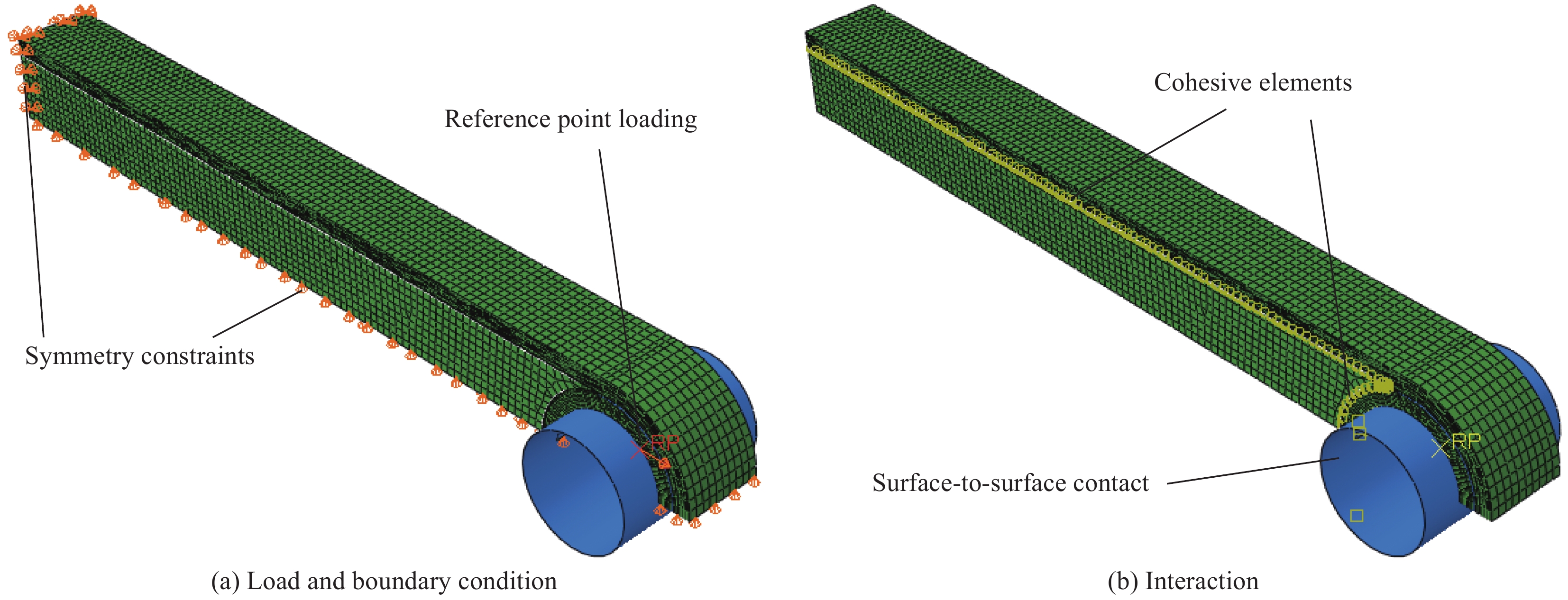
图 5 基础型缠绕接头受拉构型有限元模型约束加载示意图
Figure 5. Schematic diagram of constraint and load for finite element model of basic winding joint tension configuration

图 6 拉伸工况下基础型缠绕接头受拉构型载荷-位移曲线
Figure 6. Load-displacement curve of basic winding joint tension configuration under tensile condition

图 7 拉伸工况下基础型缠绕接头受拉构型链环损伤演化
Figure 7. Damage evolution of loop under tensile condition for basic winding joint tension configuration

图 8 压缩工况下基础型缠绕接头受拉构型载荷-位移曲线
Figure 8. Load-displacement curve of basic winding joint tension configuration under compression condition

图 9 压缩工况下基础型缠绕接头受拉构型损伤演化
Figure 9. Damage evolution of basic winding joint tension configuration under compression condition

图 10 基础型缠绕接头受压构型三维模型
Figure 10. 3D model of the basic winding joint compression configuration

图 11 基础型缠绕接头受拉构型和受压构型压缩工况下载荷-位移曲线对比
Figure 11. Comparison of load-displacement curves of basic winding joint tension configuration and compression configuration under compression

图 12 压缩工况下基础型缠绕接头受压构型损伤演化
Figure 12. Damage evolution of basic winding joint compression configuration under compression condition

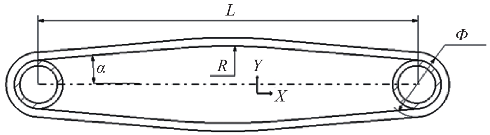
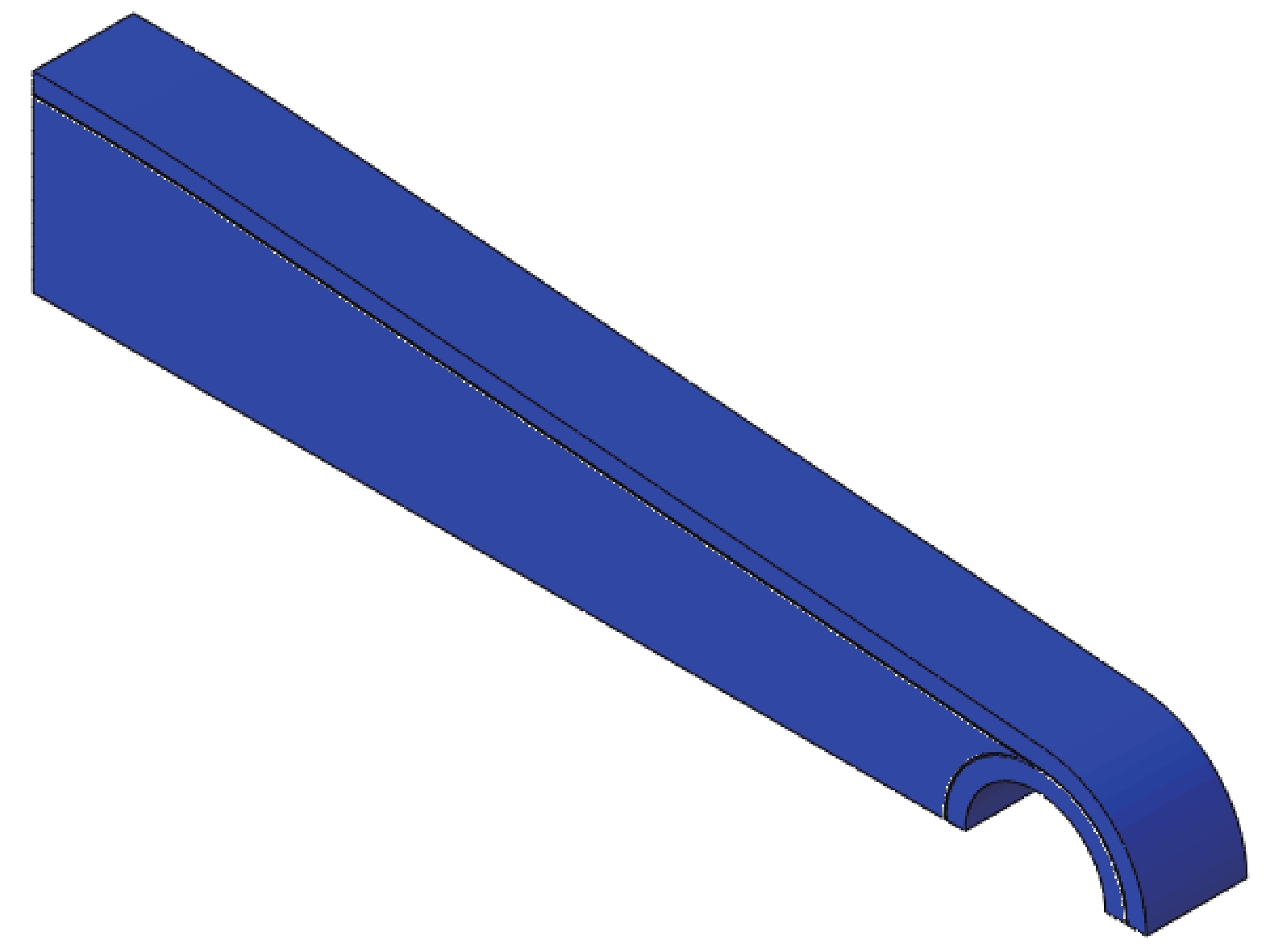
图 14 梭型缠绕接头受拉构型三维模型
Figure 14. 3D model of shuttle winding joint tension configuration

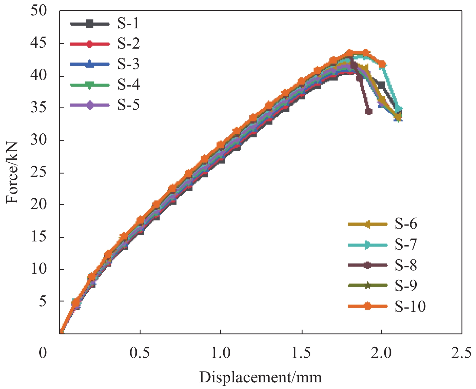
图 16 梭型缠绕接头受拉构型各阶段载荷随α角变化的曲线
Figure 16. Curves of force changing with α angle of shuttle winding joint tension configuration at each stage

图 17 梭型缠绕接头受压构型三维模型
Figure 17. 3D model of shuttle winding joint compression configuration

图 19 压缩工况下模型SY-1~SY-5各损伤起始点随α角的变化
Figure 19. Changes of each damage starting point with α of model SY-1 - SY-5 under compression condition

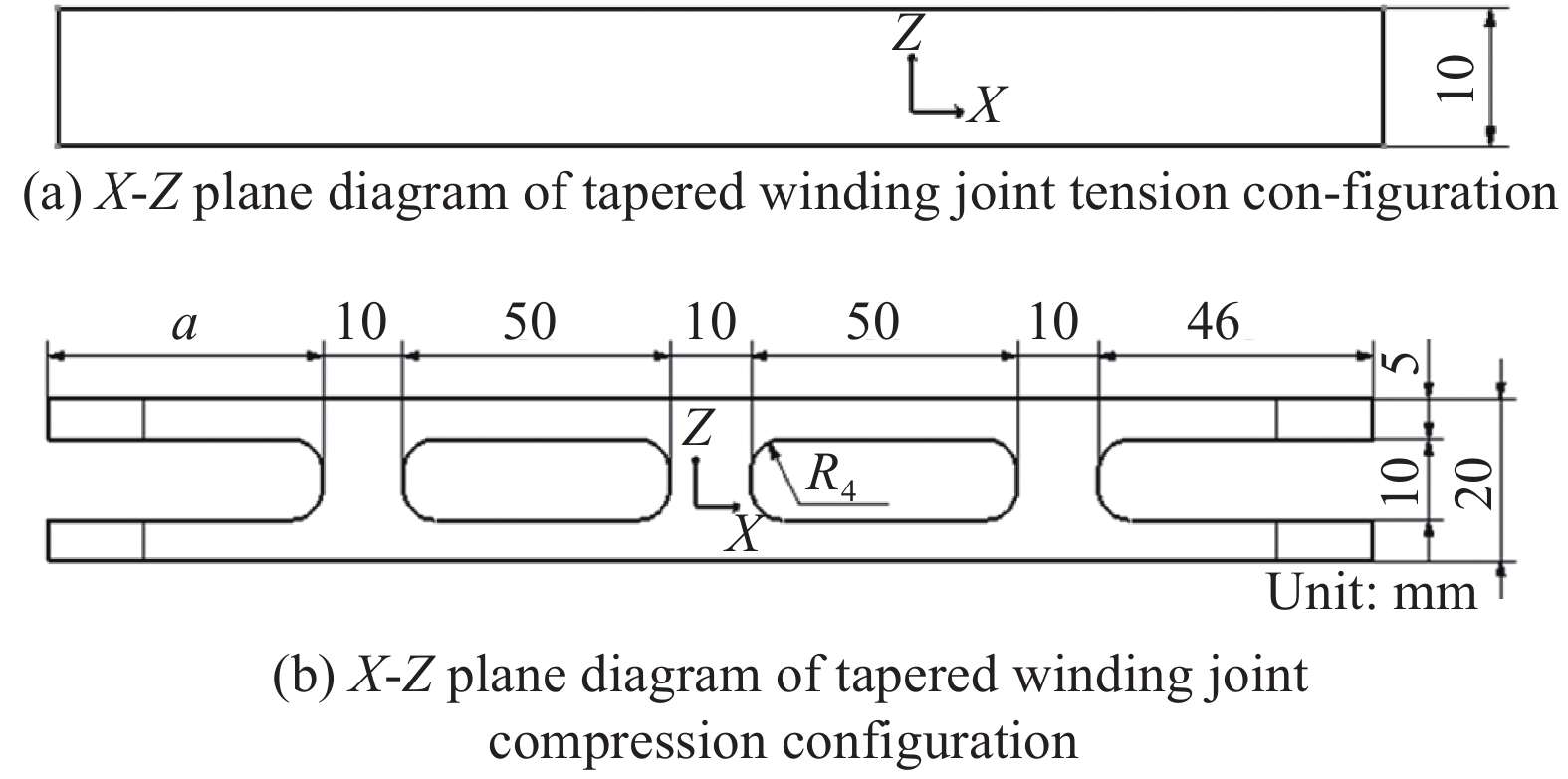
图 21 锥型缠绕接头受拉/压构型X-Z平面示意图
Figure 21. X-Z plane diagram of tapered winding joint tension/compression configuration

图 22 锥型缠绕接头受拉构型三维模型
Figure 22. 3D model of tapered winding joint tension configuration

图 24 模型Z-1~Z-10各阶段载荷随α角变化的曲线
Figure 24. Changes of force with α angle of model Z-1–Z-10 at each stage

图 25 锥型缠绕接头受压构型三维模型
Figure 25. 3D model of tapered winding joint compression configuration

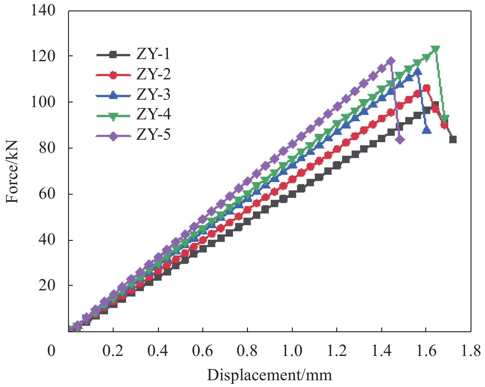
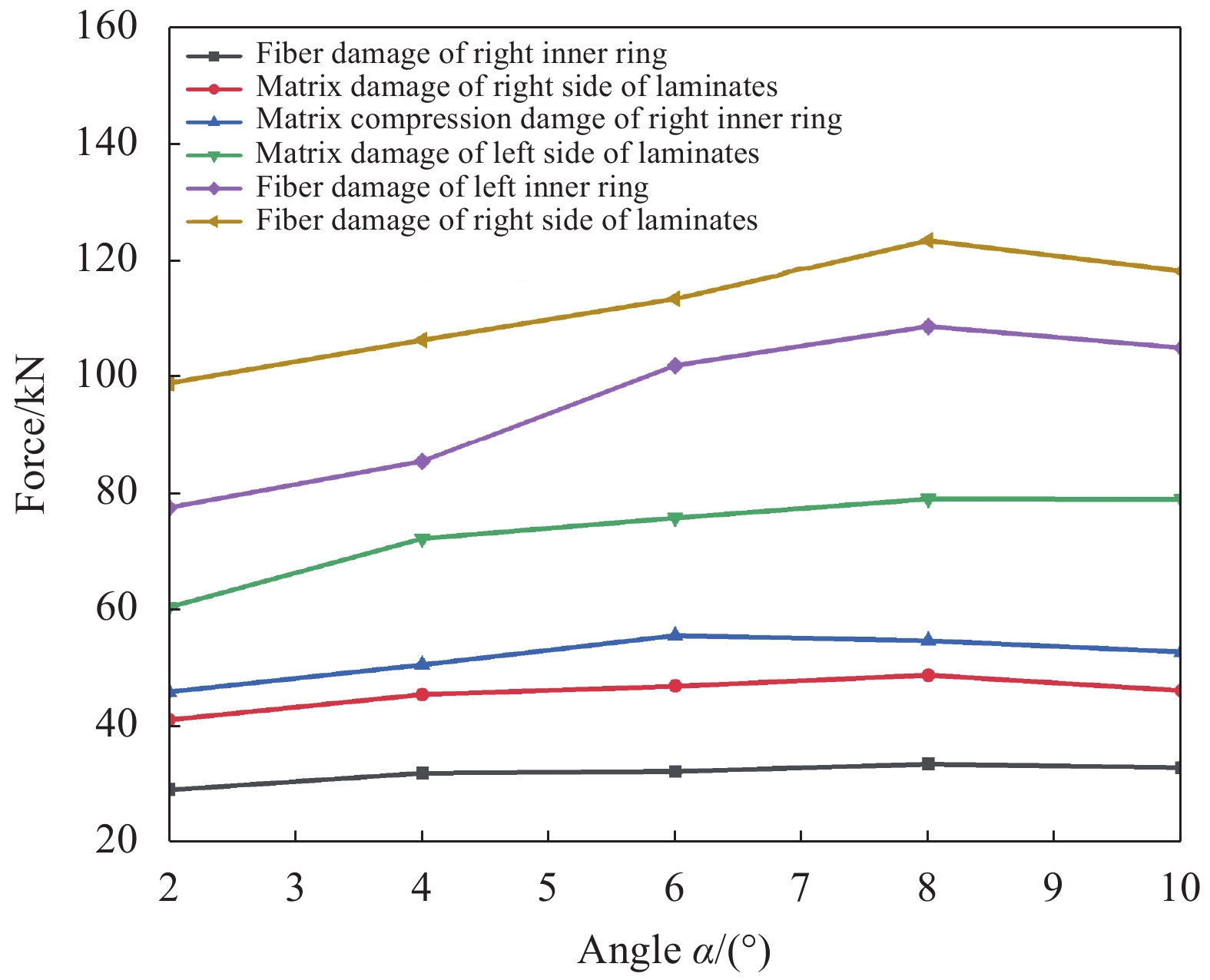
图 27 压缩工况下模型ZY-1~ZY-5各损伤起始点随α角的变化
Figure 27. Changes of each damage starting point with α angle of model ZY-1 - ZY-5 under compression condition
表 1 复合材料参数
Table 1. Composite material parameters
Property CCF300/BA9916-Ⅱ CF3031/BA9916-Ⅱ ${E_1}$/GPa 120 60 ${E_2}$/GPa 7.7 59 ${E_3}$/GPa 7.7 7.7 ${\nu _{12} } = {\nu _{13} } = {\nu _{23} }$ 0.05 0.27 ${G_{12}} = {G_{13}}$/GPa 5.5 6.4 ${G_{23}}$/GPa 5.5 6.4 ${X_{\rm{T}}}$/MPa 1 400 500 ${X_{\rm{C}}}$/MPa 1 300 450 ${Y_{\rm{T}}} = {Z_{\rm{T}}}$/MPa 35 450 ${Y_{\rm{C}}} = {Z_{\rm{C}}}$/MPa 160 455 ${S_{12}} = {S_{13}}$/MPa 163 105 ${S_{23}}$/MPa 86 83 Notes:Ei (i, j=1, 2, 3)—Elastic modulus in the direction of fibre, perpendicular to the fibre in the plane and out of plane; XT, YT and ZT—Tensile strength in the three directions above, respectively; XC, YC and ZC—Compress strength in the three directions above, respectively; νij, Gij and Sij (i, j=1, 2, 3)—Poisson’s ratio, shear modulus and shear strength for 1-2, 1-3, 2-3 plane, respectively.  下载: 导出CSV
表 2 J-116B结构胶材料参数
Table 2. Material parameters of J-116B
$E/{E_{{\rm{nn}}}}$/(MPa·mm−1) ${G_1}/{E_{{\rm{ss}}}}$/(MPa·mm−1) ${G_2}/{E_{{\rm{tt}}}}$/(MPa·mm−1) $t_{\rm{n}}^0$/MPa $t_{\rm{s}}^0$/MPa $t_{\rm{t}}^0$/MPa 1000 300 300 20 30 30 Notes:$E/{E_{{\rm{nn}}}}$, ${G_1}/{E_{{\rm{ss}}}}$ and ${G_2}/{E_{{\rm{tt}}}}$—Interface stiffness for three directions, respectively; $t_{\rm{n}}^0$, $t_{\rm{t}}^0$ and $t_{\rm{t}}^0$—Interface strength for three directions, respectively.
下载: 导出CSV
表 3 梭型缠绕接头模型编号
Table 3. Model number of shuttle winding joint
Tension Compression Model Angle/(°) model Angle/(°) S-1 1 SY-1 2 S-2 2 SY-2 4 S-3 3 SY-3 6 S-4 4 SY-4 8 S-5 5 SY-5 10 S-6 6 S-7 7 S-8 8 S-9 9 S-10 10
下载: 导出CSV
表 4 模型S-1~S-10各阶段载荷及对应位移
Table 4. Loads and corresponding displacements of model S-1 - S-10 at each stage
Stage Property S-1 S-2 S-3 S-4 S-5 S-6 S-7 S-8 S-9 S-10 Initial damage of interface Force/kN 10.92 11.15 11.31 11.48 11.65 11.81 11.97 12.09 12.20 12.32 Displacement/mm 0.30 0.30 0.30 0.30 0.30 0.30 0.30 0.30 0.30 0.30 Failure of interface Force/kN 34.96 35.46 35.78 36.10 36.42 36.62 36.87 37.05 37.19 37.35 Displacement/mm 1.40 1.40 1.40 1.40 1.40 1.40 1.40 1.40 1.40 1.40 Initial damage of chain link Force/kN 36.85 37.33 37.64 37.95 38.26 38.51 38.70 38.86 39.00 39.14 Displacement/mm 1.50 1.50 1.50 1.50 1.50 1.50 1.50 1.50 1.50 1.50 Failure of winding joint Force/kN 40.66 40.78 41.05 41.36 41.67 42.21 42.74 43.28 43.42 43.59 Displacement/mm 1.80 1.80 1.80 1.80 1.80 1.80 1.80 1.80 1.90 1.90
下载: 导出CSV
表 5 压缩工况下模型SY-1~SY-5损伤起始点
Table 5. Damage starting points of model SY-1 - SY-5 under compression condition
Stage Property SY-1 SY-2 SY-3 SY-4 SY-5 Matrix compression damage of inner ring Force/kN 50.97 49.44 52.30 47.98 49.83 Displacement/mm 0.72 0.64 0.64 0.56 0.56 Matrix damage of laminates Force/kN 50.97 49.44 52.30 47.98 49.83 Displacement/mm 0.72 0.64 0.64 0.56 0.56 Fiber tensile damage of inner ring Force/kN 56.76 55.51 58.74 54.73 57.01 Displacement/mm 0.80 0.72 0.72 0.64 0.64 Fiber damage of laminates Force/kN 101.90 104.82 110.93 109.51 106.93 Displacement/mm 1.44 1.36 1.36 1.28 1.20
下载: 导出CSV
表 6 锥形缠绕接头模型编号
Table 6. model number of tapered winding joint
Tension Compression No. Angle/(°) No. Angle/(°) Z-1 1 Z-1 2 Z-2 2 Z-2 4 Z-3 3 Z-3 6 Z-4 4 Z-4 8 Z-5 5 Z-5 10 Z-6 6 Z-7 7 Z-8 8 Z-9 9 Z-10 10
下载: 导出CSV
表 7 模型Z-1~Z-10各阶段载荷及对应位移
Table 7. Loads and corresponding displacements of model Z-1-Z-10 at each stage
Stage Property Z-1 Z-2 Z-3 Z-4 Z-5 Z-6 Z-7 Z-8 Z-9 Z-10 Initial damage of interface Force/kN 9.53 10.02 10.76 11.31 12.11 11.82 11.52 11.22 10.86 10.52 Displacement/mm 0.24 0.24 0.24 0.24 0.32 0.32 0.32 0.32 0.32 0.32 Failure of interface Force/kN 34.64 36.01 36.48 36.51 36.65 35.92 35.40 34.50 34.11 33.41 Displacement/mm 1.28 1.28 1.28 1.28 1.28 1.28 1.28 1.28 1.28 1.28 Initial damage of chain link Force/kN 37.46 38.88 39.46 39.64 39.90 40.15 40.59 41.11 41.57 42.17 Displacement/mm 1.44 1.44 1.44 1.44 1.44 1.52 1.52 1.60 1.68 1.76 Failure of winding joint Force/kN 40.82 41.71 42.17 42.81 43.26 43.27 43.59 43.75 44.05 44.14 Displacement/mm 1.76 1.68 1.68 1.68 1.68 1.76 1.76 1.84 1.92 2.00
下载: 导出CSV
表 8 压缩工况下模型ZY-1~ZY-5损伤起始点
Table 8. Damage starting points of model ZY-1-ZY-5 under compression condition
Stage Property ZY-1 ZY-2 ZY-3 ZY-4 ZY-5 Fiber tensile damage of right inner ring Force/kN 29.00 31.87 32.12 33.43 32.79 Displacement/mm 0.48 0.48 0.44 0.44 0.40 Matrix damage of right side of laminates Force/kN 40.98 45.32 46.78 48.66 45.98 Displacement/mm 0.68 0.68 0.64 0.64 0.56 Matrix compression damage of right inner ring Force/kN 45.79 50.47 55.45 54.53 52.63 Displacement/mm 0.76 0.76 0.76 0.72 0.64 Matrix damage of left side of laminates Force/kN 60.34 72.10 75.66 78.92 78.83 Displacement/mm 1.00 1.08 1.04 1.04 0.96 Fiber tensile damage of left inner ring Force/kN 77.42 85.36 101.89 108.60 104.93 Displacement/mm 1.28 1.28 1.40 1.44 1.28 Fiber damage of right side of laminates Force/kN 98.89 106.29 113.34 123.40 118.11 Displacement/mm 1.64 1.60 1.56 1.64 1.44
下载: 导出CSV
-
[1] 杜善义. 先进复合材料与航空航天[J]. 复合材料学报, 2007, 24(1):1-12. doi: 10.3321/j.issn:1000-3851.2007.01.001DU S Y. Advanced composite materials and aerospace engineering[J]. Acta Materiae Compositae Sinica,2007,24(1):1-12(in Chinese). doi: 10.3321/j.issn:1000-3851.2007.01.001 [2] 赵渠森. 先进复合材料手册[M]. 北京: 机械工业出版社, 2003: 872-873.ZHAO Q S. Handbook of Advanced Composite Materials[M]. Beijing: Mechanical Industry Press, 2003: 872-873(in Chinese). [3] 王琪. 耳片接头结构的拓扑优化与参数化设计研究[D]. 南京: 南京航空航天大学, 2016.WANG Q. Research on topology optimization and parametric design of lug connectors[D]. Nanjing: Nanjing University of Aeronautics & Astronautics, 2016(in Chinese). [4] SCHULZ D. Develpoment of the A320 fin in modern composite fiber construction[C]//ICAS-80-16.2. 1988: 1828. [5] HAVAR T, DRECHSLER K. Design and progressive failure analysis of 3d-reinforced composite force introduction loops[C]. 49th AIAA/ASME/ASCE/AHS/ASC Structures, Structural Dynamics, and Materials Conference. 2008. [6] HAVAR T, MIDDENDORF J, WERCHNER C. Design and manufacturing of composite aerospace load introduction structures[C]//52th AIAA/ASME/ASCE/AHS/ASC Structures, Structural Dynamics and Materials Conference. 2011: 1713. [7] 张文荣. 复合材料耳片接头承载能力试验[J]. 洪都科技, 2001(1):38-42.ZHANG W R. Bearing capacity test of composite lug joint[J]. Hongdu Science and Technology,2001(1):38-42(in Chinese). [8] 孙旋, 童明波, 陈智, 等. 碳纤维复合材料接头力学性能试验与仿真分析[J]. 复合材料学报, 2016, 33(11):2517-2527.SUN X, TONG M B, CHEN Z, et al. Test and simulation analysis of mechanical properties of carbon fiber composite joints[J]. Acta Materiae Compositae Sinica,2016,33(11):2517-2527(in Chinese). [9] 郑锡涛, 孙秦, 柴亚南, 等. 复合材料编织接头承载能力的试验研究[J]. 航空学报, 2007, 28(2):348-351. doi: 10.3321/j.issn:1000-6893.2007.02.019ZHENG X T, SUN Q, CHAI Y N, et al. Experimental study on bearing capacity of composite braided joints[J]. Acta Aeronautica Sinica,2007,28(2):348-351(in Chinese). doi: 10.3321/j.issn:1000-6893.2007.02.019 [10] 郑锡涛, 郭英男, 孙秦, 等. 三维四向编织复合材料接头承载能力分析[J]. 机械强度, 2006, 28(6):923-926. doi: 10.3321/j.issn:1001-9669.2006.06.027ZHENG X T, GUO Y N, SUN Q, et al. Analysis of bearing capacity of 3d four-way braided composite joints[J]. Mechanical Strength,2006,28(6):923-926(in Chinese). doi: 10.3321/j.issn:1001-9669.2006.06.027 [11] 程家林. 层压复合材料连接接头设计及其在大飞机中的应用[J]. 航空学报, 2008(3):640-644. doi: 10.3321/j.issn:1000-6893.2008.03.017CHENG J L. Laminated composite joint design and its application in large aircraft[J]. Acta Aeronautica Sinica,2008(3):640-644(in Chinese). doi: 10.3321/j.issn:1000-6893.2008.03.017 [12] 史坚忠. 复合材料主承力接头设计技术研究[D]. 南京: 南京航空航天大学, 1999.SHI J Z. Research on design technology of composite main bearing joint[D]. Nanjing: Nanjing University of Aeronautics & Astronautics, 1999(in Chinese). [13] 史坚忠, 黄维杨. 复合材料承力接头设计的相关理论与应用概述[J]. 华东交通大学学报, 1998, 12(15):38-44.SHI J Z, HUANG W Y. Theory and application of composite bearing joint design[J]. Journal of east China Jiaotong University,1998,12(15):38-44(in Chinese). [14] 雷良超, 周光明, 陆方舟, 等. 复合材料缠绕接头拉伸失效性能有限元分析[J]. 兵器装备工程学报, 2018, 39(4):174-178. doi: 10.11809/bqzbgcxb2018.04.037LEI L C, ZHOU G M, LU F Z, et al. Finite element analysis on tensile properties of composite winding joint[J]. Journal of Ordnance Equipment Engineering,2018,39(4):174-178(in Chinese). doi: 10.11809/bqzbgcxb2018.04.037 [15] 雷良超. 复合材料缠绕接头力学性能研究[D]. 南京: 南京航空航天大学, 2018.LEI L C. Research on mechanical properties of the winding composite lug[D]. Nanjing: Nanjing University of Aeronautics & Astronautics, 2018(in Chinese). [16] HASHIN Z. Failure criteria for unidirectional fiber compo-sites[J]. Journal of Applied Mechanics,1980,47(2):329-334. doi: 10.1115/1.3153664 [17] CAMANHO P P. A progressive damage model for mechanically fastened joints in composite laminates[J]. Journal of Composite Materials,1999,33(24):2248-2280. doi: 10.1177/002199839903302402 -

 下载:
下载:


 点击查看大图

计量
- 文章访问数: 1215
- HTML全文浏览量: 387
- PDF下载量: 95
- 被引次数: 0
