


Axial compression failure behavior of typical bolted CFRP thin-walled C-channels: Experimental and numerical simulation
-
摘要: 为了研究典型螺栓连接碳纤维增强树脂复合材料(CFRP)薄壁C型柱的轴压失效模式及吸能特性,进行了5组不同铺层方式C型柱的准静态轴压试验,即[0/90]4s、[±45]4s、[±45/902/04]s、[±45/90/02/90/02]s、[90/±45/0]2s,获得其失效形貌及载荷-位移曲线。采用Lavadèze单层壳单元模型、Puck-Yamada失效准则、层间胶粘单元及螺栓模型,建立C型柱层合壳模型进行轴压仿真,并与试验失效形貌、载荷-位移曲线及吸能特性评估指标进行对比分析。结果表明:0°、±45°、90°纤维可以显著影响C型柱轴压失效模式及吸能特性。在轴压载荷下,±45°纤维铺设C型柱发生局部屈曲失效模式,吸能特性差。±45°纤维铺设在外部,0°和90°纤维交替铺设在内部的C型柱,其轴压失效过程平稳,吸能特性好。与C型柱轴压试验结果相比,层合壳模型获得的整体变形和局部失效形貌吻合较好,载荷-位移曲线变化趋势和吸能特性评价指标基本一致。研究结果对CFRP薄壁C型柱吸能设计具有一定的指导意义。Abstract: Aiming at studying the axial compressive failure mode and energy-absorbing characteristics of typical bolted carbon fiber reinforced polymer (CFRP) thin-walled C-channels, the quasi-static axial compression tests of five groups of C-channels with different layups, i.e. [0/90]4s, [±45]4s, [±45/902/04]s, [±45/90/02/90/02]s and [90/±45/0]2s, were conducted. The failure morphology and load-displacement curves were obtained. Considering the Lavadèze single-layer shell element model, Puck-Yamada failure criterion, interlayer cohesive element and bolt connection model, the stacked shell models of C-channels were established to perform the axial compression simulation, and the failure morphology, force-displacement curve and energy-absorbing metrics were compared with the test and analyzed. The results show that the 0°, ±45° and 90° fibers can significantly affect the axial compression failure mode and energy-absorbing characteristics of C-channels. Under the axial compression loading, the local buckling failure mode occurs for the C-channels with ± 45 ° fiber, resulting in poor energy-absorbing characteristics. For the C-channels with outside ± 45° fiber, and the inside 0° and 90° fiber, the axial compression failure process is stable, resulting in good energy-absorbing characteristics. The overall deformation and local failure morphology obtained by stacked shell models are in good agreement with the test results, the force-displacement curves and the energy-absorbing metrics are basically consistent with the test results. The research results can provide guidance for energy-absorbing design of CFRP thin-walled C-channels.
-

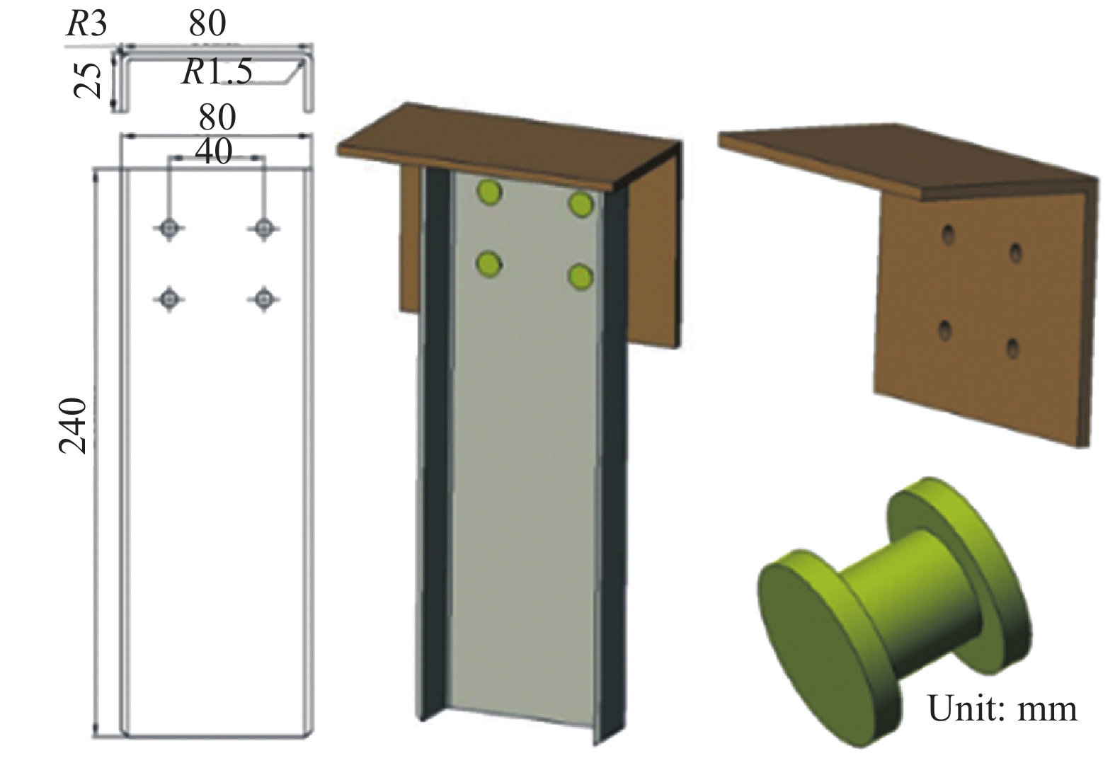
图 1 螺栓连接碳纤维增强树脂复合材料(CFRP)薄壁C型柱试件
Figure 1. Bolted carbon fiber reinforced polymer (CFRP) thin-walled C-channels

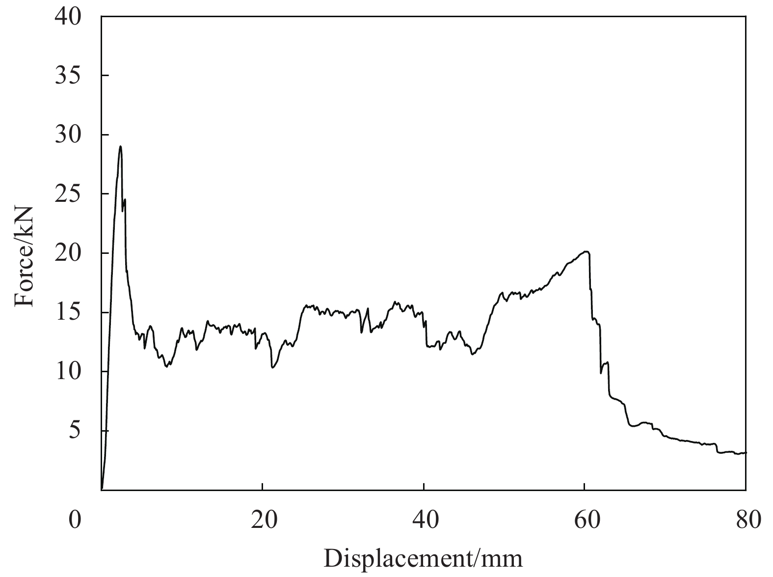
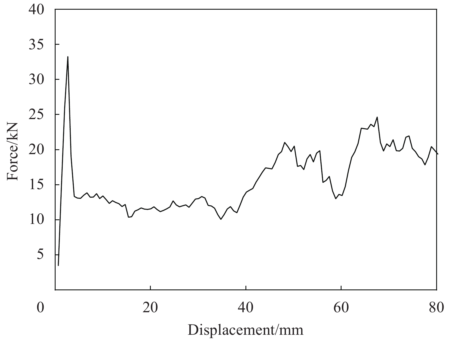
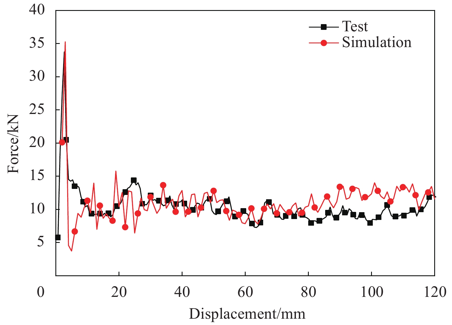
图 3 [0/90]4s螺栓连接CFRP薄壁C型柱载荷-位移曲线
Figure 3. Force-displacement curve of bolted CFRP thin-walled [0/90]4s C-channel
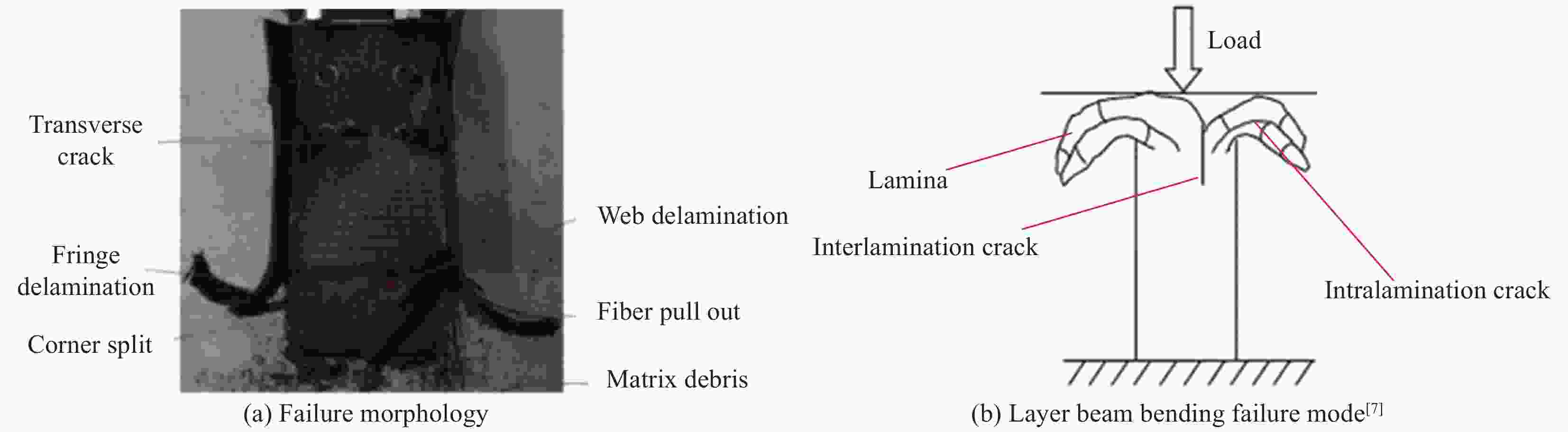
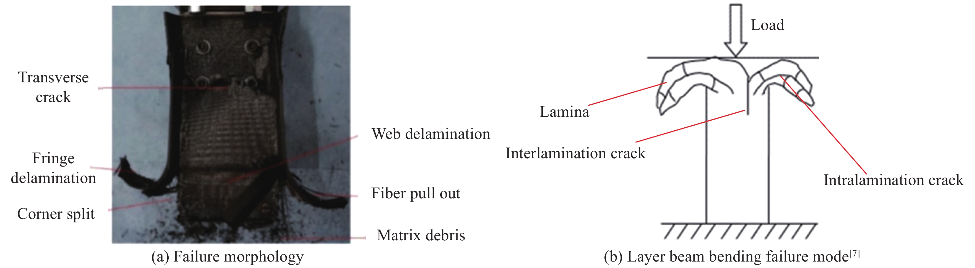
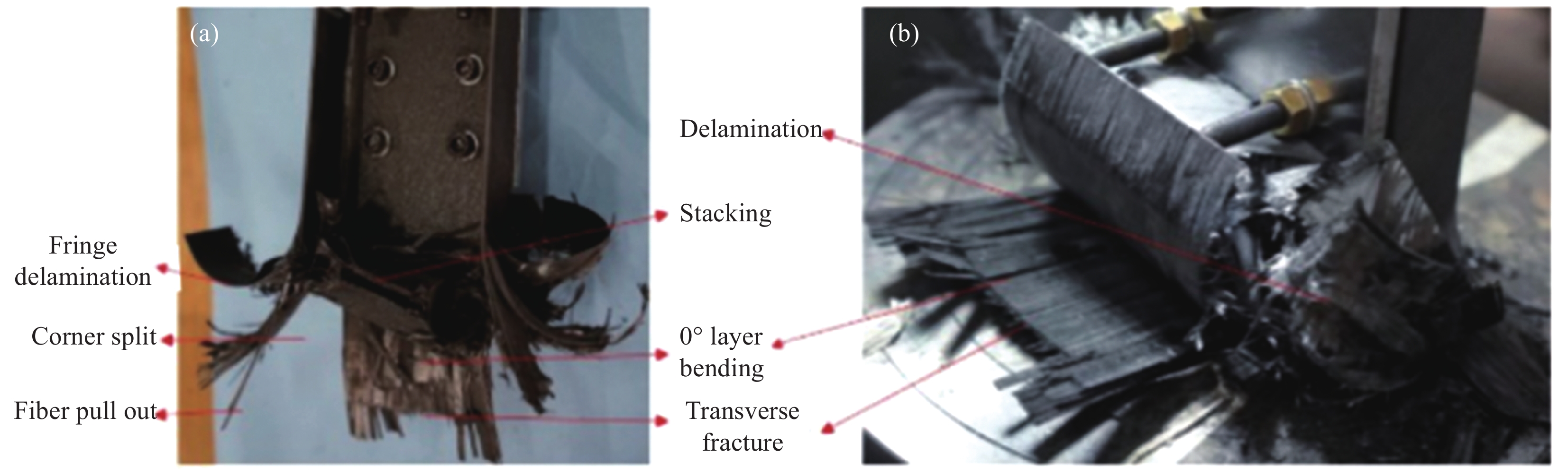
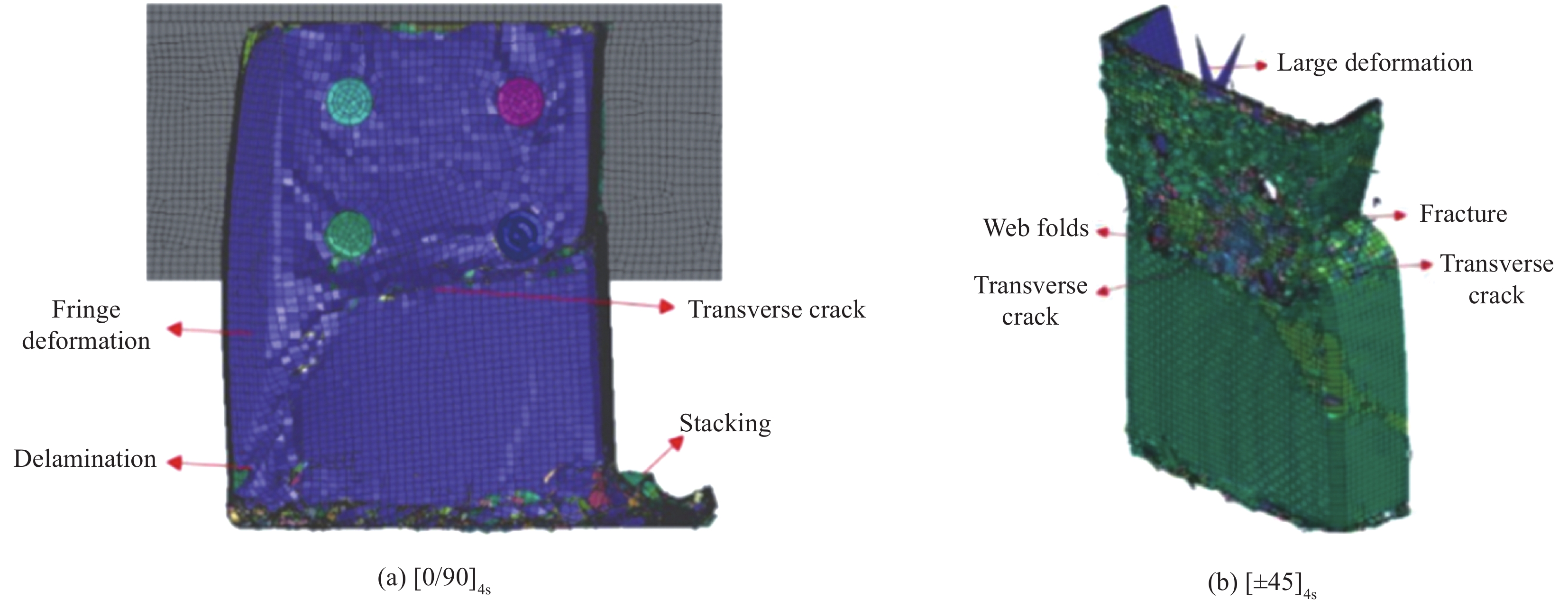
图 4 [0/90]4s螺栓连接CFRP薄壁C型柱失效形貌及层束弯曲失效模式
Figure 4. Failure morphology and layer beam bending mode of bolted CFRP thin-walled [0/90]4s C-channel

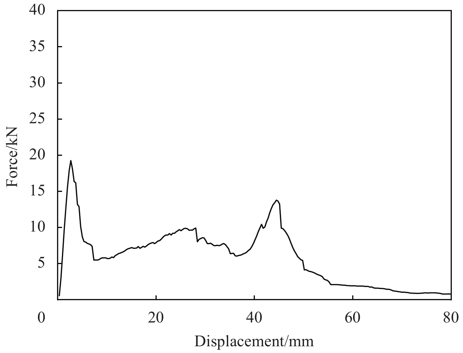
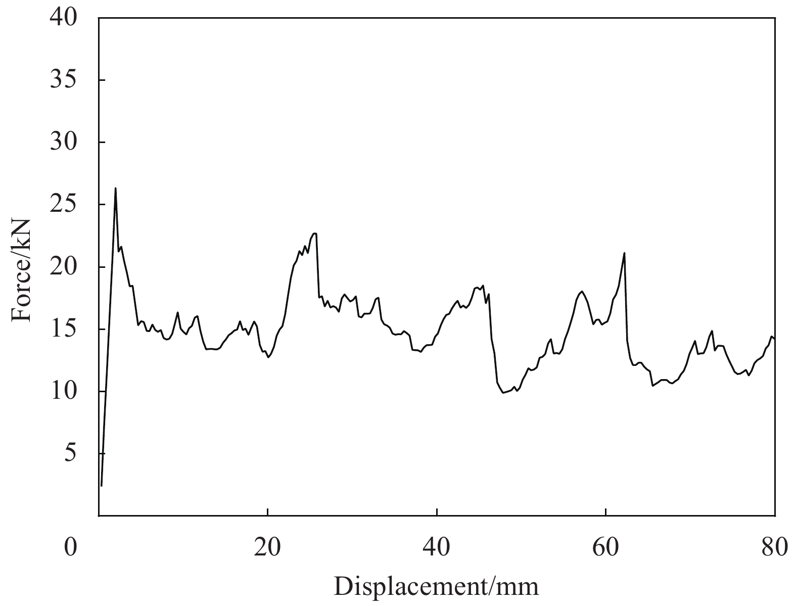
图 5 [±45]4s螺栓连接CFRP薄壁C型柱载荷-位移曲线
Figure 5. Force-displacement curve of bolted CFRP thin-walled [±45]4s C-channel
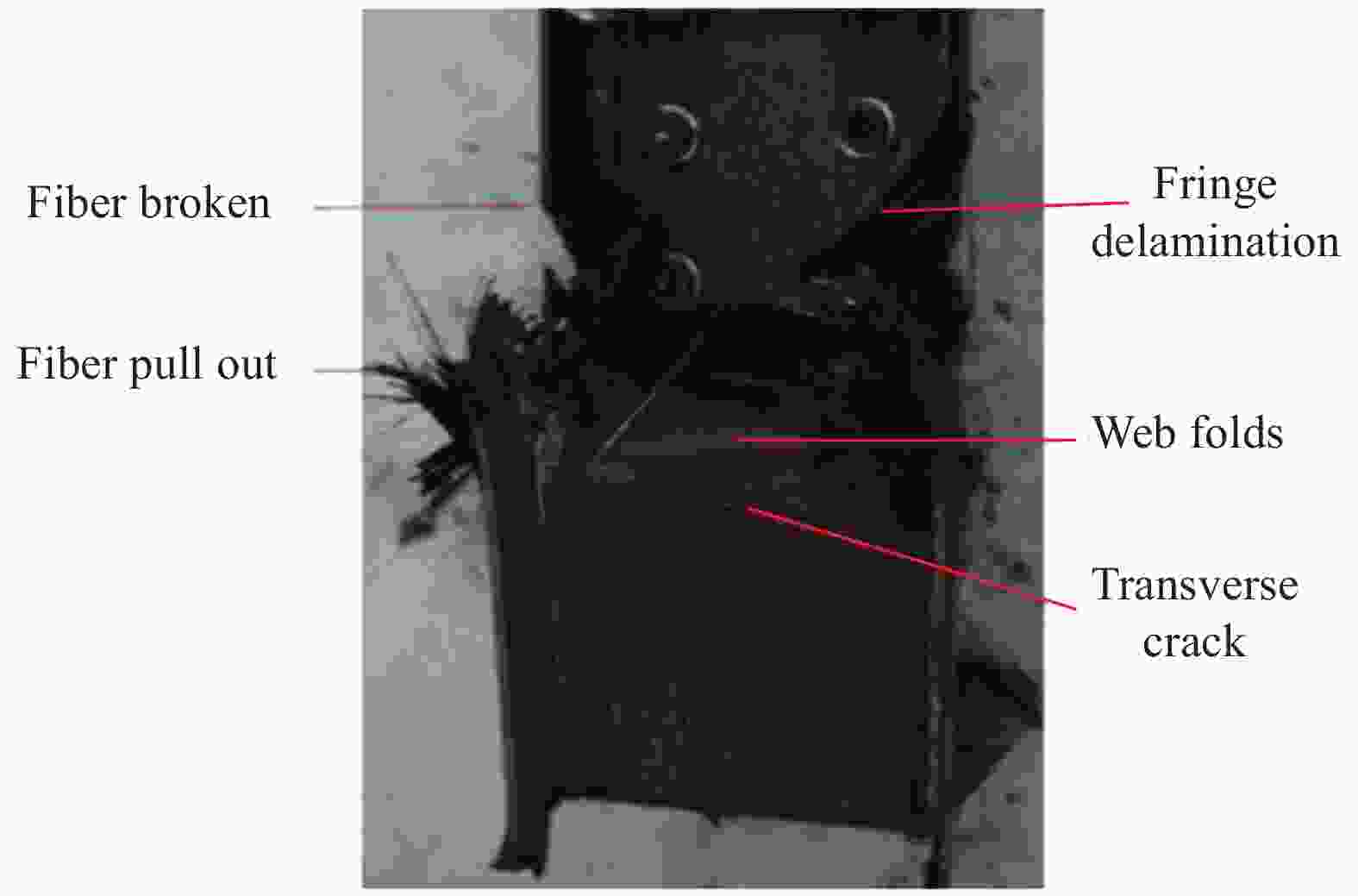
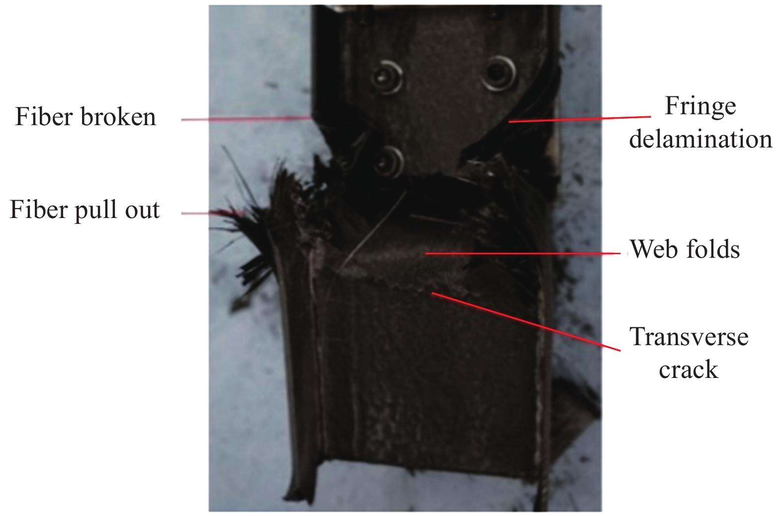
图 6 [±45]4s 螺栓连接CFRP薄壁C型柱失效形貌
Figure 6. Failure morphology of bolted CFRP thin-walled [±45]4s C-channel

图 7 [±45/902/04]s螺栓连接CFRP薄壁C型柱载荷-位移曲线
Figure 7. Force-displacement curve of bolted CFRP thin-walled [±45/902/04]s C-channel
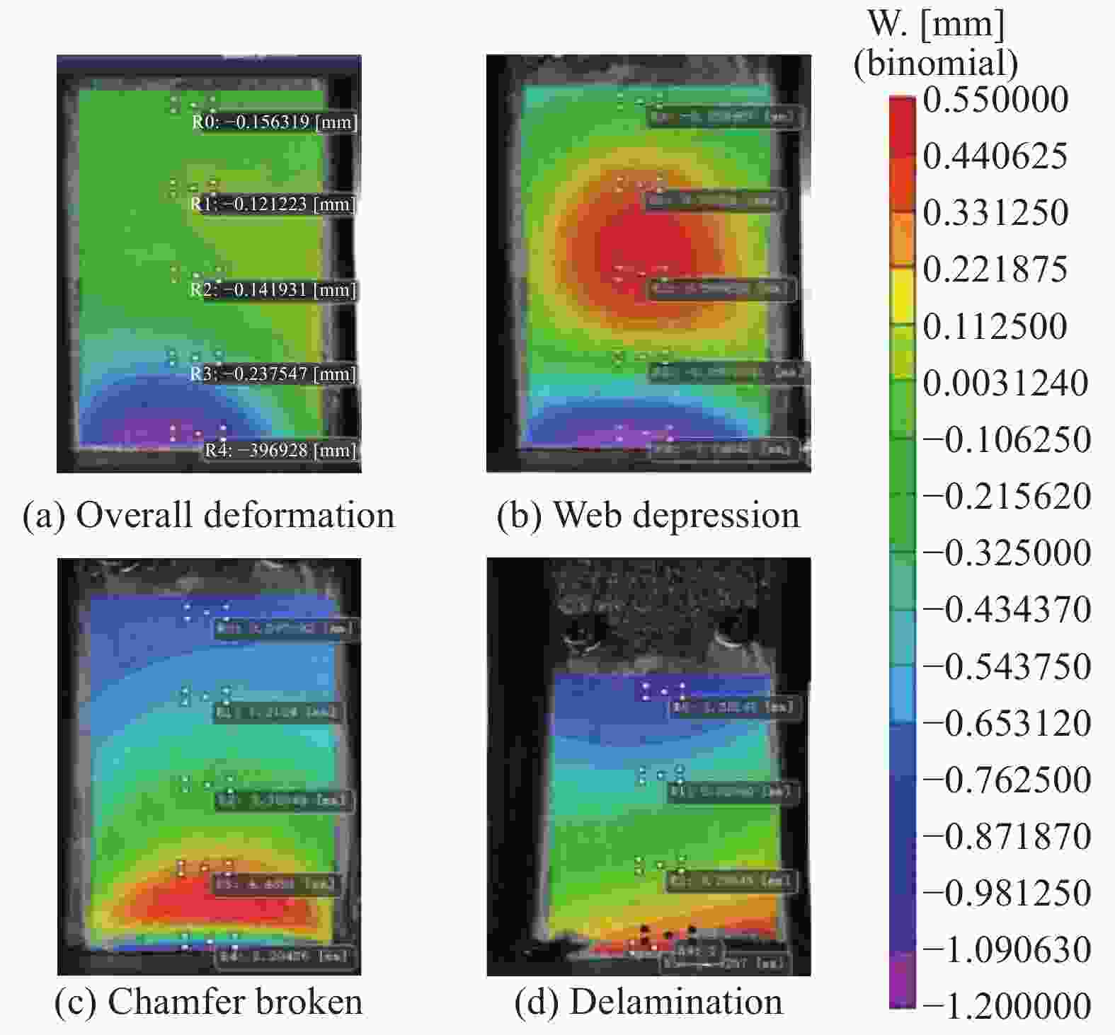
图 8 [±45/902/04]s螺栓连接CFRP薄壁C型柱离面位移云图
Figure 8. Out-plane displacement of bolted CFRP thin-walled [±45/902/04]s C-channel

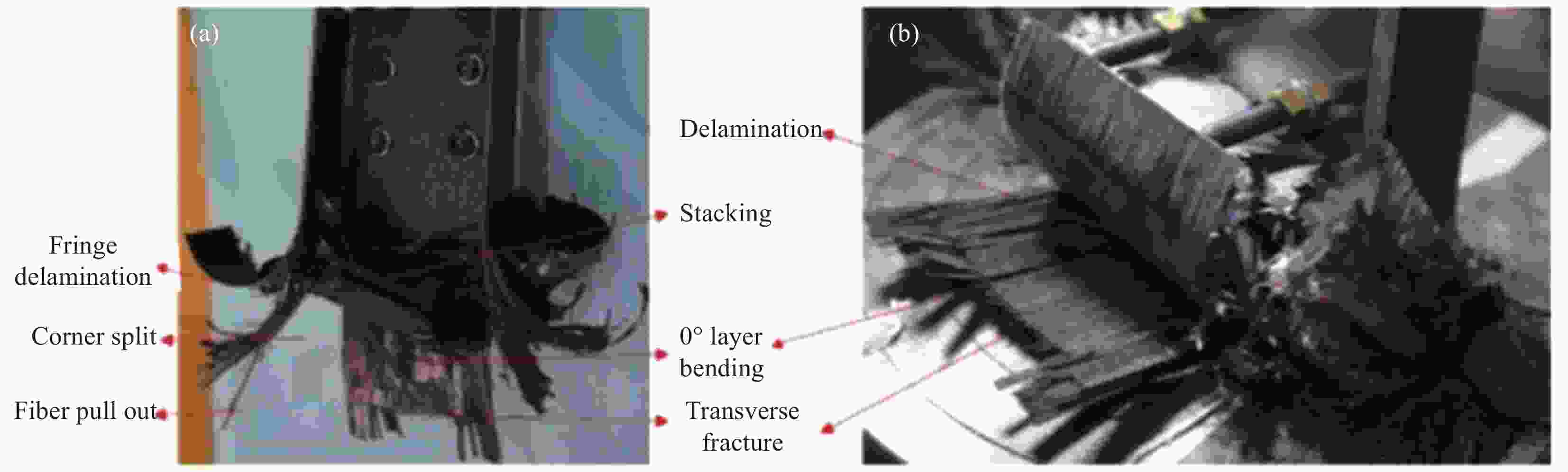
图 10 [±45/902/04]s螺栓连接CFRP薄壁C型柱失效形貌
Figure 10. Failure morphology of bolted CFRP thin-walled [±45/902/04]s C-channel

图 11 [±45/90/02/90/02]s螺栓连接CFRP薄壁C型柱载荷-位移曲线
Figure 11. Force-displacement curve of bolted CFRP thin-walled [±45/90/02/90/02]s C-channel
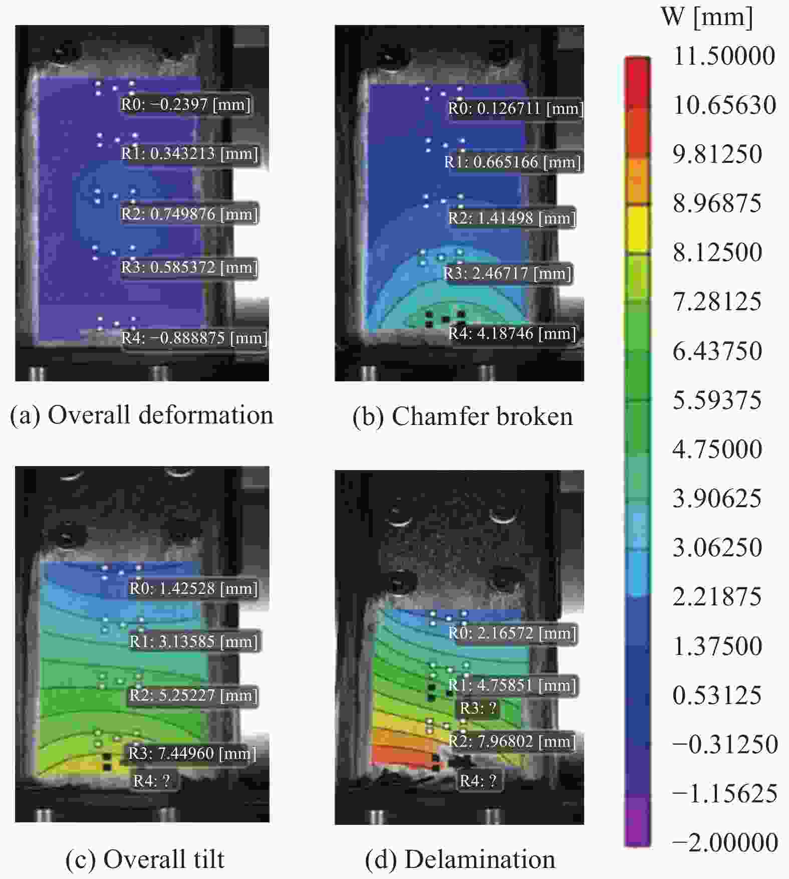
图 12 [±45/90/02/90/02]s 螺栓连接CFRP薄壁C型柱离面位移云图
Figure 12. Out-plane displacement of bolted CFRP thin-walled [±45/90/02/90/02]s C-channel

图 13 [±45/90/02/90/02]s 螺栓连接CFRP薄壁C型柱失效形貌
Figure 13. Failure morphology of bolted CFRP thin-walled [±45/90/02/90/02]s C-channel

图 14 [90/±45/0]2s螺栓连接CFRP薄壁C型柱载荷-位移曲线
Figure 14. Force-displacement curve of bolted CFRP thin-walled [90/±45/0]2s C-channel

图 15 [90/±45/0]2s螺栓连接CFRP薄壁C型柱失效形貌及局部屈曲失效模式
Figure 15. Failure morphology and local buckling failure mode of bolted CFRP thin-walled [90/±45/0]2s C-channel

图 16 螺栓连接CFRP薄壁C型柱一阶屈曲模态
Figure 16. First buckling mode of bolted CFRP thin-walled C-channels

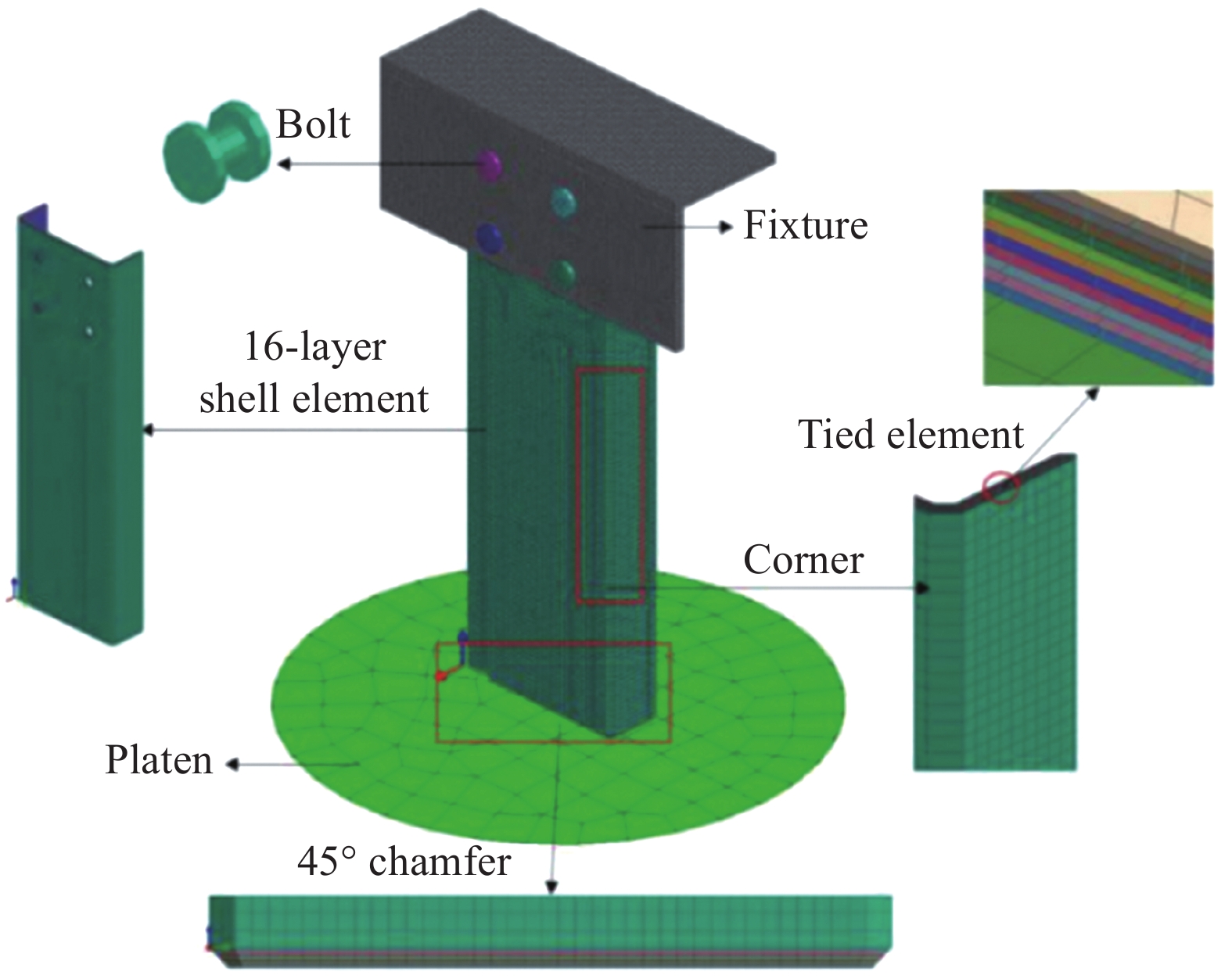
图 17 螺栓连接CFRP薄壁C型柱有限元模型
Figure 17. Finite element model of bolted CFRP thin-walled C-channel

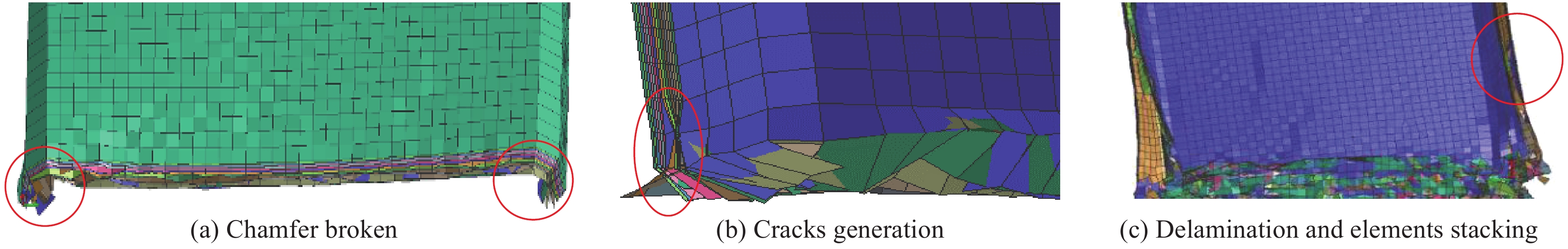
图 18 螺栓连接CFRP薄壁C型柱轴压仿真失效形貌
Figure 18. Simulated failure mode of bolted CFRP thin-walled C-channel
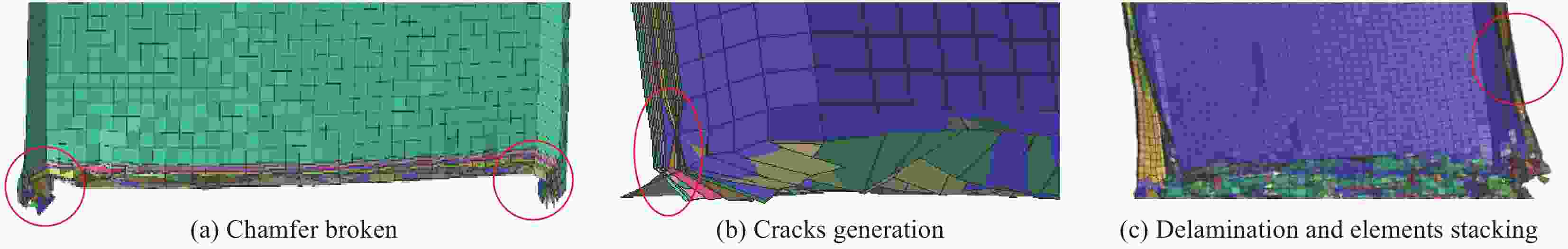
图 19 [±45/90/02/90/02]s 螺栓连接CFRP薄壁C型柱仿真失效形貌
Figure 19. Simulated failure mode of bolted CFRP thin-walled [±45/90/02/90/02]s C-channel
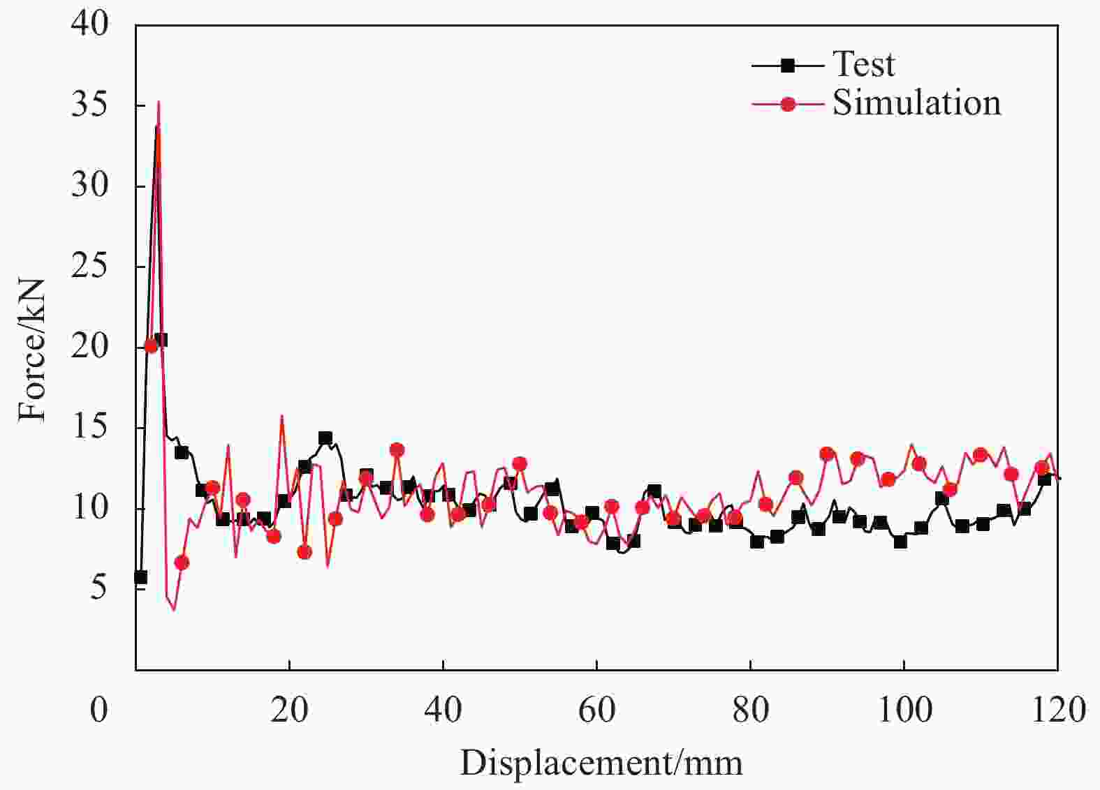
图 20 [±45/90/02/90/02]s螺栓连接CFRP薄壁C型柱载荷-位移曲线及失效过程
Figure 20. Force-displacement curve and failure process of bolted CFRP thin-walled [±45/90/02/90/02]s C-channel
表 1 USN15000 CFRP性能参数
Table 1. USN15000 CFRP performance parameters
Definition Value Density/(g·cm−3) 1.5 Poisson's ratio ν12 0.3 0° tension modulus/GPa 134 0° tension strength/MPa 2158 0° compression strength/MPa 1000 90° tension modulus/GPa 8.3 90°tension strength/MPa 42 90° compression strength/GPa 9 90° compression strength/MPa 172 ±45° in-plan shear modulus/GPa 3.8 ±45° in-plan shear modulus/MPa 75  下载: 导出CSV
表 2 螺栓连接CFRP薄壁C型柱Fb和Fmax对比
Table 2. Comparison on Fb and Fmax among bolted CFRP thin-walled C-channels
Layup Fb/kN Fmax/kN [0/90]4s 37.15 29.03 [±45]4s 30.02 19.08 [±45/902/04]s 45.89 28.04 [±45/90/02/90/02]s 46.15 34.12 [90/±45/0]2s 43.84 27.14 Notes: Fb—Critical buckling load; Fmax—Initial peak crush load.
下载: 导出CSV
表 3 螺栓连接CFRP薄壁C型柱有限元模型中的材料参数
Table 3. Material parameters for bolted CFRP thin-walled C-channel finite element models
Parameter Value Single layer plate density, RHO/(g·cm−3) 1.5 Elastic modulus in fiber tensile direction, E0t1/GPa 134 Elastic modulus in perpendicular fiber direction, E0t2/GPa 8.3 Elastic modulus in fiber compressive direction, E0c1/GPa 116 1,2 plane shear modulus, G012 3.69 Poisson's ratio ν12/GPa 0.3 Critical shear damage limit, Yc/GPa1/2 0.08 Initional shear damage limit, Y0/GPa1/2 0.02 Critical transverse damage limit, Y’c/GPa1/2 0.08 Initial transverse damage limit, Y’0/GPa1/2 0.02 Shear/transverse damage coupling factor 0 Fiber-matrix interface brittle transverse damage limit,
Y’s/GPa1/20.08 Element shear fracture damage limit, Yr/GPa1/2 0.08 Maximum allowable value of shear damage and transverse damage, Dmax 1 Fiber tensile initial strain 0.0217 Fiber tensile critical strain 0.025 Compressive modulus correction factor 0 Fiber compressive initial strain 0.01128 Fiber compression critical strain 0.01228 Tensile transverse strength of matrix, R22+/MPa 0.042 Compressive strength of matrix, R22-/MPa 0.172 Shear strength of matrix, R12/MPa 0.075 Post-damage factor of matrix 0.96 Slope 1 0.27 Slope 2 0.27 Fiber tensile failure strain, $\varepsilon _{11}^ + $ 0.02 In-plane shear failure strain, $\varepsilon _{12}^ + $ 0.224 Out-of-plane shear failure strain, $\varepsilon _{13}^ + $ 0.224 Fiber compression failure strain, $\varepsilon _{11}^ - $ 0.02 In-plane shear failure strain in compression, $\varepsilon _{12}^ - $ 0.224 Out-of-plane shear failure strain in compression, $\varepsilon _{13}^ - $ 0.224
下载: 导出CSV
表 4 303-Slink-Elink-Tied单元参数
Table 4. Parameters of 303-Slink-Elink-Tied element
Parameter Value Kinetic energy calculation distance, Hcont/mm 0.3 Elastic modulus, E0/GPa 4 Shear modulus, G0/GPa 2.5 Continuous delamination normal stress/GPa 0.098 Continuous delamination shear stress/GPa 0.094 Type I fracture energy, $G_{\rm{u}}^{\rm{I}}$/(J·mm−2) 0.00047 Type II fracture energy, $G_{\rm{u}}^{{\rm{II}}}$/(J·mm−2) 0.002 Initial delamination normal stress/GPa 0.1 Initial delamination shear stress/GPa 0.1 Cycles of stress reduction 100 Stiffness damping ratio 0.1
下载: 导出CSV
表 5 夹具和螺栓输入参数
Table 5. Material parameters of fixture and bolt
Parameter Value Density, RHO/(kg·mm−3) 7.8×10⁻⁶ Shear modulus, G/GPa 400 Single stress-strain curve yield stress/GPa 2 000 Tangent modulus of bilinear stress-strain curve, Et/GPa 200 Buckling modulus, K/GPa 400
下载: 导出CSV
表 6 螺栓连接CFRP薄壁C型柱仿真与试验吸能特性评价指标对比
Table 6. Comparison on energy-absorbing metrics of bolted CFRP thin-walled C-channels’ between simulation and tests
Layup Energy-absorbing metrics Fmax/kN Fmean/kN Ea/J Es/(kJ·kg−1) [0/90]4s Test 29.03 8.45 996.31 30.10 Simulation 32.01 8.91 1012.17 31.31 Deviation 10.3% 5% 2% 0.6% [±45]4s Test 19.08 5.67 471.03 14.38 Simulation 20.11 5.01 400.82 12.36 Deviation 5% 12% 15% 14% [±45/902/04]s Test 28.04 9.85 1097.48 35.74 Simulation 34.42 9.42 1054.31 34.60 Deviation 21% 4% 4% 3% [±45/90/02/90/02]s Test 34.12 10.23 1259.97 38.35 Simulation 35.21 10.41 1291.61 31.22 Deviation 3% 2% 3% 3% [90/±45/0]2s Test 27.14 9.44 1181.91 33.99 Simulation 30.31 9.21 1134.51 32.51 Deviation 12.2% 2% 4% 4% Notes: Fmax—Initial peak crush load; Fmean—Mean crush load; Ea—Total energy absorption; Es—Specific energy absorption.
下载: 导出CSV
-
[1] YANG Y, BOOM R, IRION B, et al. Recycling of composite materials[J]. Chemical Engineering & Processing Process Intensification,2012,51(1):53-68. [2] JUMAHAT A, SOUTIS C, JONES F, et al. Fracture mechanisms and failure analysis of carbon fibre/toughened epoxy composites subjected to compressive loading[J]. Composite Structures,2010,92(2):295-305. doi: 10.1016/j.compstruct.2009.08.010 [3] GUIDA M, MARULO F, ABRATE S. Advances in crash dynamics for aircraft safety[J]. Progress in Aerospace Sciences,2018,98:106-123. doi: 10.1016/j.paerosci.2018.03.008 [4] MOU H L, XIE J, FENG Z Y. Research status and future development of crashworthiness of civil air-craft fuselage structures: An overview[J]. Progress in Aerospace Sciences,2020,119:1-22. [5] MAMALIS A G, ROBINSON M, MANOLAKOS D E, et al. Crashworthy capability of composite material structures[J]. Composite Structures,1997,37(2):109-134. doi: 10.1016/S0263-8223(97)80005-0 [6] FARLEY G L, JONES R M. Energy-absorption capability of composite tubes and beams[R]. Washington DC: NASA, 1989. [7] HULL D. A unified approach to progressive crushing of fibre-reinforced composite tubes[J]. Composites Science and Technology,1991,40(4):377-421. doi: 10.1016/0266-3538(91)90031-J [8] PALANIVELU S, PAEPEGEM W V, DEGRIECK J, et al. Parametric study of crushing parameters and failure patterns of pultruded composite tubes using cohesive elements and seam, Part I: Central delamination and triggering modelling[J]. Polymer Testing,2010,29(6):729-741. doi: 10.1016/j.polymertesting.2010.05.010 [9] REN Y R, JIANG H Y, LIU Z H. Evaluation of double- and triple-coupled triggering mechanisms to improve crashworthiness of composite tubes[J]. International Journal of Mechanical Sciences,2019,157/158:1-12. doi: 10.1016/j.ijmecsci.2019.04.024 [10] HEIMBS S, STROBL F, MIDDENDORF P. In-tegration of a composite crash absorber in aircraft fuselage vertical struts[J]. International Journal of Vehicle Structures and Systems,2011,3(2):87-95. [11] FERABOLI P, SPETZLER M. Design of energy-absorbing CFRP stanchions for the cargo floor structure of transport category airplanes[C]//JAMS. JAMS 2013 Technical Review Meeting. Washington DC: JAMS, 2013: 1-21. [12] OSTLER D, BLESSING E, PERL M, et al. A building block approach for crashworthiness testing of composites[C]// JAMS. JAMS 2019 Technical Review Meeting. Washington DC: JAMS, 2019: 1-30. [13] FERABOLI P, SPETZLER M. Design of energy-absorbing CFRP stanchions for the cargo floor structure of transport category airplane [EB/OL]. http://www.niar.wichita.edu/coe/cecam/design_of_energy_absorbing_cfrp_stanchuions-feraboli.pdf. [14] DEEPAK S. Crashworthy design and analysis of aircraft structures[D]. Philadelphia: Drexel University, 2013. [15] 解江, 张雪晗, 宋山山, 等. CFRP薄壁C型柱轴向压缩破坏机制及吸能特性[J]. 复合材料学报, 2018, 35(12):3261-3270.XIE Jiang, ZHANG Xuehan, SONG Shanshan, et al. Failure mechanism and energy-absorbing characteristics of CFRP thin-walled C-channels subject to axial compression[J]. Acta Materiae Compositae Sinica,2018,35(12):3261-3270(in Chinese). [16] 解江, 宋山山, 宋东方, 等. 复合材料C型柱轴压失效分析的层合壳建模方法[J]. 航空学报, 2019, 40(2):127-139.XIE Jiang, SONG Shanshan, SONG Dongfang, et al. Stacked shell modeling method for failure analysis of composite C-channels subject to axial compression[J]. Acta Aeronautica et Astronautica Sinica,2019,40(2):127-139(in Chinese). [17] RICCIO A, SAPUTO S, SELLITTO A, et al. On the crashworthiness behaviour of a composite fuselage Sub-floor component[J]. Composite Structures,2019,234:1-14. [18] BUSSADORI B P, SCHUDDENHAUER K, SCATTINA A. Modelling of CFRP crushing structures in explicit crash analysis[J]. Composites Part B: Engineer,2014,60:725-735. doi: 10.1016/j.compositesb.2014.01.020 [19] CHERNIAEV A, BUTCHER C, MONTESANO J. Predicting the axial crush response of CFRP tubes using three damage-based constitutive models[J]. Thin-walled Structures,2018,129:349-364. doi: 10.1016/j.tws.2018.05.003 [20] 冯振宇, 解江, 李恒晖, 等. 大飞机货舱地板下部结构有限元建模与适坠性分析[J]. 航空学报, 2019, 40(2):115-126.FENG Zhenyu, XIE Jiang, LI Henghui, et al. Finite element modeling and crashworthiness analysis of large aeroplane sub-cargo structure[J]. Acta Aeronautica et Astronautica Sinica,2019,40(2):115-126(in Chinese). [21] 冯振宇, 程坤, 赵一帆, 等. 运输类飞机典型货舱地板下部结构冲击吸能特性研究[J]. 航空学报, 2019, 40(9):208-220.FENG Zhenyu, CHENG Kun, ZHAO Yifan, et al. Study on impact energy absorption characteristics of the lower structure of typical cargo floor of transportation aircraft[J]. Acta Aeronautica et Astronautica Sinica,2019,40(9):208-220(in Chinese). [22] 张雪晗. 复合材料薄壁结构轴向压溃吸能特性及吸能机理研究[D]. 天津: 中国民航大学, 2017.ZHANG Xuehan. Research on energy absorption characteristics and mechanism of composite thin-walled structure under axial compression[D]. Tianjin: Civil Aviation University of China, 2017(in Chinese). [23] MOU H L, XIE J, SU X, et al. Crashworthiness experiment and simulation analysis of composite thin-walled circular tubes under axial crushing[J]. Mechanics of Composite Materials,2019,55(1):121-134. doi: 10.1007/s11029-019-09797-x [24] PICKETT A K, JOHNSON A F, ROZICKY P. Computational methods for predicting impact damage in composite structures[J]. Composite Science and Technology,2001,61:2183-2192. doi: 10.1016/S0266-3538(01)00111-7 -

 下载:
下载:


 点击查看大图
计量
- 文章访问数: 779
- HTML全文浏览量: 429
- PDF下载量: 54
- 被引次数: 0
